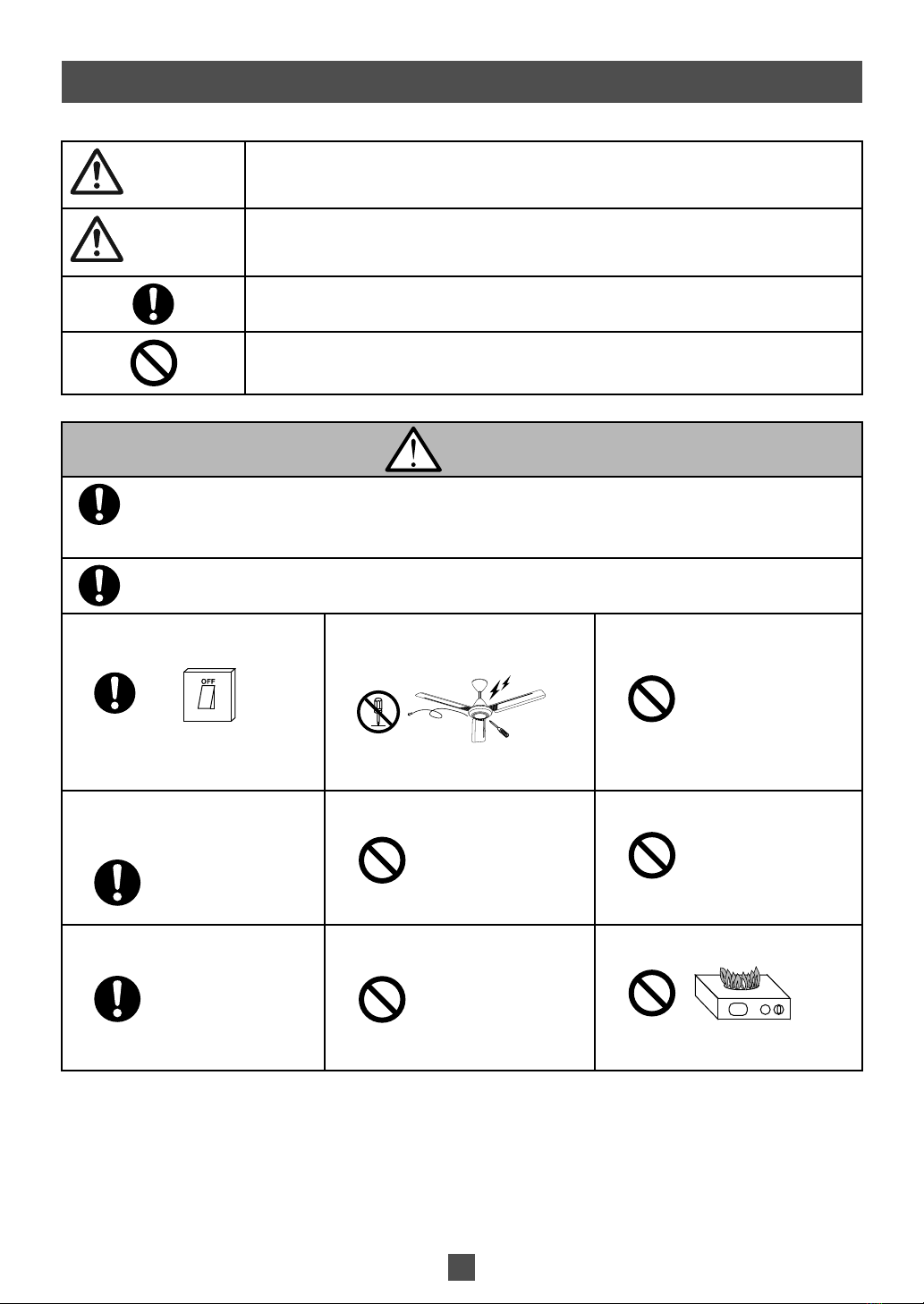
KDK M56RG User manual

Contents Page
Safety Precautions 2
Supplied Parts 4
How To Assemble 4
How To Use 12
Maintenance 12
Product Specification 12
Thank you for purchasing KDK Ceiling Fan.
Ceiling Fan
Model Number
M56RG
N56RG
Operating And Installation Instructions
Before operating this product, please read the instructions carefully, and keep this manual
for future reference.

2
Safety Precautions
To avoid the possibility of causing injury to users or damage to properties, please follow all the explanations written below.
WARNING A state that may be caused by the mishandling of products, which, if not avoided, may lead to the
possibility of death or serious injury of users.
CAUTION
A state that may be caused by the mishandling of products, which, if not avoided, may result in the injury
of users or property damage.
This symbol denotes an action that is COMPULSORY.
This symbol denotes an action that is PROHIBITED.
WARNING
Follow strictly to all the instructions given in this manual for installation.
Electrical wiring must be done by competent personnel.
Installation must be done by a qualified personnel.
Installation error can cause fire, electrical shock, Ceiling Fan drops and injuries.
Stop using the Ceiling Fan when any abnormality or failure occurs and turn “OFF” the Miniature Circuit Breaker (MCB).
(Risk of smoke, fire, electric shock and drop)
Switch off power supply and wait until
the Blade is fully static, before cleaning
or doing any maintenance jobs.
Can cause Ceiling Fan to move
suddenly, injuries and electrical shock.
Kindly refer to your sales agent for
repairing or maintenance issue.
Do not dismantle the Ceiling Fan unless
stated by this manual.
Must use only supplied parts.
Can cause fire, electrical shock, Ceiling
Fan drops and injuries.
Avoid damage wire during installation
eg. Deform due to heat, twist, bend, etc.
Can cause fire, explosion, short circuit
and electrical shock.
Ensure the Pipe has been fully tighten
to Motor Shaft. (Bolt tightening torque
is 800~1200 N•cm) and Cotter Pin
must fix into Bolt and bent.
Can cause injury if Ceiling Fan drops.
Ensure Ceiling Hook can afford more
than 10 times the Ceiling Fan weight.
Can cause injury if Ceiling Fan drops.
Do not sprinkle water to Ceiling Fan. Or,
do not wet Ceiling Fan.
Can cause fire, explosion, short circuit
and electrical shock.
Tighten the Blade Screws firmly using
a screwdriver.
Can cause injury if Blade drops.
Do not use power supply other than
rated voltage mentioned.
Overheating can cause electrical shock
and fire.
Do not install near a flammable area
such as a gas cooker.
Can cause fire, explosion, short circuit
and electrical shock.

3
WARNING
Do not touch the Ceiling Fan while it is
operating.
Can cause injury, damage and Ceiling
Fan drops.
Do not hang up to the Ceiling Fan.
Can cause Ceiling Fan drops and
injuries.
Dismantle the broken or damage
Ceiling Fan.
Can cause Ceiling Fan drops and
injuries.
Avoid installing Ceiling Fan at oily and
dusty places.
Can cause fire, explosion, short circuit
and electrical shock.
Do not install near chemicals and alkali.
Can cause fire, explosion, short circuit
and electrical shock.
CAUTION
This appliance is not intended for use by persons (including children) with reduced physical, sensory or mental
capabilities, or lack of experience and knowledge, unless they have been given supervision or instruction
concerning use of the appliance by a person responsible for their safety. Children should be supervised to
ensure that they do not play with the appliance.
To avoid the possibility of causing injury to users or damage to properties, please follow all the explanation
written in this manual. The manufacturer will not be responsible for any accidents and injuries caused by
defective, deficient installation or installation which does not follow to instruction manual.
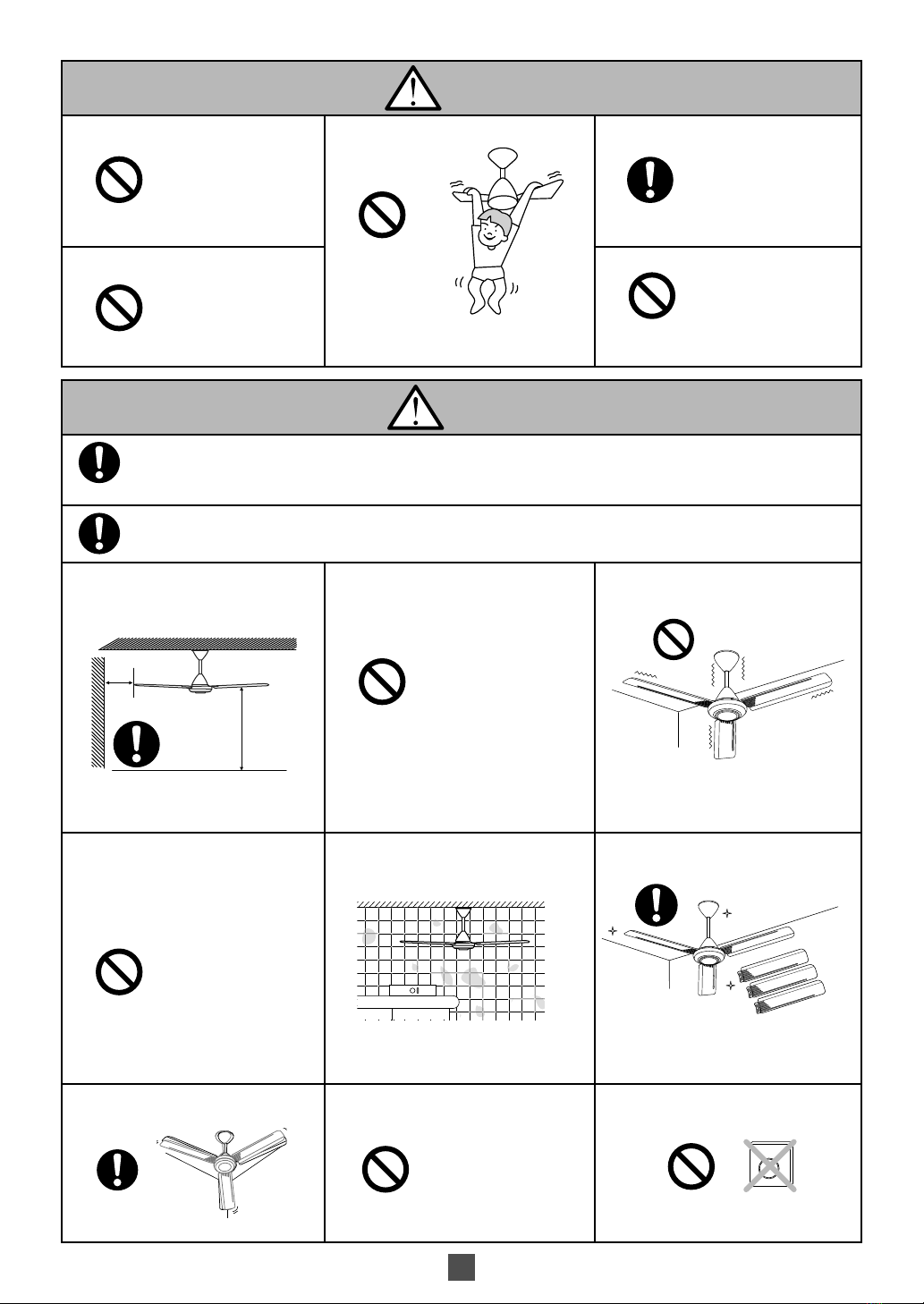
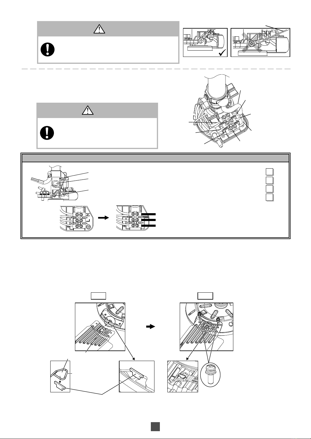
Ceiling Fan must be mounted above
2.5m from the floor and 1m from the
wall to the Blade. Avoid fixing inside the
dome ceiling.
More than 1m
More than 2.5m
Can cause injury if hit by the Blades.
Can cause unstable air flow and effect
the Ceiling Fan to wobble.
Avoid continuous exposure of direct
wind from the Ceiling Fan.
It may cause discomfort.
This product is for in house use only.
Can cause rusty, discolour, damage and
injury.
Do not install at places where there is high
vibration and impact.
Can cause injury if Ceiling Fan drops.
Do not use solvents (Gasoline and
petroleum) or any other chemicals.
Wipe away dirt with a clean soft cloth,
ordinary soap and water to keep the
fan clean.
Can cause plastic part deformation
and metal corrosion.
Do not install Ceiling Fan at a wet, high
temperature and high humidity area
such as shower room.
If an electrical current leakage occurs,
it can easily cause electrical shock and
fire.
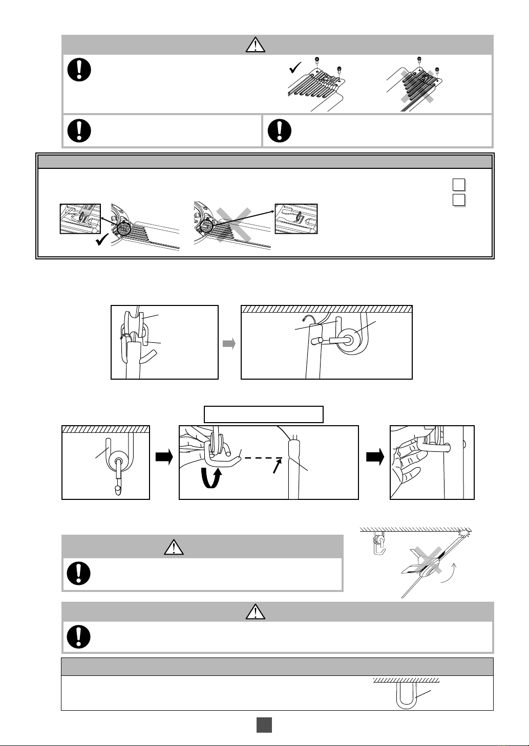
Replace all the Blades if any of them
broken or crack.
Vibration can cause the Ceiling Fan to
fall.
After installation make sure the Ceiling
Fan does not wobble extremely.
Can cause injury if Ceiling Fan drops.
This product is for in house use only. Do
not install at a windy places.
Can cause rusty, discolour, damage and
injury.
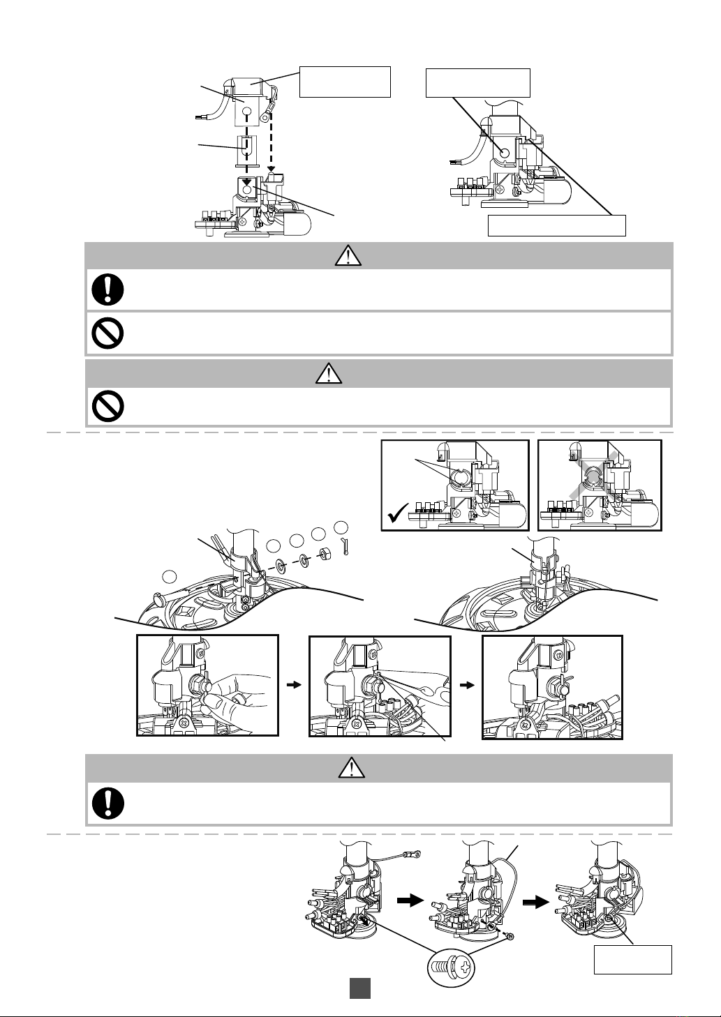
Do not connect the Ceiling Fan to
dimmer switch.
It can damage the Ceiling Fan.
Dimmer Switch

4
1
5
3
2
5
3
4
4
2
2
2
1
2
2
6
6
2
2
2
2
4
4
3
3
1
1
6
6
5
5
Spring Washer
Cotter Pin
Hexa Nut
P-R Washer
Ellipse Bolt
Pulley Set
Cap
M56RG N56RG
Parts Pcs
1. Motor Assembly 1
2. Blade Assembly Set 3
3. Pipe (9 or 12 or 16 or 18 or 22 inch) 1
4. Lower Canopy 1
5. Upper Canopy 1
6. Speed Regulator 1
7. Part Set 1
NOTE
The installation method for both models is the same.
Pipe
Pull Safety Wire
Safety Wire Screw (with washer)
NOTE
Do not place the Ceiling Fan directly on the floor.
Can cause scratches to the product.
Supplied Parts
How To Assemble
A) Insert the Canopy
1
1Pull out the Safety Wire from Pipe as shown. Remove Safety Wire Screw from Pipe. Keep these screws for Page 9
Step D2.

5
(
i) (ii)
Do not screw Lower and
Upper Canopy Screws
Pipe
Upper Canopy
(with logo brand)
Pipe
Power Cord (from power supply)
Ceiling
Upper Canopy
Lower Canopy
Lower Canopy
Check Point After Installation
1. Insert the Lower and Upper Canopy to Pipe and the screw is not tightened.
2. Upper Canopy (with logo brand) is on top of Lower Canopy (no logo brand).
Check
B) Assemble Pipe To Motor Assembly
1
1Pull the power cord (from power supply) and insert into the Pipe hole as shown.
2
2Insert Lower Canopy to the Pipe. Then insert Upper Canopy (with logo brand) to the Pipe.

6
a
bcde
Slit
Safety Switch Lever
Pipe
Motor Shaft Switch is pushed by Switch Lever.
Pipe hole and Motor
Shaft hole are aligned.
Cap
Safety Switch Lever
Cotter Pin is bent
NOTE: Do not remove
this Switch Lever.
Tighten the Safety
Wire Screw
Safety Wire
Safety Wire Screw
(with washer)
WARNING
Ensure Pipe has been fully tightened to Motor Shaft. (Bolt tightening torque is 800~1200N•cm).
And, Cotter Pin must be fixed into Bolt hole and bent.
Can cause injury if Ceiling Fan drops.
CAUTION
Do not remove the Switch Lever at Pipe.
Insert Pipe correctly to Motor Shaft.
Can cause product not operate if Switch has not been pressed down.
Do not press Switch with other object, except using the Switch Lever given.
Can cause fire, explosion, short circuit and electrical shock.
2
2First, insert the Cap to the Motor Shaft. Then, fix the Pipe to Motor Shaft as shown.
Ensure the Switch Lever press the Switch.
3
3Fix the Pipe and Motor Assembly with
a) Ellipse Bolt, b) P-R Washer, c) Spring Washer,
d) Hexa Nut and e) Cotter Pin. (All taken from Part Set)
The Slit position of the Bolt should be top and bottom.
Bend the Cotter Pin at last as shown.
4Remove Safety Wire Screw at shaft.
Fix the Safety Wire firmly to the shaft with
Safety Wire Screw.
WARNING
Do not bypass and short circuit the Safety Switch.
Can cause fire, electrical shock, Ceiling Fan drops and injuries.

7
Neutral (Blue)
Live (Brown)
Earth (Green/Yellow)
Check Point After Installation
1. Switch Lever press the Switch.
2. The Ellipse Bolt, P-R Washer, Spring Washer and Hexa Nut are firmly tightened
and the Cotter Pin is inserted and bent for safety reason.
3. Safety Wire Screw is firmly tightened.
4. All wires are connected correctly by competent personnel.
Check
Power cord
3 Pin Terminal
Live (Brown)
Live (Brown)
Earth (Green)
Neutral (Blue)
Earth (Green)
Black
Safety Wire
Wrong position
WARNING
Safety Wire must be fixed correctly and connected at
all time.
Can cause injury if Ceiling Fan drops.
Ensure the Safety Wire does not touch the Motor surface.
WARNING
Make sure all the Terminals are connected
correctly by competent personnel to avoid
electrical hazards.
Can cause fire, electrical shock, Ceiling Fan
drops and injuries.
C) Assemble Blade Assembly Set To Motor Assembly
1
1Remove Blade Screw (6 pieces, silver colour) from Motor Assembly.
Step 1 : Assemble Blade towards to the Cover Hook as shown in figure step 1.
Step 2 : Tighten the Blades firmly with Screws (Silver colour).Each Blade use 2 pieces of Screws.
(Tightening torque for reference : 250-300 N•cm)
5
5Connect the Power Cord to the 3 Pin Terminal.
Blade Screw (6 pieces)
Blade hole
Blade Safety Hanger
Cover Hook
Step 1 Step 2

8
ATTENTION
In case “U” hook is being used, installation method is the same. “U” hook
Check Point After Installation
1. The Blade Screws (6 pieces) for securing the Blade Assembly are tightly screwed.
2. Blade Safety Hanger must fix at the position on Blade.
Check
CAUTION
Blade must be fixed correctly.
Can cause no air flow.
Can cause injury if blades drop.
Tighten the Blade Screws firmly using a
screwdriver.
Can cause injury if Blade drops.
Do not remove Blade Safety Hanger from Blade.
Can cause injury if Blade drops.
Ceiling Hook
(“J” Hook)
Pulley
C Hook
Pulley
1st step
Take out Pulley Set from Parts Set,
after that cross it to Pipe.
2nd step
Place Pulley onto Ceiling Hook.
ALTERNATIVE METHOD
1st step
Place the Pulley Set to the Ceiling Hook
as shown in the picture.
2nd step
Incline Pulley Set and install Ceiling Fan.
Make sure the Fan maintain straight to avoid the Blade from
touching the ceiling during installation.
Ceiling Hook
(“J” Hook)
Alligned Parallel
Pipe Hole
C Hook
WARNING
Ensure Ceiling Hook can afford more than 10 times the Ceiling
Fan weight.
Can cause injury if Blades drops.
CAUTION
Ensure Ceiling Fan is not tilted so that the Blade does not touch the ceiling during installation.
Can cause unstable air flow and effect the Ceiling Fan to wobble.
D) Installation to Ceiling
1
1Install to Ceiling.

9
E
L
L
NN
CAUTION
Safety Wire must fix correctly.
Can cause injury if Ceiling Fan
drops.
Safety Wire Screw
(with washer)
Red
Live
Black
Green/Yellow
Black
White
Ceiling Fan
Terminal
Terminal
Live in
Earth
Neutral
Motor
Regulator
Live in
WIRING DIAGRAM
Brown
Connector Capacitor
Source
Connector
Brown
Earth
Rated voltage is
mentioned on product.
Regulator
Ceiling Fan
Wall switch
(On / Off)
Check Point After Installation
1. The Ceiling Fan is securely fixed onto the Ceiling Hook.
2. The Safety Wire is loopped to the Ceiling Hook and securely screwed to
the Pipe.
Check
Ceiling Hook
Safety Wire Screw
Safety Wire
Pipe
WARNING
Electrical wiring must be done by competent personnel.
Can cause fire, electrical shock, Ceiling Fan drops and injuries.
CAUTION
This product is not provided with cord and plug or with other means for connection from the supply. When connect
or change the power cord or lead wire, it must be performed by qualified personnel in order to avoid a hazard.
Please use 227IEC53(RVV) or thickness of tube is 1mm or above. (Other requirements such as diameter of lead
wire, please use according to the regulation of the country). This product should be installed with a double poles
single throw switch (Breaker Switch) with minimum 3mm contact gap in the fixed installation circuit.
E) Wiring Instruction
1
1Connect power supply according to the Wiring Instruction below.
2Loop the Safety Wire to the Ceiling Hook and screw it to the Pipe using Safety Wire Screw. Use the screw which was
removed from Page 4, Step A1.
CONNECTING THE POWER SUPPLY

10
(80.6)
(62~64)
(7~8)
(4~5)
(4~5)
(80.6)
(57)
(9~10)
L1 L2
L1
CAUTION
Should there be a dimmer switch, disconnect it and reconnect the wiring as shown.
Ceiling
Approximately 5mm
Upper Canopy
Connect
Directly
Power Supply
Dimmer Switch
200V Class Regulator
Check Point After Installation
1. The Upper Canopy is securely fixed.
2. The Lower Canopy is securely fixed.
Check
Check Point After Installation
1. The wiring is connected properly to the power supply.
Check
F) Fix the Canopy
1
1Adjust Upper Canopy position and fix Upper Canopy
to Pipe firmly by screwing them as shown.
The distance of Upper Canopy and Ceiling is
approximately 5mm.
2
2Pull down Lower Canopy untill it stop and fix to Pipe firmly by screwing them as shown.
G) Installation of Speed Regulator
1
1The dimension for the Speed Regulator is shown in the Diagram.

11
L1
L 1
L1
L 1
Speed Regulator Base
Terminal 1
Screw
Regulator Cover
Switch
Wood Screw
Holes
Wall Plug
Live Wire
Live Wire
Holes
Screw
Protruding parts
ATTENTION
Wood Screw and Wall Plug is not supplied.
2Loosen the screw from the Speed Regulator Cover. Open the Speed Regulator by lifting up the Speed Regulator
Cover from the base.
3Insert the live wire from the wall through the hole of the Speed Regulator Base as shown.
4Fix the Speed Regulator box to the wall by screwing the screws as shown.
5Connect the Live Wire with the Terminal as shown.
6To close the Speed Regulator, insert the two holes on top of the
Speed Regulator to the two protruding parts at the base.
Finally, screw them together.
Live Wire (from power supply)
Live Wire (to motor assembly)

L
Switch Knob
Pitching Method
Hold the Motor Assembly by hand and adjust the Blade carefully untill the height (L) differences is ±1 mm.
Push up or press
down carefully
Hold by hand
CAUTION
After installation make sure the Ceiling Fan does not wobble
extremely.
Can cause injury if Ceiling Fan drops.
H) Final Confirmation
1
1Measure the distance using a measuring tape.
Please adjust all the Blades to get the equal distance from ceiling to the Blade Tip, L (within 1 mm tolerance).
How To Use
1
1To turn on the fan, simply turn the Switch Knob to any position (1, 2, 3, 4, or 5). To turn off
the fan, turn the Switch Knob to the (0) position.
Maintenance
1. Check the Ceiling Fan condition annually. If a problem occurs, stop using the Ceiling Fan. Then refer to service, sales or
maintenance shop.
Check points : Loosened Screws, Safety Wire condition, Motor Shaft damage, etc.
2. Keep the Ceiling Fan clean. Wipe away dirt with a clean soft cloth, ordinary soap and water. Wipe it again to dry it. Do not
use solvents (Gasoline or petroleum).
* Please do not bend the Blade while cleaning.
3. Do not paint the Blades. If damage, order new set of Blades (3 pieces) from service shop or sales shop.
4. When referring to service, sales or maintenance shop, show this instruction to them and maintain correctly.
5. If the product is broken or damage, please remove the Ceiling Fan from ceiling and replace with a new Ceiling Fan. This is to avoid the
Ceiling Fan drops.
6. Recommendation for the Ceiling Fan suspension system shall be examined at least once every two years.
Product Specification
Model Type
Voltage Frequency Wattage (W) Rotation (RPM)
Air Velocity (m/min) Air Delivery
(m³/min)
VAC Hz Low High Low High
M56RG/
N56RG TB 220 50 14 70 103 268 165 220
230 15 75 109 275 170 225
R
M56RG8001CM
KDK Company, Division of PES
Head Office: 4017, Takaki-cho, Kasugai, Aichi, Japan.
© KDK Company, Division of PES 2011
This manual suits for next models
1
Table of contents
Other KDK Fan manuals
Popular Fan manuals by other brands

Home Decorators Collection
Home Decorators Collection YG683AP-PL Use and care guide

YitaHome
YitaHome JMOMQ-V1 Assembly instructions

BVN
BVN BSV-D 650 User manual & certificate of warranty

Vortice
Vortice CA-IL Instruction booklet

kincrome
kincrome KP1013 manual

Suntec Wellness
Suntec Wellness CoolBreeze 4000 SV manual