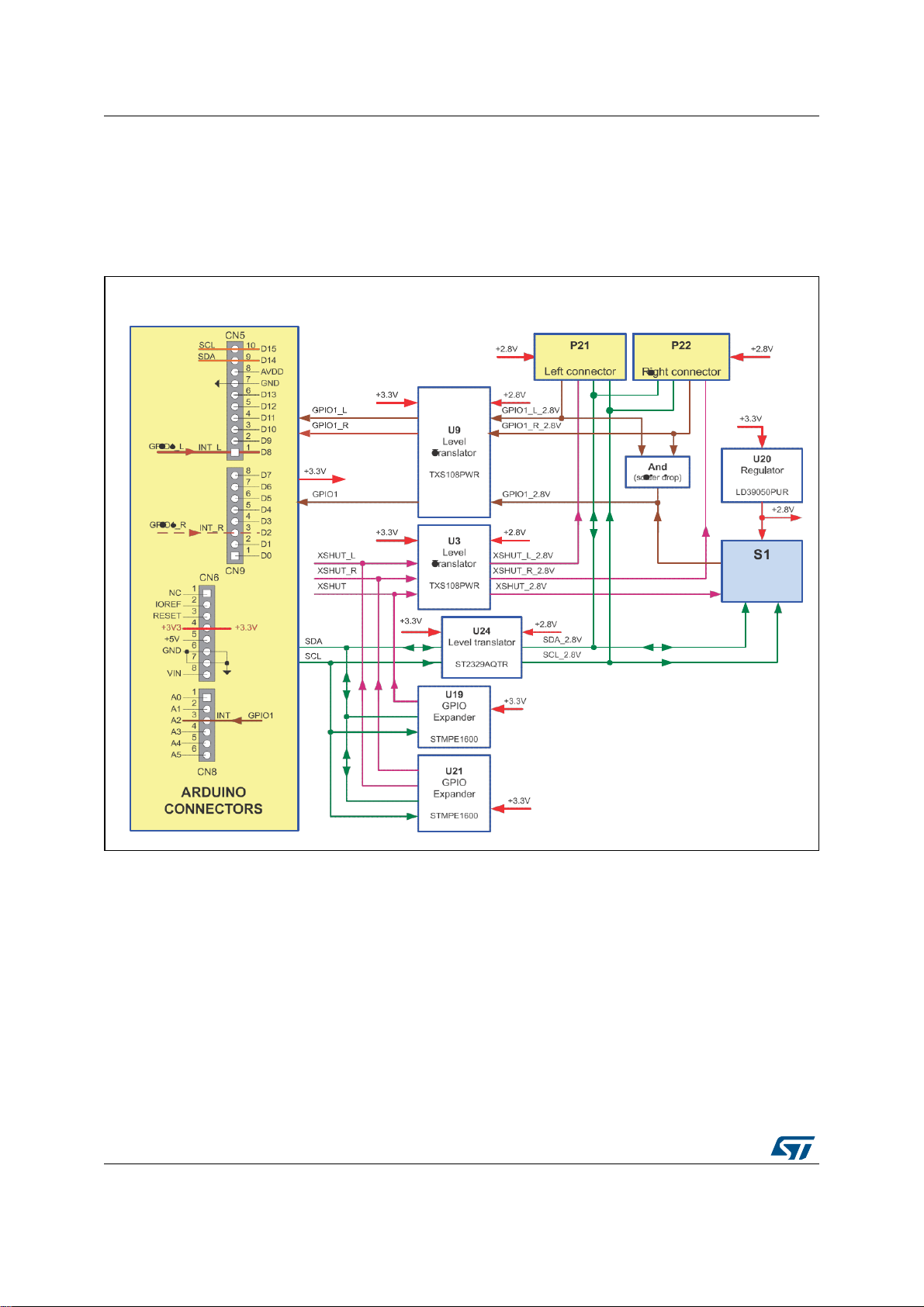
3.3 Solder drop configurations
Solder drops allow the following configurations of the X-NUCLEO-53L3A2expansion board:
•
If the developer wants to make an application with several expansion boards stacked
and there is:
–conflict with the microcontroller port allocation, the GPIO1 can be output on the
CN8/A4 (U17 fitted) of the Arduino connector. The default configuration is that
GPIO1 is output on the CN8/A2 (U14 fitted) of the Arduino connector.
–conflict on the I2C addresses, the addresses of the STMPE1600 can be modified
(the default addresses A2, A1, A0, 000, and 001).
•
If the developer wants to connect breakout boards (see Figure 5) to the X-NUCLEO-
53L3A2 expansion board:
–the VL53L3CX interrupt of the left breakout board can be output on the CN5/D9
(U10 fitted) or CN5/D8 (U11 fitted) of the Arduino connector. By default, the U10
and U11 are not fitted.
–the VL53L3CX interrupt of the right breakout board can be output on the CN9/D4
(U15 fitted) or CN9/D2 (U18 fitted) of the Arduino connector. By default, the U15
and U18 are not fitted.
–the VL53L3CX interrupts of the left and right breakout boards, GPIO1_L and
GPIO1_R, can be shared with the VL53L3CX interrupt on the main board,
GPIO1, by fitting U7 and U8 solder drops. By default U7 and U8 are not fitted.
10/17