BBQ Guru CyberQII User manual

BB Q G URU C Y B E R Q II USE R G UID E Rev.1.07 for
V1.09 - V1.12 & V1.1A - V1.2A Firmware

Page 2
1. SAFETY WARNINGS........................................................................................................................................................................ 3!
2. LIMITED WARRANTY..................................................................................................................................................................... 4!
3. DESCRIPTION ................................................................................................................................................................................... 4!
4. BBQ GURU CYBERQII Features....................................................................................................................................................... 4!
5. PROBES.............................................................................................................................................................................................. 5!
6. CONTROLLER CONNECTIONS...................................................................................................................................................... 5!
7. KEYS .................................................................................................................................................................................................. 5!
8. POWERING UP.................................................................................................................................................................................. 6!
8.1. Startup Screen............................................................................................................................................................................. 6!
9. STANDARD DISPLAY SCREENS ................................................................................................................................................... 6!
9.1. Main Display Screen................................................................................................................................................................... 6!
9.2. Pit 1 Setpoint Display Screen ..................................................................................................................................................... 6!
9.3. Pit 1 Ramp Display Screen ......................................................................................................................................................... 7!
9.4. Pit 2 Setpoint Display Screen ..................................................................................................................................................... 7!
9.5. Pit 2 Ramp Display Screen ......................................................................................................................................................... 7!
10. BATTERY, BACKLIGHT, BEEPER AND DISPLAY SETUP ....................................................................................................... 7!
10.1. Battery Power Display Screen .................................................................................................................................................. 7!
10.2. Backlight Intensity Set Screen .................................................................................................................................................. 8!
10.3. Backlight Time Set Screen........................................................................................................................................................ 8!
10.4. Contrast Set Screen................................................................................................................................................................... 8!
10.5. Alarm and Key Beeps Set Screen ............................................................................................................................................. 8!
11. PIT 1 USER SETUP SCREENS........................................................................................................................................................ 8!
11.1. Fan 1 Percentage Display Screen.............................................................................................................................................. 9!
11.2. Pit 1 Set Screen......................................................................................................................................................................... 9!
11.3. Pit 1 Hold Set Screen................................................................................................................................................................ 9!
11.4. Food 1 Set Screen ..................................................................................................................................................................... 9!
11.5. Timer 1 Set Screen.................................................................................................................................................................... 9!
11.6. Timeout Action 1 Set Screen .................................................................................................................................................. 10!
11.7. Alarms 1 Set Screen................................................................................................................................................................ 10!
11.8. Ramp 1 Set Screen.................................................................................................................................................................. 10!
11.8.1. Ramp Feature Description ............................................................................................................................................. 10!
11.9. Open Lid Detect 1 Set Screen................................................................................................................................................. 11!
11.9.1. Open Lid Detect Description ......................................................................................................................................... 11!
11.9.2. Open Lid Detect –Overshoot Eliminator....................................................................................................................... 12!
12. PIT 2 USER SETUP SCREENS...................................................................................................................................................... 12!
13. SUPER USER MENU..................................................................................................................................................................... 12!
13.1. Proportional Band Screen ....................................................................................................................................................... 13!
13.2. Ramp Offset Screen................................................................................................................................................................ 13!
13.3. Cycle Time Screen.................................................................................................................................................................. 13!
13.4. Deviation Alarm Screen.......................................................................................................................................................... 13!
13.4.1. Alarm Deviation Setpoint .............................................................................................................................................. 14!
13.5. Temperature Units Screen....................................................................................................................................................... 14!
13.6. Reset All Screen ..................................................................................................................................................................... 14!
14. STATUS SCREENS........................................................................................................................................................................ 15!
14.1. Food Done Alarm ................................................................................................................................................................... 15!
14.2. Pit Temp High Alarm ............................................................................................................................................................. 15!
14.3. Pit Temp Low Alarm.............................................................................................................................................................. 15!
14.4. Timeout No Action................................................................................................................................................................. 15!
14.5. Timeout Alarm ....................................................................................................................................................................... 16!
14.6. Timeout Shutdown.................................................................................................................................................................. 16!
14.7. Timeout Hold.......................................................................................................................................................................... 16!
14.8. Temperature Error Messages .................................................................................................................................................. 16!
14.9. Zero Adjust Screen ................................................................................................................................................................. 17!
14.10. Span Adjust Screen............................................................................................................................................................... 17!
14.11. Calibrating The Zero (Low end temperature)........................................................................................................................ 17!
14.12. Calibrating The Span (High end temperature) ...................................................................................................................... 18!
15. FIRMWARE UPDATES................................................................................................................................................................. 18!
16. ADAPTIVE CONTROL STRATEGY............................................................................................................................................ 18!
17. BUILDING A PROPER FIRE FOR GOOD CONTROL ................................................................................................................ 18!
17.1. Eliminating Large Fluctuations in the Pit Temperature........................................................................................................... 19!
17.2. To Extinguish The Pit............................................................................................................................................................. 19!
18. DEFINITION OF TERMS .............................................................................................................................................................. 19!
19. FLOW DIAGRAM OF STANDARD DISPLAY SCREENS.......................................................................................................... 20!
20. FLOW DIAGRAM OF USER SETUP SCREENS.......................................................................................................................... 21!
21. FLOW DIAGRAM OF SUPER USER MENU............................................................................................................................... 22!

Page 3
Important Note:ThisUser Guide refers to the operation of the CyberQII control unit
only (hardware). For information of the CyberQII Control Interface PC application,
please refer to its User Guide.
1.SA F E T Y W A RN IN GS
INST A L L A T IO N /SA F E T Y IN F O R M A T I O N:
R E A D A ND U ND E RST A N D T H IS USE R G U ID E C O M PL E T E L Y B E F O R E INST A L L I N G O R
USI N G T H IS PR O D U C T!!
W A R NI N G: FIRE HAZARD, BURN HAZARD!! Even quality electronics can fail CAUSING
THE BLOWER TO RUN CONSTANTLY AND CAUSING EXCESSIVE TEMPERATURES! Power
Draft Fans can get the temperature of your pit higher than through natural draft, so use extra caution in
opening your pit and determining its placement. Always inspect your probe wires for damage. Damaged
probe wires can cause the blower to run constantly causing your pit to become excessively hot.
W A R NI N G: FIRE HAZARD, BURN HAZARD!! FLAMES, SPARKS AND LIT
EMBERS CAN EXIT ANY OPENING ON YOUR PIT CAUSING FIRES - Keep your pit located a safe
distance from anything flammable like buildings, walls, solvents, cars, fuel, wood piles, furniture, etc. and
always use caution when opening the pit. Be aware that an ember that has fallen or is ejected from the
charcoal cooker can be blown by a light wind into a garage or other structure, debris field, woods, or grass
field and cause a fire to start. Always have a fire extinguisher and water supply close by. If the cooker is
to be used on a wooden or combustible surface such as a wooden deck, always place the cooker on a non-
flammable pad intended for this purpose.
W A R NI N G: FIRE HAZARD, BURN HAZARD !! Even quality electronics can fail and cause the
temperature to read incorrectly - BE SURE TO USE A REDUNDANT DIAL THERMOMETER AS A
BACKUP TEMPERATURE SENSOR ON YOUR PIT –This&will&allow&you&to&verify&your&control’s&
temperature reading for your safety.
W A R NI N G: SMOKE CAN COMBUST WHEN OXYGEN IS INTRODUCED AND PRODUCE
SEVER BURNS –ALWAYS USE CAUTION WHEN OPENING THE LID OR DOOR OF YOUR PIT.
W A R NI N G: KEEP YOUR CONTROL DRY –Allowing your control to get wet can cause
damage to its electronics and/or make it operate incorrectly CREATING A HAZARDOUS CONDITION.
W A R NI N G: Pit fires can occur when liquids are spilled or when cooking at temperatures that
cause surfaces inside the cooker to reach the ignition temperature of fats. Never pour or toss water directly
into a fat fire. Reduce the temperature by cooling the fire in the firebox with a water spray. Close the
cooking chamber door and the firebox while it is steaming to smother the fire. This procedure may need to
be repeated several times before the pit fire is under control.
N O T E : Pit fires can be largely avoided if the cooker is kept clean and free from fat
buildup during or between cooks. Changing drip trays during a cook cycle will help keep
flammable fats in the cooker to a minimum. Cooking temperatures should be kept low
enough to avoid ignition. You are dealing with an open fire when you are cooking on
charcoal and wood.

Page 4
W A R NI N G: There are hot surfaces on all parts of the cooker before during and after cooking.
Always wear protective clothing when tending the cooker or attempting to extinguish a fire or dumping a
firebox in the proper ash receptacle at the end of a cook. Always be ready to call your local Fire Company
in the case of an emergency before the
situation gets out of control.
C A U T I O N: fire danger is always present, even in the best of conditions. There is no substitute for
continuous safety scrutiny on the part of the user.
W A R NI N G: SHOCK HAZARD, HIGH VOLTAGE!! The power supply for this product is
plugged into a 120 or 240 VAC Mains. THIS VOLTAGE CAN KILL OR HURT YOU. KEEP THE
POWER SUPPLY AWAY FROM WATER AND OFF OF THE GROUND - do not let it get exposed to
rain or snow and NEVER TOUCH THE POWER SUPPLY IF IT GETS WET.
2.L I M I T E D W A RR A N T Y
THE BBQ GURU warrants this product to be free from defect in workmanship and materials for a period
of ninety days from the date of purchase.
1. Should unit malfunction, return it to the factory. If defective it will be repaired or replaced at no
charge.
2. There are no user serviceable parts on this unit. This warranty is void if the unit shows evidence
of being tampered with or subjected to excessive heat, moisture, corrosion or other misuse.
3. Components which wear or damage with misuse are excluded, e.g. relays, probes, etc.
4. THE BBQ GURU shall not be responsible for any damage or losses however caused, which may
be&experienced&as&a&result&of&the&installation&or&use&of&this&product.&&THE&BBQ&GURU‘s&liability&
for any breach of this agreement shall not exceed the purchase price paid E. & O.E.
3.D ESC RIPT I O N
The CYBERQII is the most advanced BBQ control on the planet. It is called the
CYBERQII because it can be accessed through cyber space from a remote location via its
USB interface and its Control Interface PC application. This awesome control is actually
two controls –it can be used to control two pits. Just check out some of the features
listed below.
4.BB Q G UR U C Y B E R Q I I Features
Super compact control allows you to control up to two pits simultaneously
Four thermocouple probes allow you to monitor two pits and two food items
USB interface allows monitoring and control from your PC or over the Internet
Digital alphanumeric 8 character x 2 line LCD display with user-selectable
backlight time
Audible alarm sounds on over/under temp, food done, timeout and other user-
settable conditions
Real-time fan status and percent output indication helps you to measure fuel use
Open Lid Detect
Adaptive Control Algorithm
Super User menu for advanced users
User-settable&“low&and&slow”&ramp&down&feature

Page 5
User-settable cook timer gives alarm, shuts down your pit, or will hold the pit at
the temperature you specify
Battery power indicator
Adjustable proportional band, cycle time, and deviation alarms (Super User
menu)
Display temperature in degrees C or F
Alarms settable to on or off (good neighbor feature)
Adjustable display contrast
32 to 475 deg F range with +/- 2 deg F accuracy
5.PR O B ES
The probes provided with your CyberQ are rugged stainless steel precision
thermocouples. These are not low cost thermistors like inexpensive monitors. The
thermocouple wires have an armor braid with moisture and smoke resistant teflon
insulation that is rated for temperatures up to 500 degrees F. The user can pass these thin
wires under the lid of the grill or through a small hole opening without creating a large
gap which would allow air to get through (air intrusion). Be careful not to kink these
rugged yet small wires or let them come in contact with flames. Always store them by
rolling them neatly and tying with the supplied Curleez. These probes are user-
replaceable and are available at
www.thebbqguru.com;
we recommend having a spare set
for unforeseen emergencies.
Important Note: Be sure to fully insert your probes into the control. Push the plug
into the connection securely until you feel and hear it snap in place. If you do not plug
the probes in securely, you may experience sporadic temperature readings and the
CyberQ will not control your cooker accurately. The temperature may also read low
causing you cooker to get excessively hot.
6.C O N T R O L L E R C O NN E C T I O NS
From left to right:
USB, Pit 1, Food 1, Pit 2, Food 2, Fan Output 1, Fan Output 2, 12V Power Input
7.K E YS
UP - Indexes the shown value up. Also returns you to the previous display menu.
D O W N - Indexes the shown value down. Also indexes you through the display
menu.
O N/O F F
- Powers the unit up and down. Must be held down for 2 seconds to
power on/off.
SC R O L L - Indexes you through all setup menus.

Page 6
UP + D O W N - Returns you to the main display screen from
any
screen.
UP + SC R O L L - Takes you to the main Super User menu.
D O W N + SC R O L L - Returns you to the main display screen from the
Super User menu.
8.PO W E RI N G UP
Pressing the ON / OFF
key will power up the control.
On power up the unit shows the Startup screen:
8.1.Startup Screen
The display will show the startup screen for approximately 2 seconds and then will show
the Main Display Screen:
C
Y
B
E
R
Q
2
1 .
0
5
1
0
0
In the above example, the version number is 1.05 and the serial number is 100.
9.ST A N D A RD DISP L A Y SC R E E NS
There are five different ways to display the temperatures, setpoints and status as
described below. Navigate through them using the down key. See the FLOW
DIAGRAM OF STANDARD DISPLAY SCREENS at the end of this document.
9.1.Main Display Screen
P1
2
5
0
F1
1
8
1
P2
2
2
5
F2
1
6
9
In this example, the top row shows the actual temperature (250) of pit 1 (P1) and the
actual temperature (181) of the food (F1) within pit 1.
The bottom row shows the actual temperature (225) of pit 2 (P2) and the actual
temperature (169) of the food (F2) within pit 2.
Dashes (---) will be displayed if no probe is plugged into the associated connector.
9.2.Pit 1 Setpoint Display Screen
P1
2
5
1
*
2
5
0
F1
1
7
9
S
P
1
8
0
This display screen shows the actual and set temperatures for pit 1 (P1) and its food (F1).

Page 7
On the top row: the leftmost digits are the actual pit temperature (P1). Dashes (---) will
be displayed if no probe is plugged into the associated connector. An * will be displayed
if the fan is running. The rightmost digits are the setpoint of pit 1.
On the bottom row: the leftmost digits are the actual food temperature (F1). Dashes (---)
will&be&displayed&if&no&probe&is&plugged&into&the&associated&connector.&&“SP”&indicates&
setpoint. The rightmost digits are the setpoint of the Food 1.
9.3.Pit 1 Ramp Display Screen
P1
2
5
1
F1
1
7
9
0
0
:
0
0
R
0
This display screen shows the actual temperatures of pit 1 (P1) and its food (F1). Dashes
(---) will be displayed if no probe is plugged into the associated connector.
The bottom row displays the&cook&timer.&&“R”&indicates&ramp&mode&is&turned&on&and&
currently&active.&“r”&indicates&ramp&mode&is&turned&on&but¬&active.&&The&percentage&of&
the fan running time is displayed as values 0 –9,&and&“F”&for&full&or&100%.&&An&*&will&be&
displayed if the fan is running.
9.4.Pit 2 Setpoint Display Screen
P2
2
2
6
*
2
2
5
F2
1
6
9
S
P
1
7
0
This display screen is identical to the screen described in section Pit 1 Setpoint Display
Screen, but for pit 2 (P2).
9.5.Pit 2 Ramp Display Screen
P2
2
5
1
F2
1
6
9
0
0
:
0
0
R
0
This display screen is identical to the screen described in section Pit 1 Ramp Display
Screen, but for pit 2 (P2).
10.B A T T E RY,B A C K L I G H T,B E E PE R A ND DISPL A Y SE T UP
The following screens are accessible by pressing the scroll key from the Main
Display Screen. Use the scroll key to move through the screens. Use the &
keys to set the values. Moving to another screen saves your chosen value. (See the
FLOW DIAGRAM OF USER SETUP SCREENS at the end of this document).
10.1.Battery Power Display Screen
B
A
T
T
P
W
R
Page 8
8
5
%
This screen displays the battery level (or the wall adaptor) in %, where 85% ~ 12VDC
and 100% ~ 14VDC. The Batter Power is useful mainly when powering from external
batteries or an automotive power source.
10.2.Backlight Intensity Set Screen
B
A
C
K
L
I
T
E
5
0
%
This screen allows you to set the backlight intensity from 0-100%. Use the &
keys to set to the desired intensity. Default value is 50%.
10.3.Backlight Time Set Screen
B
A
C
K
L
I
T
E
5
S
E
C
This screen allows you to set the backlight timer. Set from: OFF, 1, 5, 10 (seconds), ON.
Use the & keys to set the desired time (ON = energized constantly). Default
value is 5.
10.4.Contrast Set Screen
C
O
N
T
R
A
S
T
6
0
%
This screen allows you to set the contrast by using the & keys. Default value
is 60%.
10.5.Alarm and Key Beeps Set Screen
A
L
A
R
M,
K
E
Y
B
E
E
P
S
3
This screen allows you to set the alarm from 5 beeps to 0. If set to 0, the unit will not
beep when a key is pressed, nor will it beep for an alarm. If set from 1 to 5, it will beep
once when a key is pressed, and the number it is set to for an alarm. Use the &
keys to set the desired number of beeps. This feature is useful to help distinguish
your&control’s&alarms&from&other&nearby&controls.&&Default&value is 3.
11.PI T 1 USE R SE T UP SC R E E NS
The following screens are accessible by pressing the scroll key from the Pit 1
Setpoint Display Screen, as well as from the Pit 1 Ramp Display Screen. Use the scroll

Page 9
key to move through the screens. Use the & keys to set the values.
Moving to another screen saves your chosen value. (See the FLOW DIAGRAM OF
USER SETUP SCREENS at the end of this document).
11.1.Fan 1 Percentage Display Screen
F
A
N1
P
C
T
5
0
%
This screen displays the fan output percentage from 0-100%. This screen is useful to
determine the fuel level. If the fan is running 80% - 90% or more during the middle or
end of a cook, it may be time to add more charcoal.
11.2.Pit 1 Set Screen
P
I
T1
S
E
T
2
5
0
The temperature can be set from 32 to 475 degrees F using the & keys.
Default value is 275.
11.3.Pit 1 Hold Set Screen
P
I
T1
H
O
L
D
2
0
0
Pit 1 Hold is the temperature at which Pit 1 will be held if the Timeout Action is set to
Hold. Temperatures range from 32 to 475 degrees F. Default value is 200.
11.4.Food 1 Set Screen
F
O
O
D1
S
E
T
1
8
5
The temperature can be set from 32 to 210 degrees F using the & keys.
Default value is 185.
11.5.Timer 1 Set Screen
T
I
M
E
R1
0
0
:
0
0
The maximum value is 99:59, use the & keys to change the value. Default
value is 00:00.
Page 10
11.6.Timeout Action 1 Set Screen
T
I
M
E
0
U
T1
N
O
A
C
T"’
N
Options for the Timeout function are:
NO#ACT’N: do nothing when the set timer expires.
A L A R M: sound an alarm when the set timer expires.
SH U T D O W N: shut down the fan when the set timer expires.
H O L D:&&hold&pit&1’s&temperature&to&the&value&set&on&the&“Pit&1&Hold&Set&Screen”&
when the set timer expires.
The&default&setting&is&NO&ACT’N;&Use&the& & keys to change the value.
11.7.Alarms 1 Set Screen
A
L
A
R
M
S1
O
N
Values are OFF and ON. The temperature values for the alarms are setup in the Super
User Menu. The default setting is ON; Use the & keys to change the value.
11.8.Ramp 1 Set Screen
R
A
M
P1
O
F
F
Values are OFF and ON. The default setting is OFF; use the & keys to
change the value.
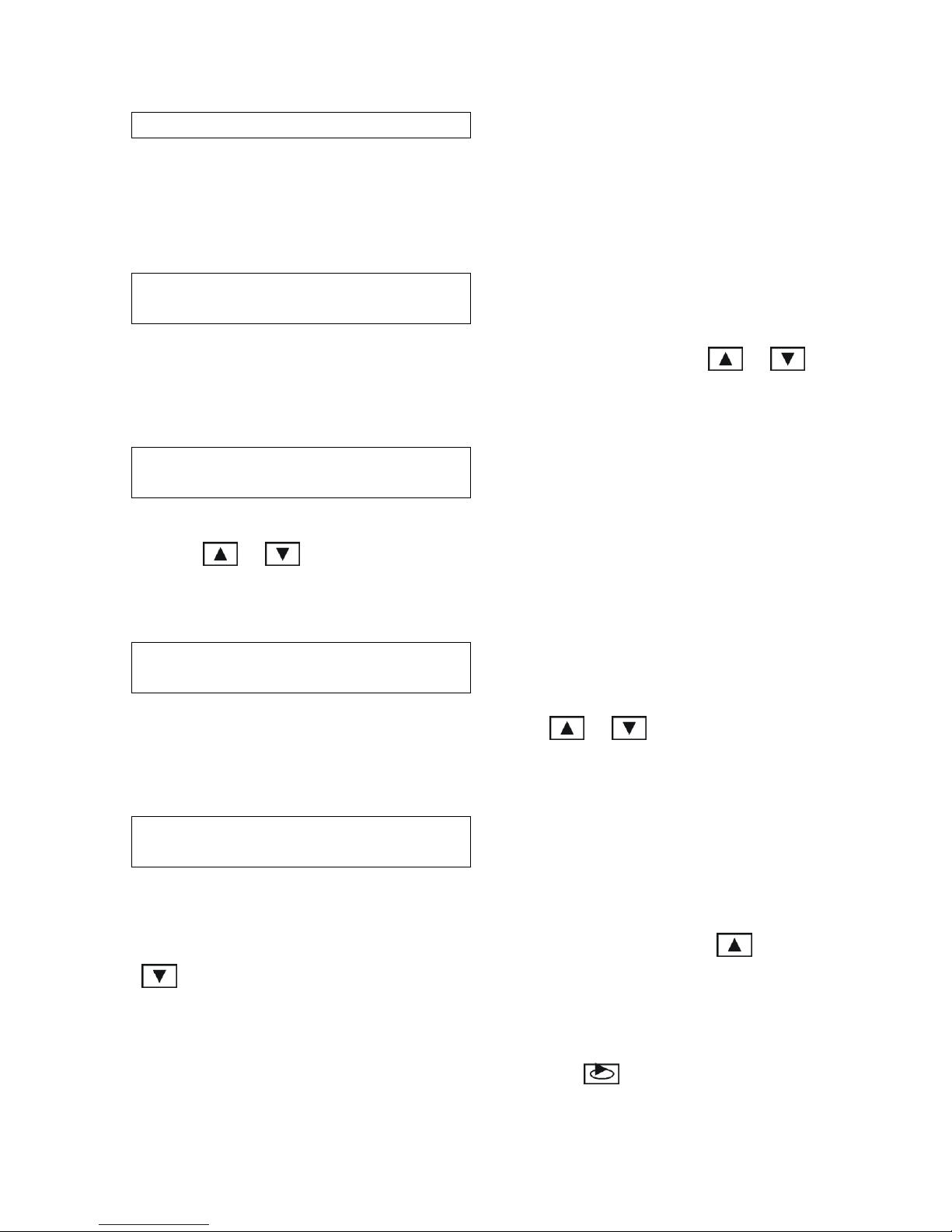
11.8.1. Ramp Feature Description
When the ramp is set to ON,&the&“low&and&slow”&ramp&mode&is&enabled.&&This&mode&is&
used for slow cooks so your food (meat) never over-cooks. Ramp mode is a very helpful
feature in preventing overcooking. The fan will control the pit temperature as follows:
the pit temperature will rise or remain steady as needed as the food temperature starts to
rise. But as the food temperature nears its set point, the fan will control the pit so that the
pit temperature will fall. Specifically this feature will gradually lower the pit temperature
toward the food set point temperature when the food is within 30° of being done. The
controller will hold the pit temperature slightly above your food set point as long as there
is fuel. This feature is similar to cook and hold, but the control calculates everything for
you.
The factory default setting is OFF so you must enable this feature to use it. Note when
using this feature, you may want to start your pit temperature a little higher than normal
to reduce cook time and not overcook your food. If the food probe is not plugged in and

Page 11
the ramp mode is turned on, the ramp led will show steady (ramp mode is turned on) but
no ramping will take place.
FOOD TEMPERATURE
PITTEMPERATURE
TEMPERATURE
TIME
11.8.1.1.Ramp = O N ResponsePlot
FOOD TEMPERATURE
PITTEMPERATURE
TEMPERATURE
TIME
11.8.1.2.Ramp = O F F ResponsePlot
11.9.Open Lid Detect 1 Set Screen
L
I
D1
O
P
E
N
O
F
F
Values are OFF and ON. The default setting is OFF; use the & keys to
change the value.
11.9.1. Open Lid Detect Description
This feature will allow quick recovery to the setpoint temperature after you open your lid.
When the Open Lid Detect is set to ON, the feature is&enabled.&&When&you&open&your&pit’s&
lid, the temperature will drop. This can cause the blower to over-fire the coals and cause
overshoot&when&the&lid&is&shut.&&This&mode&detects&when&the&pit’s&lid&is&open&and&
minimizes the blower running during that time. Some overshoot will always be present
when your pit’s&lid&is&opened&and&closed&even&if&the&blower&is&off,&because&it&still&
introduces oxygen to the fire. This prevents the low alarm erroneously sounding when
the temperature drops and the lid is open. The factory default is ON, so you must disable

Page 12
this feature if you have problems with excess air currents in your pit. To disable this
feature set it to OFF.
11.9.2. Open Lid Detect –Overshoot Eliminator
When the Open Lid Detect is enabled, the rate of temperature rise of your pit will be
limited preventing over-firing. This will make a typical startup to a temperature of 250
deg F take a minimum of about 20 minutes and will help to eliminate startup overshoot.
Take note in the chart below how the output is cycled on the approach to the setpoint of
300 deg. This minimizes the setpoint overshoot on startup.
12.PI T 2 USE R SE T UP SC R E E NS
Every screen described above under Pit 1 User Setup Screens sections is duplicated for
Pit 2.
The Pit 2 screens are accessible by pressing the scroll key from the Pit 2 Setpoint
Display Screen, as well as from the Pit 2 Ramp Display Screen. Use the scroll key to
move through the screens. Use the & keys to set the values. Moving to
another screen saves your chosen value. (See the FLOW DIAGRAM OF USER SETUP
SCREENS at the end of this document).
13.SUPE R USE R M E NU
Press the up and scroll & keys to enter the Super User Menu.
Press the up and down & or down and scroll & keys to exit the
Super User Menu and return to the Main Display Screen. (See the FLOW DIAGRAM
OF SUPER USER MENU at the end of this document).

Page 13
The screens are shown in the order they appear as the scroll key is pressed. When
the Reset All screen is reached and the scroll key is pressed again the menu system will
return to the Main Display Screen.
Use the & keys to set the values. Moving to another screen saves your chosen
value.
If the unit is left showing any screen for more than 10 seconds, it will revert to the Main
Display Screen.
13.1.Proportional Band Screen
P
R
O
P
B
A
N
D
2
5
D
E
G
The advanced user can adjust the Proportional Band from 1- 99 deg F. The default value
is 25 deg F. For clarification of this feature see the definition of terms section at the end
of this manual.
13.2.Ramp Offset Screen
R
M
P
O
F
F
S
T
3
0
D
E
G
The advanced user can adjust the Ramp Offset from 10-60 deg F. The default value is 30
deg F. This offset is used as follows: When the controller is in ramp mode the internal
pit setpoint will be ramped down from the pit setpoint to the Food Setpoint + Ramp
Offset. For clarification of this feature see the definition of terms section at the end of
this manual.
13.3.Cycle Time Screen
C
Y
C
T
I
M
E
6
S
E
C
The advanced user can adjust the cycle time from 4 to 10 seconds. The default value is 6
seconds. For clarification of this feature see the definition of terms section at the end of
this manual.
13.4.Deviation Alarm Screen
A
L
A
R
M
D
E
V
5
0
D
E
G
The advanced user can adjust the Deviation Alarm from 20 to 80 deg F. The default
value is 50 deg F (50° above or below set temperature). The low deviation alarm is

Page 14
suppressed on startup, and will sound when the pit temperature is above or below the pit
setpoint by this amount.
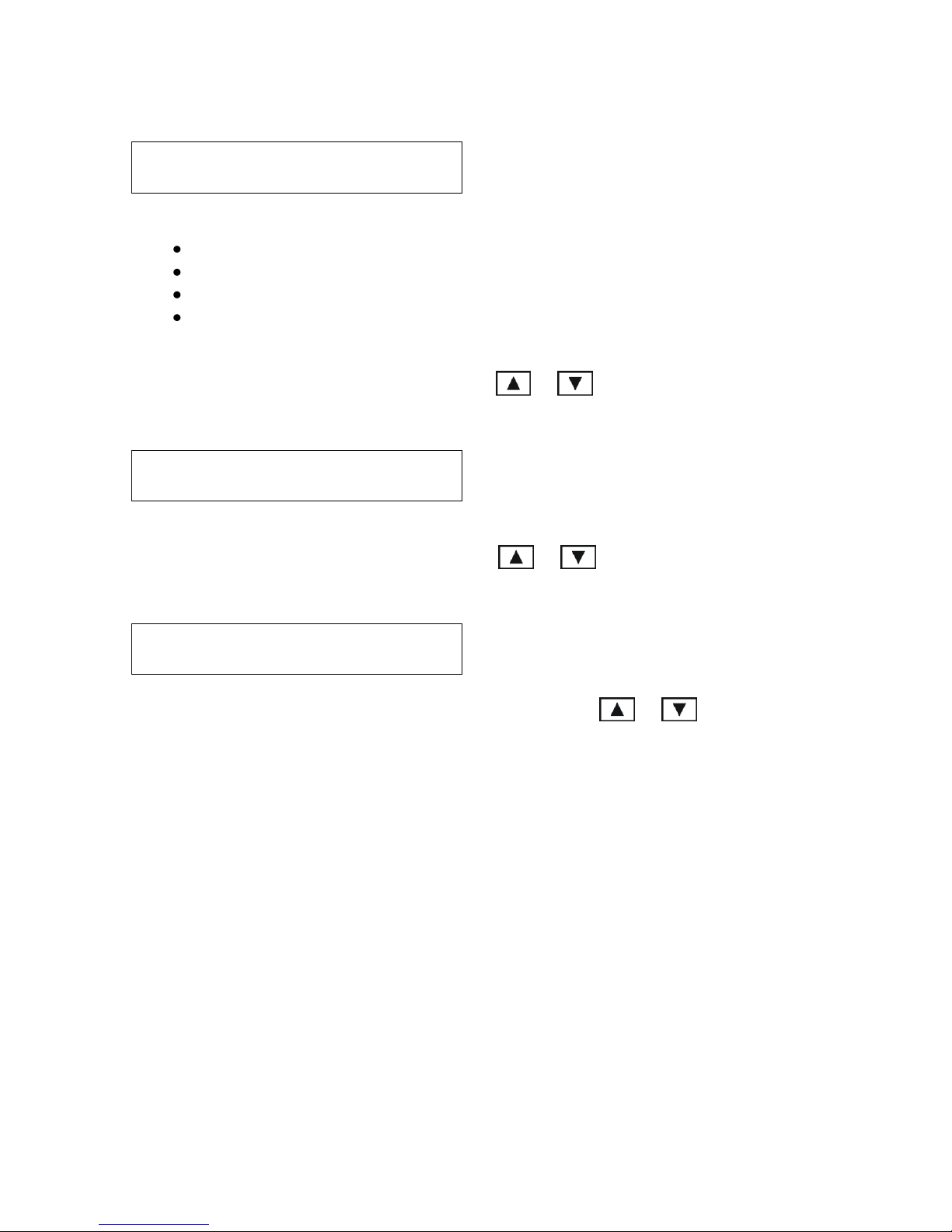
13.4.1. Alarm Deviation Setpoint
If the temperature of the pit deviates above the setpoint by the alarm deviation setpoint,
the&alarm&will&sound&and&the&display&will&blink&“Pit&Temp&High!”.
If the temperature of the pit deviates below the setpoint by the alarm deviation setpoint,
the&alarm&will&sound&and&the&display&will&blink&“Pit&Temp&Low!”.
The low alarm will not sound when your control is first powered up and your pit is cold.
The alarm is only allowed once the temperature gets close to the pit temperature setpoint.
The alarm deviation is settable from 20 to 80 degF and the factory default is 50 degF.
If the ramp feature is turned on and the pit is actively ramping, the only time that the low
alarm will become active is if the pit temperature drops 20 degrees F below the food
(meat) setpoint temperature to let you know that something is wrong, for instance you are
out of charcoal.
Pit
Setpoint
Deviation Alarm
Setpoint
Gives"“Hi”"Alarm
Gives"“Lo”"Alarm
Deviation Alarm
Setpoint
Pit Temperature
Time
13.4.1.1.Deviation Alarm ResponsePlot
13.5.Temperature Units Screen
T
E
M
P
U
N
I
T
F
D
E
G
The advanced user can set the temperature units to F or C. Default setting is F. This
affects all temperature displays and settings.
13.6.Reset All Screen
R
E
S
E
T
A
L
L

Page 15
The advanced user or technician can restore the factory defaults to all values programmed
in the unit, including calibration.
When the up key is pressed the display will show:
R
E
S
E
T
A
L
L
D
O
N
E
!
14.ST A T US SC R E E NS
14.1.Food Done Alarm
F
O
O
D1
D
O
N
E
!
The Food Done alarm screen flashes when the Food temperature is greater than or equal
to the Food setpoint. The beeper will sound if Alarms are set to ON. The Food 2 screen
would be identical to the above.
14.2.Pit Temp High Alarm
P
I
T1
T
E
M
P
H
I
G
H
!
The Pit Temp High alarm screen flashes when the pit temperature is greater than or equal
to the pit setpoint + the deviation alarm value
50 deg F default
(50° above set
temperature). The beeper will sound beeper if Alarms are set to ON. The Pit 2 screen
would be identical to the above.
14.3.Pit Temp Low Alarm
P
I
T1
T
E
M
P
L
O
W
!
The Pit Temp Low alarm screen flashes when the pit temperature is less than or equal to
the pit setpoint - the deviation alarm value
50 deg F default
(250° below set
temperature). The beeper will sound beeper if Alarms are set to ON. The Pit 2 screen
would be identical to the above.
14.4.Timeout No Action
T
I
M
E
O
U
T1

Page 16
The Timeout No Action alarm screen flashes when the timer is expired and Timeout
Action is set to No Action. The beeper is not sounded. The Timeout 2 screen would be
identical to the above.
14.5.Timeout Alarm
T
I
M
E
O
U
T1
A
L
A
R
M
The Timeout Alarm screen flashes when the timer is expired and Timeout Action is set to
Alarm. The beeper will sound beeper if Alarms are set to ON. The Timeout 2 screen
would be identical to the above.
14.6.Timeout Shutdown
T
I
M
E
O
U
T1
S
H
U
T
D
O
W
N
The Timeout Shutdown alarm screen flashes when the timer is expired and Timeout
Action is set to Shutdown. The beeper will sound beeper if Alarms are set to ON. The
Timeout 2 screen would be identical to the above. When this occurs, the corresponding
setpoint will be set to 0 and it is likely that the corresponding Pit High Temp alarm will
also display.
14.7.Timeout Hold
T
I
M
E
O
U
T1
H
O
L
D
The Timeout Hold alarm screen flashes when the timer is expired and Timeout Action is
set to Hold. The beeper will sound beeper if Alarms are set to ON. The Timeout 2
screen would be identical to the above. When this occurs, the corresponding setpoint will
be set to the Hold setpoint and it is possible that the corresponding Pit High Temp alarm
will also display.
14.8.Temperature Error Messages
Temperature Error messages are shown when the temperature is either too high or the
probe is not plugged in. If the alarm key beeps are set to 0 no audible alarm will
accompany them, otherwise the alarm will sound even if the alarms are set to off for
Pit/Food 1 or 2. To clear this message and silence the alarm, press any key.
When the pit 1 temperature is over 475 deg F or the probe is unplugged the display will
show the following. Pit 2 Temp Error message would be identical.
P
I
T1
T
E
M
P
E
R
R
O
R

Page 17
When the food1 temperature is over 475 deg F or the probe is unplugged the display will
show the following. Food 2 Temp Error message would be identical.
F
O
O
D1
T
M
P
E
R
R
O
R
14.9.Zero Adjust Screen
Using the & keys a factory technician or skilled user can adjust the zero
calibration from -99 to +99. Zero calibration should be adjusted with an input of 32
degrees to the Food thermocouple input.
In the below example, the F1: 32 is the value the control thinks it is seeing on the Food 1
input. The +1 is the amount we are adding or subtracting from the reading to make it
read correctly.
Z
E
R
O
A
D
J
+
1
F1
:
3
2
14.10. Span Adjust Screen
Using the & keys a factory technician or skilled user can adjust the span
calibration from -99 to +99. Span calibration should be adjusted with an input of
approximately 212 degrees to the Food thermocouple input.
In the below example, the F1: 212 is the value the control thinks it is seeing on the Food
1 input. The -4 is the amount we are adding or subtracting from the reading to make it
read correctly.
S
P
A
N
A
D
J
-
4
F1
:
2
1
2
14.11. Calibrating The Zero (Low end temperature)
1. Press and hold & and apply electrical power, continue to hold them down
until the ZERO ADJ Screen is shown. Let the CyberQ warm up for about 15-20
minutes before proceeding.
2. The display will now show the adjustment amount and the temperature of the
food 1 probe.
3. In a Styrofoam cup make an ice / water slurry using about 75% ice and 25%
water. Fill it to the top with the slurry. Place the food probe into the bottom of
the cup and stir it using the probe. Give the probe a couple of minutes to settle in
the cup.
4. Adjust the value shown on the display to show 33 degrees F using the &
keys. Remember that the display only updates every 3 seconds.
5. Proceed to Calibrating the Span by pressing the key.

Page 18
14.12. Calibrating The Span (High end temperature)
1. The display will now show the adjustment amount and the temperature of the
food 1 probe.
2. Fill a second Styrofoam cup with some water that is at a rolling boil. Be careful
not to get burned. Place the food probe into the bottom of the cup and stir it
around gently. Give the probe a couple of minutes to settle in the cup.
3. Adjust the value shown on the display to show 211 degrees F using the &
keys. Remember that the display only updates every 3 seconds.
4. Return to the Zero calibration by pressing the key. And perform calibration
according to Calibrating the Zero step # 3.
5. To exit the calibration, either power down by pressing the
key.
15.F IR M W A R E UPD A T ES
Firmware updates can be downloaded to your control and are available from The BBQ
GURU. The CyberQII Control Interface PC application is required to perform the
firmware upgrade of your control. Reference the CyberQ2 PC Application User Guide’s&
“Update&Unit&Firmware“&Section&to&learn&how&to&perform&the&firmware&update.&&&Just&call&
or email the BBQ GURU with your request, have your serial number ready and they will
email you a firmware upgrade file.
16.A D APT I V E C O N T R O L ST R A T E G Y
The CyberQII Adaptive Control Strategy is designed to operate with a wide variety of
bbq pits by continually learning what your pit is doing and adapting to many factors such
as outside air temperature, amount of charcoal, damper settings, etc. For the CyberQII to
work properly and determine how to adapt, the temperature inside the pit cannot be
oscillating up and down and the lid must stay closed. If you open the lid often, especially
on startup, the control cannot be expected to maintain setpoint. If you leave the lid closed
for approx 10-20 minutes, the temperature will become stable after the control adapts. If
the lid has been shut for at least 20 -30 minutes and you notice the temperature going up
and down significantly (+/- 10 degrees or more) the fan damper needs to be closed more;
try ½the current setting. Sometimes the Pit may run a few degrees high or low due to
various&conditions;&don’t&sweat&it,&the&control&will&bring&it&back&to&setpoint.&&Also&
remember that pit temperatures of 20 degrees high or low rarely have an affect on the
quality of food.
17.BUI L DI N G A PR O PE R F IR E F O R G O O D C O N T R O L
How you build the fire in your pit is critical for good control, especially at low
temperatures.&&Stack&the&charcoal&inside&your&pit&so&it’s&shaped like a pyramid, small at
the top and large at the bottom. Light the fire by lighting a few coals at the top. Do not
over-fire the charcoal or light it at the bottom, because this will only translate into startup
overshoot and over-firing. Some overshoot is normal and it may take a while for the fire
to stabilize.

Page 19
17.1. Eliminating Large Fluctuations in the Pit Temperature
Normally the CyberQ will be able to adjust the airflow via the blower to deliver precise
control and no damper adjustment will be required. If the pit has become over fired or if
you built the fire too big, you may see large temperature swings (+/- 10 deg or more). To
eliminate this you may need to restrict the airflow by adjusting the blower damper. A
good rule of thumb is that if you see large temperature swings, try closing the damper to
half the current setting; the pit should stabilize within 10-15 minutes after adjustment.
17.2. To Extinguish The Pit
If there is fuel left over from the cook, you can save this fuel by closing off any open
dampers or removing the blower and plugging the inducer sleeve opening with a kill
plug. This should put the fire out in about 30-45 min.
18.D E F IN I T I O N O F T E R MS
Proportional Band –This value is the band of temperature over which the power draft
fan will pulse. Say your internal pit setpoint is 225 (215 + 10 deg offset). Below 200 the
power draft blower will be full on, above 225 the power draft blower will be full off and
at 212.5 the power draft blower will cycle 50% of the time. The default value of 25
degrees will work well with most pits. If you notice that the pit temperature is oscillating
up and down more than 5 to 10 degrees and never settles out, the proportional band can
be made larger. Making the proportional band smaller will make the pit reach the
setpoint faster, but will also increase the overshoot on startup. Each time you adjust the
proportional band, expect that you will also need to adjust the offset to make the pit
setpoint and actual temperature agree.
CycleT ime–This value is the time (in seconds) between power draft fan pulses. The
default value of 6 seconds will work well with most pits.
Ramp Offset –When the ramp mode is turned on, the pit will be ramped down to the
Food setpoint + the ramp offset when the Food temperature = the Food setpoint. The
default value of 30 degrees will work well for most cuts of meat. For instance if your pit
setpoint is 275 and your Food setpoint is 180, the pit will be ramped down to 210
(180+30) as your Food temperature climbs to 180. We determined the 30 degrees based
on the amount of evaporative heat loss in an average piece of meat. If you make this
lower the Food setpoint may never be achieved at the end of the ramp cycle due to the
amount of evaporative heat loss. If you make this higher the Food setpoint may be
slightly exceeded at the end of the ramp cycle.

Page 20
19.F L O W DI A G R A M O F ST A ND A R D DISPL A Y SC R E E NS
FOOD 1 PROBE TEMP
MAIN DISPLAY
SCREEN
PIT 1 PROBE TEMP
PIT 2 PROBE TEMP
P1275F1185
P2275F2185
FOOD 1 PROBE TEMP
P1270 * 275
F1140SP185
PIT 1 PROBE TEMP
PIT 1 SET
POINT
FAN IS RUNNING
FOOD 1 SET POINT
SET POINT
FOOD 1 PROBE TEMP
P1270F1275
00:00 R0
PIT 1 PROBE TEMP
COOK TIMER
r = ramp mode on
R = ramping active
% FAN (0 –9 and F for full)
FOOD 2 PROBE TEMP
FOOD 2 PROBE TEMP
P2270 * 275
F2140SP185
PIT 2 PROBE TEMP
PIT 2 SET
POINT
FAN IS RUNNING
FOOD 2 SET POINT
SET POINT
FOOD 2 PROBE TEMP
P2270F2275
00:00 R0
PIT 2 PROBE TEMP
COOK TIMER
r = ramp mode on
R = ramping active
% FAN (0 –9 and F for full)
PIT 1 SETPOINT
DISPLAY SCREEN
PIT 2 SETPOINT
DISPLAY SCREEN
PIT 1 RAMP
DISPLAY SCREEN
PIT 2 RAMP
DISPLAY SCREEN
Other manuals for CyberQII
1
Table of contents
Other BBQ Guru Control Unit manuals


Popular Control Unit manuals by other brands


Swegon
Swegon TBLZ-1-66 installation instructions

Fireye
Fireye MBCE-110FR manual

Sensocon
Sensocon A1 Series Installation and operation manual

Bardiani Valvole
Bardiani Valvole GIOTTO TOP Instruction, use and maintenance manual

LOVATO ELECTRIC
LOVATO ELECTRIC RGK700 installation manual

ITT Industries
ITT Industries Bell & Gossett B-38 instruction manual