Table of Contents
5
1. INTRODUCTION .............................................................................................................................................7
1.1. Who Should Use..................................................................................................................................7
1.2. Purpose and Scope...............................................................................................................................7
1.3. Manual Version and Change Record...................................................................................................7
Figure 1-1: M3628PUD.....................................................................................................................7
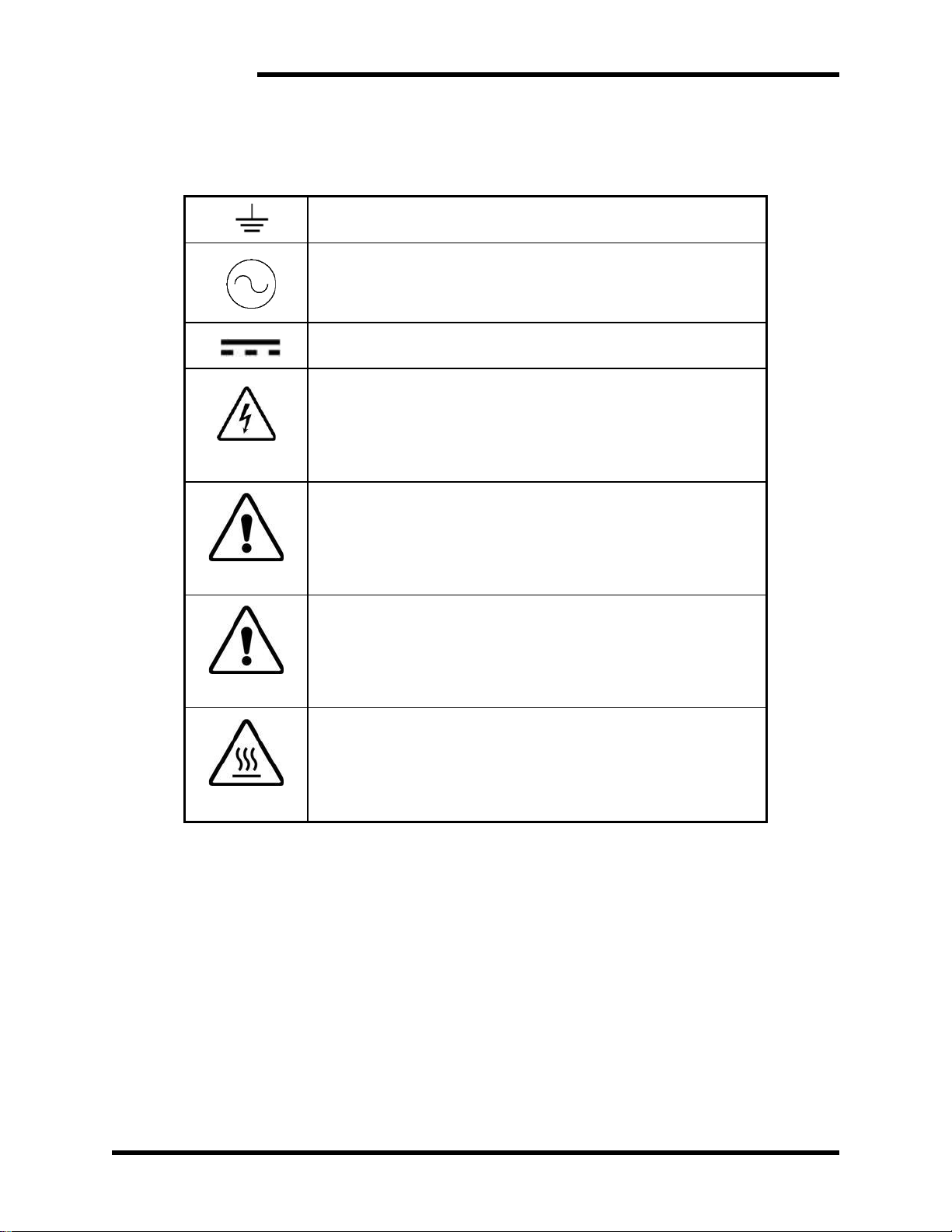
1.4. Symbol Conventions Used in this Manual and on Equipment ............................................................8
2. PRODUCT DESCRIPTION ...............................................................................................................................9
2.1. Related Products..................................................................................................................................9
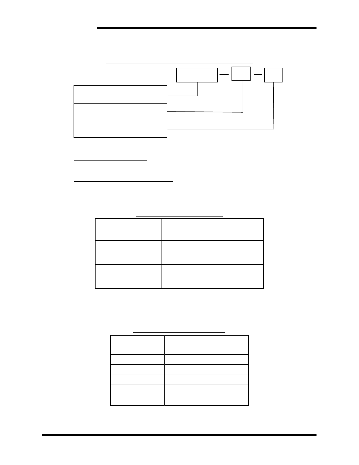
2.2. Part Number Breakdown ...................................................................................................................10
Figure 2-1: Example of Part Number Breakdown ...........................................................................10
Table 2-1: Capacitor Voltage...........................................................................................................10
Table 2-2: Capacitance Rating.........................................................................................................10
2.3. General Specifications.......................................................................................................................12
Table 2-3: General Specifications Table..........................................................................................12
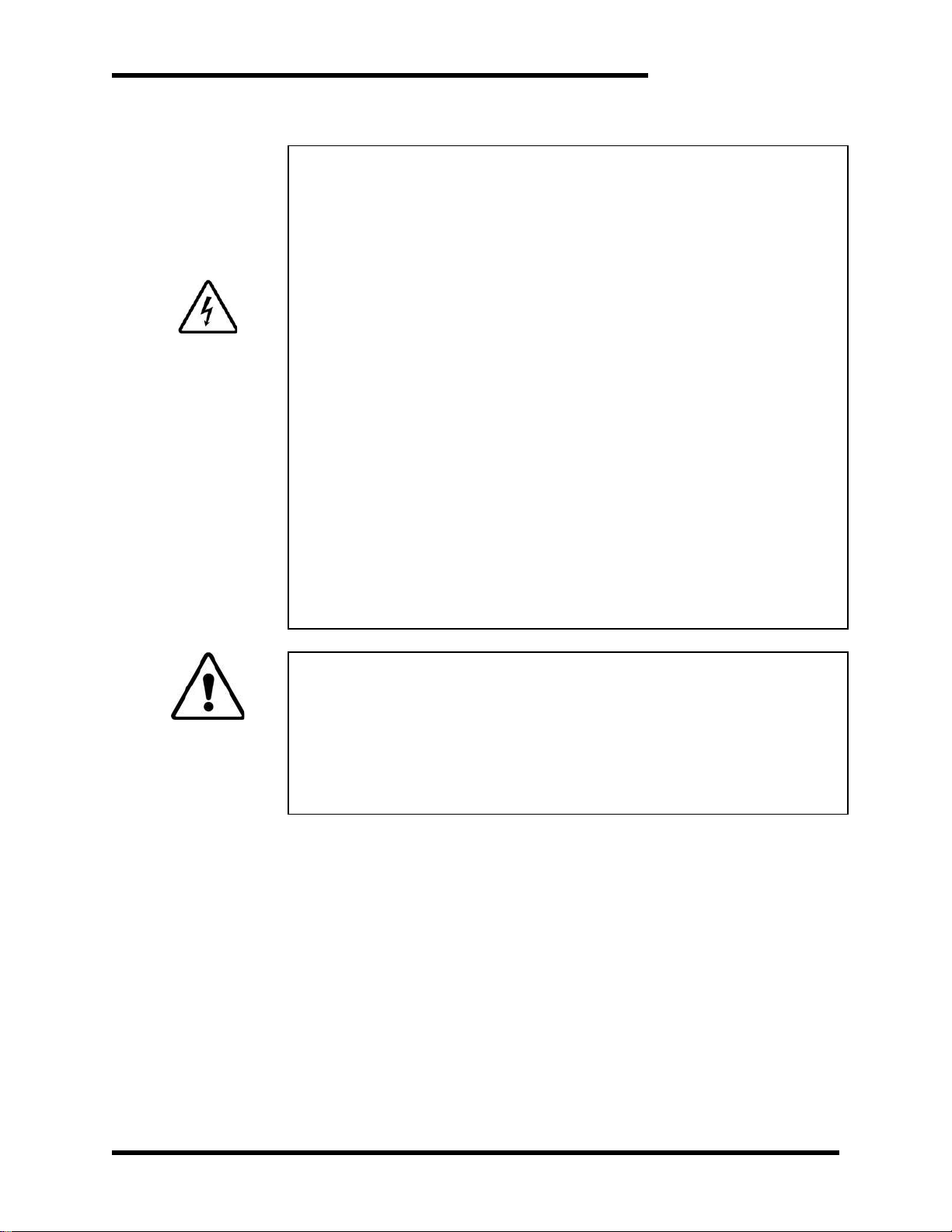
General Precautions and Safety Warnings...................................................................................................13
3. INSTALLATION INSTRUCTIONS...................................................................................................................14
3.1. Environment ......................................................................................................................................14
3.2. Wiring and Customer Connections....................................................................................................14
3.2.1. Power Wiring..............................................................................................................................14
Figure 3-1: M3628PUD...................................................................................................................14
3.2.1. Discharge Connections ...............................................................................................................14
3.2.2. Source Considerations ................................................................................................................15
4. OPERATION .................................................................................................................................................16
4.1. Functional Description.......................................................................................................................16
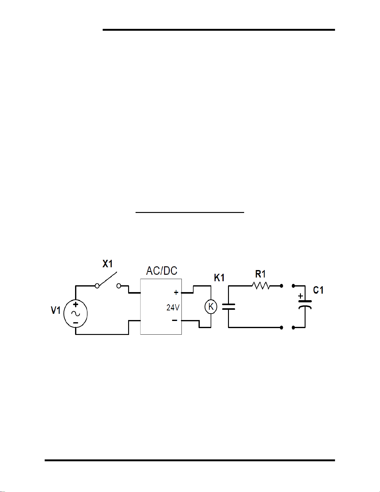
The M3628PUD module is powered by plugging in the 120V or the 240V line cord. The module uses a
switch to close a DC contactor across an internal resistor. When the switch is placed in the
“DISCHARGE ON” position, the voltage on the Ultra-capacitor module will decrease to a safe level
within 60 seconds. Once the digital display indicateS that the capacitor is drained, the discharge
switch can be placed in the “DISCHARGE OFF” position until the exhaust air from the discharger
is close to ambient room temperature................................................................................................16
4.2. Circuit Schematic...............................................................................................................................16
Figure 4-1: M3628UMT Schematic.................................................................................................16
4.3. Hardware Features.............................................................................................................................17
4.3.1. AC Power Input Connector.........................................................................................................17
4.3.2. Power Switch / Circuit Breaker ..................................................................................................17
4.3.3. Discharge switch.........................................................................................................................17
4.3.4. DC Capacitor Connectors ...........................................................................................................17
4.3.5. Display........................................................................................................................................17
4.3.6. Discharge Resistor......................................................................................................................17
4.3.7. Cooling fan .................................................................................................................................17
5. STARTUP AND TROUBLESHOOTING............................................................................................................18
5.1.1. Pre-power checks........................................................................................................................18
5.1.2. Discharge Procedure...................................................................................................................18
5.2. Troubleshooting.................................................................................................................................19
Table 5-1: Discharge System Troubleshooting................................................................................19
6. ENGINEERING DATA ...................................................................................................................................20
6.1. Ratings Chart.....................................................................................................................................20
Table 6-1: Ratings Chart..................................................................................................................20
Table 6-2: Dimensions.....................................................................................................................20