manuals.online logo
Brands
  1. Home
  2. •
  3. Brands
  4. •
  5. Beam
  6. •
  7. Antenna
  8. •
  9. Beam ISD710 User manual

Beam ISD710 User manual

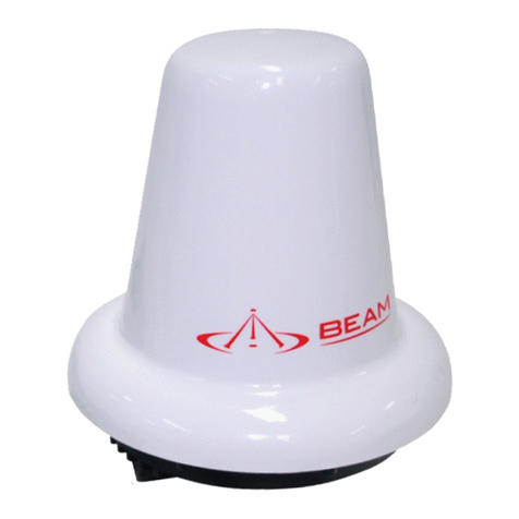
ISD710
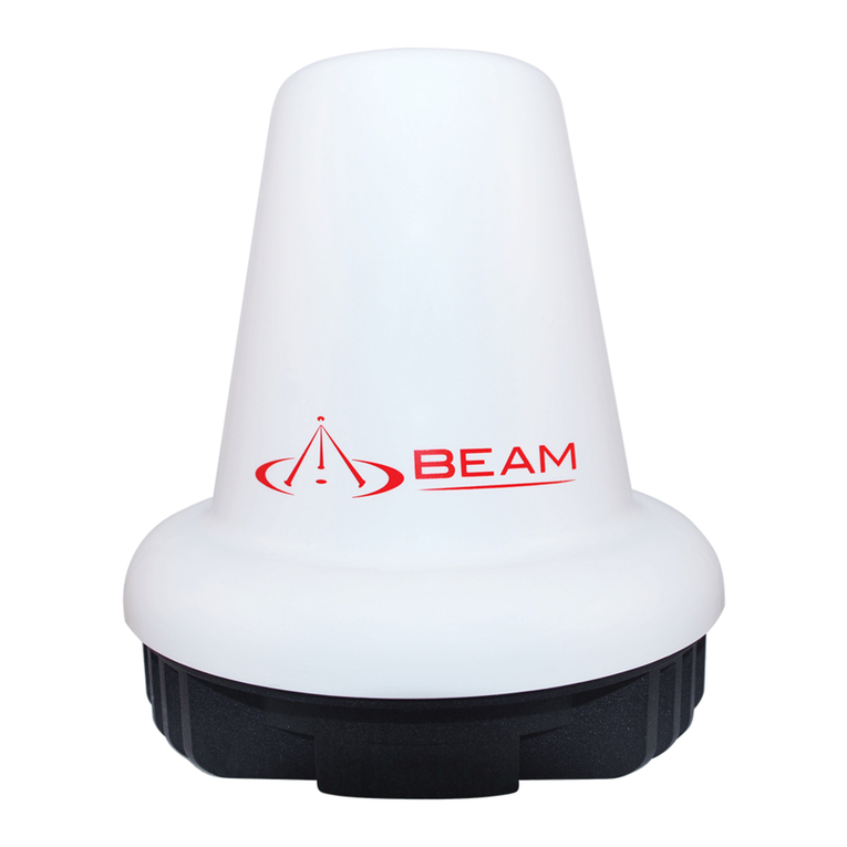
Maritime Antenna
(Active)
Installation Guide
Suitable for IsatDocks
www.beamcommunications.com
PART #: USRMAN006404
BEAM Communications
8 Anzed Court, Mulgrave
Victoria, 3170, AUSTRALIA
Web: www.beamcommunications.com
Info: [email protected]om
Support: suppor[email protected]
Tel: +61 3 8588 4500
Fax: +61 3 9560 9055
ANTENNA SPECIFICATIONS
AMPLIFIER + INTEGRAL ANTENNA
EQUIPMENT TYPE Mobile or Fixed Base Station
INTEGRATED OPERATING ENVIRON-
MENT
[ x ] Commercial
[ x ] Light Industry & Heavy Industry
POWER SUPPLY REQUIREMENT 32V DC maximum
RF INPUT POWER RATING (US &
CANADA)
30.0 dBm or 1.0 Watt peak (con-
ducted)
RF OUTPUT POWER RATING (US &
CANADA)
37.5 dBm or 5.6 Watts peak (con-
ducted)
DUTY CYCLE N/A
TX OPERATING FREQUENCY RANGE 1626.5 - 1660.5 MHz
RX OPERATING FREQUENCY RANGE 1565.19– 1585.65 MHz (GPS)
1518-1559 MHz (Inmarsat)
RF OUTPUT IMPEDANCE 50 Ohms
CHANNEL SPACING N/A
OCCUPIED BANDWIDTH
(99%)
83.1 KHz
MODULATION TX Modulation: GMSK
RX Modulation: OQPSK
EMISSION DESIGNATION* G7W
ANTENNA CONNECTOR
TYPE
Integral
ANTENNA DESCRIPTION Manufacturer: Aeroantenna Technology, Inc.
Type Marine
Model: AT1595-82
Frequency Range:
GPS 1565.19– 1585.65 MHz,
Inamarsat Receive: 1518-1559 MHz,
Inamarsat Transmit: 1626.5-1660.5 MHz
GPS Amplier Gain: 26 dB
INMARSAT RECEIVE Amplier: 26 dB
INMARSAT TRANSMIT Amplier: 11 dB
Antenna: 3.5 dBi (for model AT1595-82)
AMBIENT TEMPERATURE
RATING STORAGE:
OPERATIONAL:
-40°C to +80°C
-25°C to +55°C
WARNING
All antenna cables used must be compliant with approved dB signal loss. Failure to use Beam approved
antenna cables may result in non-compliance, degraded performance and may damage the IsatPhone Pro.
This device complies with Part 15 of the FCC Rules. Operation is
subject to the following two conditions: (1) this device may not
cause harmful interference and (2) this device must accept any
interference received, including interference that may cause
undesired operation.
To Satisfy FCC RF exposure requirements for mobile transmitting
devices, a separation distance of 55cm or more should be
maintained between the antenna of this device and persons during
device operation. To ensure compliance, operations at closer than
this distance is not recommended.
The antenna used for this transmitter must not be co-located in
conjunction with any other antenna or transmitter.
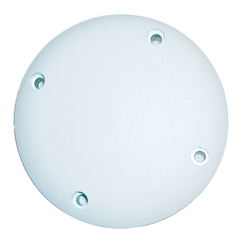
Maritime Antenna Kit Contents
1. Maritime Antenna
2. Pole or Mast Mounting Bracket
to suite 34mm diameter pole
3. 3 x Small Mast Mounting Grub Screws
4. 3 x Large Antenna Mounting Screws
5. 3 x Small Split Washers
6. 3 x Large Flat Washers
2
13
4
5
6
Step Three:
Attach both SMA connectors
to the bottom of the antenna
making sure to connect
the GPS cable to the GPS
connector and the Inmarsat
Cable to the ISAT connector.
Step Four:
Place the antenna on top of the
mast or pole and screw in the
3 mounting screws (with a split
washer and a at washer on
each) to hold it into place.
Step One:
Antenna Cables to be brought
to top of pole or mast
Step Two:
Place pole or mast mounting
bracket over the top of the
pole or mast and fix with 3
grub screws.
Antenna Coverage
Installation Guidelines
To ensure maximum performance of the antenna system and to
maximise availability and reliability of service the antenna must;
• have a clear line of site to the sky
• be clear and free of obstructions
• be clear of metal objects
• be located away from other transmitting devices
• be securely axed in location
• not be located indoors
• be installed in conjunction with a certied cable
Installing Antenna Cables
When installing antenna cables, follow these guidelines:
• Route and restrain cables to prevent them from vibrating
or moving under normal conditions, which could result in
damage to the antenna or the coaxial cable connections.
• Wherever the cables contact structures, protect the
cables from chang or abrasion. If a cable needs to be
bent, avoid kinking it, and ensure that each bend radius
follows the cable supplier limits.
• Use coaxial sealant, shrink‐wrap tubing, electrical tape,
or another suitable product to seal all cable connections
appropriately to prevent moisture and corrosion damage
from weather exposure.
• Mount all antennas vertically and clear of nearby metal
obstructions.
• Minimize horizontal obstructions as much as possible
because they can create areas of poor system coverage.
Installation Options
The antenna system is suitable for marine, vehicle and
xed applications and is designed to meet Inmarsat System
performance requirements when installed according to the
instructions in this guide.
The following gure shows typical Installations:
The antenna must be installed without obstruction of other
instruments or structures. The antenna must not be positioned
within range of radar equipment or other RF interference.
I-4 Americas I-4 EMEA I-4 Asia-Pacic
WARNING
To satisfy FCC RF exposure requirements for mobile transmitting devices, a separation distance of 55 cm or
more should be maintained between the antenna of this device and persons during device operation. To
ensure compliance, operations at closer than this distance is not recommended.
WARNING
Galvanic Corrosion Protection
This antenna has a base and pipe adapter is constructed out of aluminum. When the antenna is mounted to a steel mast or
metallic bracket, a galvanic reaction can occur resulting in aluminum corrosion. To minimize corrosion the following steps
can be taken:
• apply self-fusing silicone tape to all connectors
• use a UV-resistant, non metallic mast when possible
• apply silicone grease or joint compound do all metallic surfaces that make contact with the antenna or mounting
adapter
• if possible use an insulating plastic or rubber sleeve between a steel mast and the aluminum adapter.
Sourced from Inmarsat
NOTE:For Satellite & GPS connection instructions please consult your Beam Inmarsat Product manual.
WARNING: Do not place the antenna anywhere there is a source of heat or fumes such as the ship’s exhaust.
Connects to IsatDock Connects to IsatDock
Connects to IsatDock
Maritime Antenna Installation Guide

Other manuals for ISD710

1

Other Beam Antenna manuals

Beam ISD710 User manual

Beam

Beam ISD710 User manual

Beam ISD700 User manual

Beam

Beam ISD700 User manual

Beam RST700 User manual

Beam

Beam RST700 User manual

Beam RST705 User manual

Beam

Beam RST705 User manual

Beam RST210 User manual

Beam

Beam RST210 User manual

Beam RST703 User manual

Beam

Beam RST703 User manual

Beam RST710 User manual

Beam

Beam RST710 User manual

Beam MG200-VAB User manual

Beam

Beam MG200-VAB User manual

Beam Iridium User manual

Beam

Beam Iridium User manual

Beam RST706 User manual

Beam

Beam RST706 User manual

Beam RST740 User manual

Beam

Beam RST740 User manual

Beam RST202 User manual

Beam

Beam RST202 User manual

Beam Iridium RST740 User manual

Beam

Beam Iridium RST740 User manual

Beam RST715 User manual

Beam

Beam RST715 User manual

Beam RST720 User manual

Beam

Beam RST720 User manual

Beam RST701 User manual

Beam

Beam RST701 User manual

Beam RST220 User manual

Beam

Beam RST220 User manual

Beam RST714B User manual

Beam

Beam RST714B User manual

Beam RST710 User manual

Beam

Beam RST710 User manual

Beam RST710 User manual

Beam

Beam RST710 User manual

Beam RST720 User manual

Beam

Beam RST720 User manual

Beam RST715 User manual

Beam

Beam RST715 User manual

Beam Iridium RST706B User manual

Beam

Beam Iridium RST706B User manual

Beam RST215 User manual

Beam

Beam RST215 User manual

Popular Antenna manuals by other brands

Ramsey Electronics DAP25 Kit assembly and instruction manual

Ramsey Electronics

Ramsey Electronics DAP25 Kit assembly and instruction manual

Steren ANT-9029 instruction manual

Steren

Steren ANT-9029 instruction manual

Televes DAT 790 HD BOSS LR quick start guide

Televes

Televes DAT 790 HD BOSS LR quick start guide

Phonak TX-300V Optimization guide

Phonak

Phonak TX-300V Optimization guide

Diamond HF6FX instruction sheet

Diamond

Diamond HF6FX instruction sheet

Abel & Profit MFJ-17754 instruction manual

Abel & Profit

Abel & Profit MFJ-17754 instruction manual

Huawei Straight Talk H258C user guide

Huawei

Huawei Straight Talk H258C user guide

Hemisphere GPS A222 user guide

Hemisphere GPS

Hemisphere GPS A222 user guide

albentia ACC-A24R-S Quick installation guide

albentia

albentia ACC-A24R-S Quick installation guide

Gotting HG 71453-A manual

Gotting

Gotting HG 71453-A manual

RF Mogul RFM 960 Operation manual

RF Mogul

RF Mogul RFM 960 Operation manual

August DTA225 user manual

August

August DTA225 user manual

DX Engineering DXE-40VE-2 instructions

DX Engineering

DX Engineering DXE-40VE-2 instructions

TracStar MVS1200P2 F&D Assembly instructions

TracStar

TracStar MVS1200P2 F&D Assembly instructions

TERK Technologies TIAD6M QSG 03 quick start guide

TERK Technologies

TERK Technologies TIAD6M QSG 03 quick start guide

Revox AS-2000 manual

Revox

Revox AS-2000 manual

One Forall SV-9453 instruction manual

One Forall

One Forall SV-9453 instruction manual

1 BY ONE OUS00-0681 instruction manual

1 BY ONE

1 BY ONE OUS00-0681 instruction manual

manuals.online logo
manuals.online logoBrands
  • About & Mission
  • Contact us
  • Privacy Policy
  • Terms and Conditions

Copyright 2025 Manuals.Online. All Rights Reserved.