manuals.online logo
Brands
  1. Home
  2. •
  3. Brands
  4. •
  5. NK TECHNOLOGIES
  6. •
  7. Transducer
  8. •
  9. NK TECHNOLOGIES DTC 2-420-24U-FL User manual

NK TECHNOLOGIES DTC 2-420-24U-FL User manual

INSTRUCTIONS
1. Place wire to be monitored through aperture.
Ensuremonitoredcurrentflowmatchesarrowon
sensoror asnoted onfigure onreverse side.
2. Mount thesensor.
3. Connectoutputwiring.
A. Useup to 2.5 mm2(14 AWG)copperwires.
Tightenterminals to .6Nm (5 in-lbs)torque.
B. For current output models, ensure output
load is no more than 500 Ω.
C. For voltage output models, ensure output
load is at least 10KΩ.
4.Connect Power.
A. Connect the appropriate power supply.
5.Select Range.
A. ChosecorrectrangebypositioningtheRange
Jumper.
DTC 2 - 420 - 24U - FL
OUTPUT:
005- 0-5 VDC
010- 0-10 VDC
020- 0-20 mA
420- 4-20 mA
RANGE
2- 5, 10, 50 A Jumper selectable
SENSOR TYPE:
DTC - DC current sensor with analog output.
Model Number KeySpecifications
Quick “How To” Guide
POWER SUPPLY:
24U- 24 VAC or VDC (Universal)
100- 100 VDC
Output Signal 0-20mA, 4-20mA, 0-5VDC or
0-10VDC
Accuracy 1% of absolute reading
Frequency Range DC
Isolation Voltage 3kV (Monitored line to output)
Linearity 0.75%
Response Time 1 mS (to 90% of step change)
Repeatability 1%
Power Supply
24VAC/DC: Power input and output signal are
not isolated.
100VDC: Power input and output signal are
isolated(<1500VAC,60 s.).
Power Consumption 2 VA
Enclosure UL 94V-0 Flammability rated
thermoplastic
Environmental -20 to 50 deg. C
1400 Dell Ave., Suite A; Campbell, CA 95008
800-959-4014 or +1-408-871-7510 Phone
+1-408-871-7515 FAX
[email protected], www.nktechnologies.com
Know Your Power
OtherNKTechnologiesProductsInclude:
DC Current Switches, Ground Fault Sensors
AC & DC Current Switches, Power Transducers
Current & Potential Transformers (CTs&PTs)
Place wire to be monitored through sensor aperature. Care
should be taken to ensure current flow is in accordance
with any directional arrows on sensor and as noted in the
figure, above right.
DT Series transducers work in the same environment as
motors, contactors, heaters, pull-boxes, and other electri-
cal enclosures. They can be mounted in any position or
hung directly on wires with a wire tie. For optimal perfor-
mance, ensureunit has been energized fora period of 20 min-
utes prior to sensing operation.
Description
Installation
Wiring & Mounting Information
Range Select
DT Series transducers feature field selectable ranges. The
ranges are factory calibrated.
1. Determine the nominal operating amperage of moni-
tored circuit
Trouble Shooting
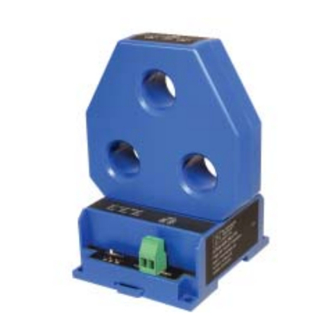
DT Series transducers combine a Hall Effect sensor and
a signal conditioner into a single package. This provides
higher accuracy, lower wiring costs, easier installation
and saves valuable panel space. DT Series are available
with 0-20 mA, 4-20mA, 0-5VDC or 0-10VDC outputs.
2. Using jumper select, choose the range that is equal to
or slightly higher than the nominal operating amperage.
3. Place the range jumper in the appropriate position.
1. OutputSignalTooLow
A. The jumper may be set in a range that is too high for
current being monitored. Move jumper to the correct
range.
B. Power supply is inadequate. Check power supply.
Make sure it is of sufficient voltage with all loads at
maximum. DT Series consumes 2.0 VA.
C. Output load too high on current output models.
Check output load, be sure it is no more than 500
Ω
.
Output load too low on voltageoutputmodels. Check
output load, be sure it is at least 10K
Ω
.
3.375 in.
(85.73m
m
)
DTC2-420-24U-FL
DC Current Transducer
MID HIGH
JUM PER RA NG E
NONE 5A
MID 10A
HIGH 50A
POWER
+-
4-20mA
Output
1234
Connection Information:
wTerminals 1 and 2: Power suppl
y
wTerminals 3 and 4: Output contr
o
wConnection wire capacity: 0.14
-
wScrew thread: M 3
wScrew torque: 0.5 - 0.6 Nm (4.4
Current direction
0-20mA&4-20mA:
The current loop is powered by the DT Transducer.
Maximumloopimpedanceis500Ω.
0-5VDC&0-10VDC:
Signal is powered by the DT Transducer. Minimum output
load(impedance) is 10K Ω.
CurrentDirection:
Ensure the direction of monitored current is the same as
the direction shown on the diagram. The unit will not
operate properly if the current is opposite the direction of
the arrow.
Note:
For power terminals 1 & 2 there is no assumed polarity,
either can be wired as positive (+) or negative (-).
2. OutputSignalisalwaysatmaximum
A. The jumper may be set in a range that is too low for
current being monitored. Move jumper to the correct
range.
3. Sensorhasnooutput
A. Polarity is not properly matched. Check and correct
wiring polarity.
B. Monitored load is not DC or is not on. Check that
the monitored load is DC and that it is actually on.

Other NK TECHNOLOGIES Transducer manuals
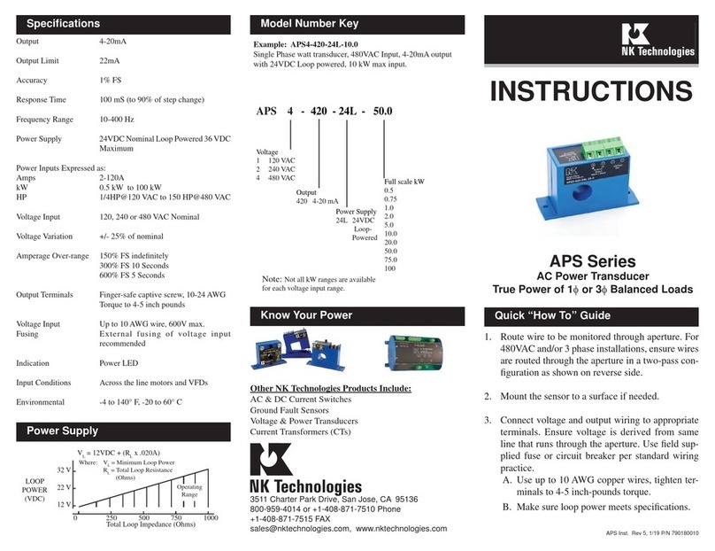
NK TECHNOLOGIES APS Series User manual
NK TECHNOLOGIES

NK TECHNOLOGIES APS Series User manual

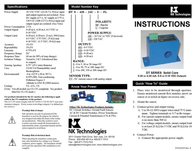
NK TECHNOLOGIES DT Series User manual

NK TECHNOLOGIES

NK TECHNOLOGIES DT Series User manual
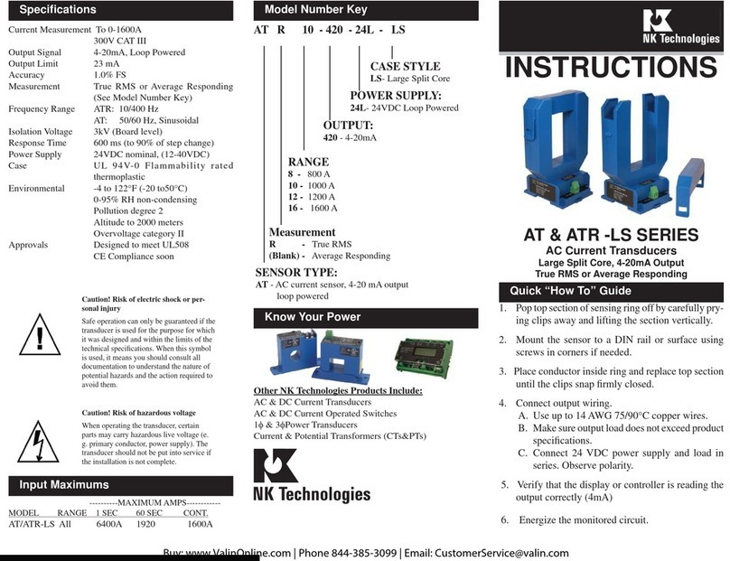
NK TECHNOLOGIES AT SERIES User manual

NK TECHNOLOGIES

NK TECHNOLOGIES AT SERIES User manual
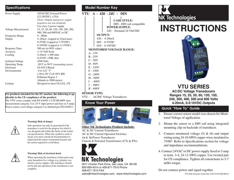
NK TECHNOLOGIES VTU Series User manual
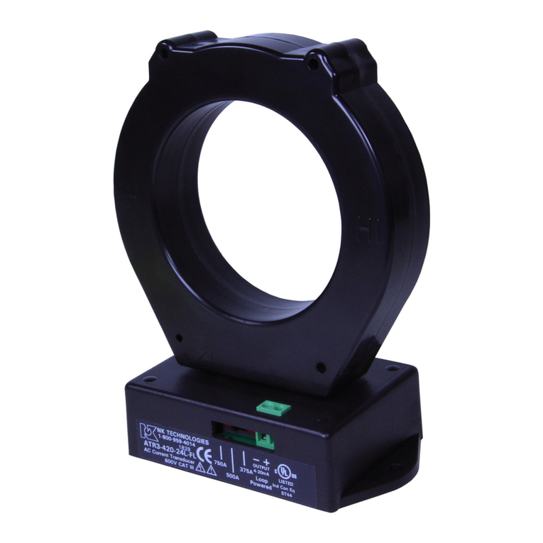
NK TECHNOLOGIES

NK TECHNOLOGIES VTU Series User manual

NK TECHNOLOGIES AT 2 Series User manual
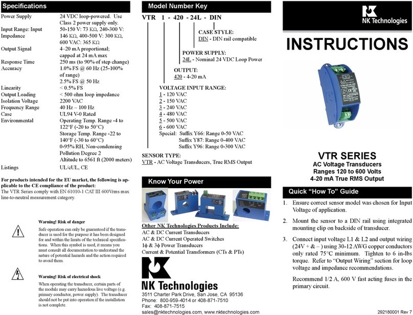
NK TECHNOLOGIES

NK TECHNOLOGIES AT 2 Series User manual

NK TECHNOLOGIES VTR Series User manual
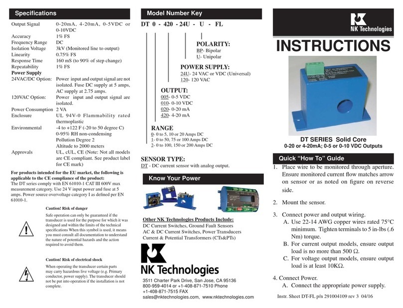
NK TECHNOLOGIES

NK TECHNOLOGIES VTR Series User manual

NK TECHNOLOGIES DT Series User manual

NK TECHNOLOGIES

NK TECHNOLOGIES DT Series User manual

NK TECHNOLOGIES APS Series User manual
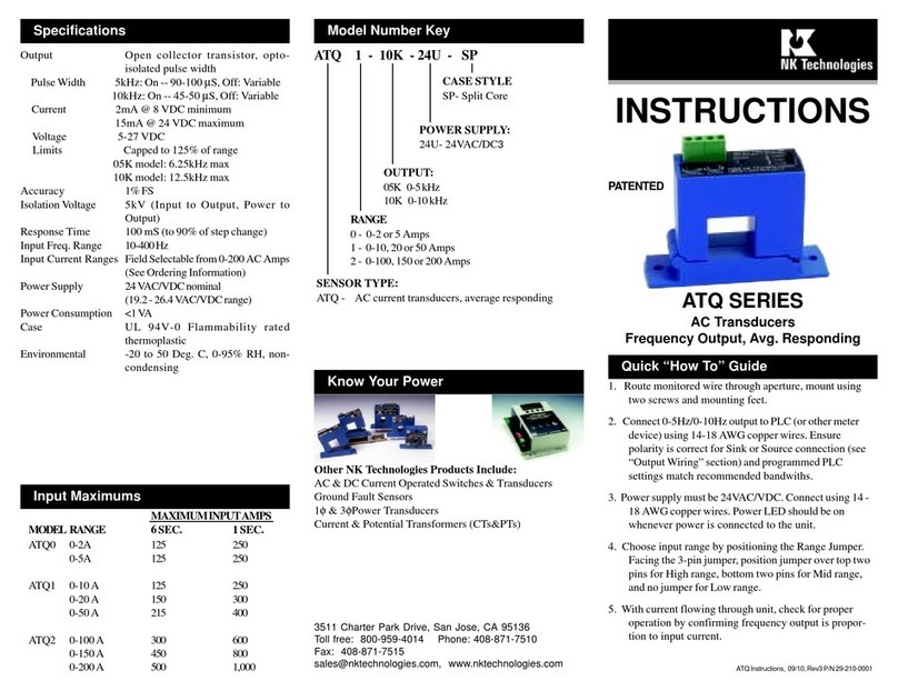
NK TECHNOLOGIES

NK TECHNOLOGIES APS Series User manual

NK TECHNOLOGIES ATQ Series User manual

NK TECHNOLOGIES

NK TECHNOLOGIES ATQ Series User manual

NK TECHNOLOGIES VTU Series User manual

NK TECHNOLOGIES

NK TECHNOLOGIES VTU Series User manual

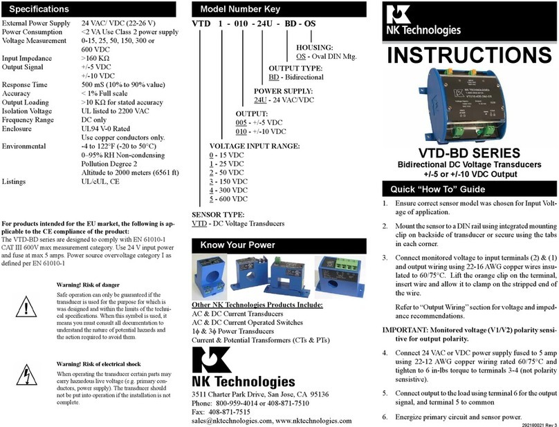
NK TECHNOLOGIES VTD-BD Series User manual

NK TECHNOLOGIES

NK TECHNOLOGIES VTD-BD Series User manual

NK TECHNOLOGIES AT-TH Series User manual

NK TECHNOLOGIES

NK TECHNOLOGIES AT-TH Series User manual

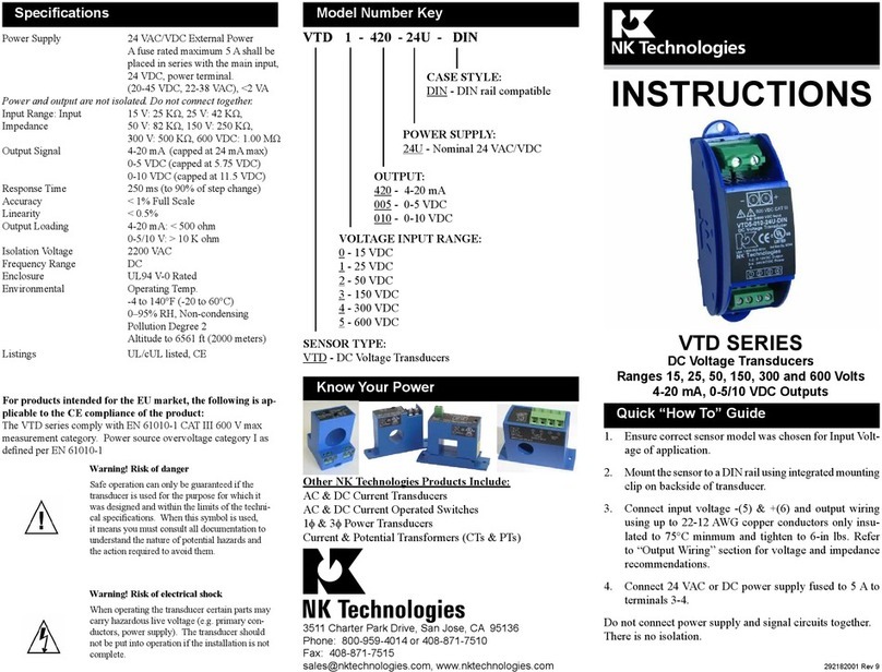
NK TECHNOLOGIES VTD Series User manual

NK TECHNOLOGIES

NK TECHNOLOGIES VTD Series User manual

Popular Transducer manuals by other brands
ITR SEM SC11 User manual and technical documentation
ITR

ITR SEM SC11 User manual and technical documentation

Balluff BIW1-A310-M -P1-S115 Series user guide
Balluff

Balluff BIW1-A310-M -P1-S115 Series user guide

Faget EM2020 Installation and start-up instructions
Faget

Faget EM2020 Installation and start-up instructions

WIKA WUD-2x-E operating instructions

WIKA

WIKA WUD-2x-E operating instructions

TR-Electronic LMP-30-300 PB manual

TR-Electronic

TR-Electronic LMP-30-300 PB manual
controlair 2000 Installation, operation and maintenance instructions
controlair

controlair 2000 Installation, operation and maintenance instructions

Simrad OUTLINE DIMENSIONS - SCHEMA REV B Dimensions
Simrad

Simrad OUTLINE DIMENSIONS - SCHEMA REV B Dimensions

domat PREMASGARD SHD Operating Instructions, Mounting & Installation
domat

domat PREMASGARD SHD Operating Instructions, Mounting & Installation

Hontzsch UVA-AS102 operating instructions
Hontzsch

Hontzsch UVA-AS102 operating instructions

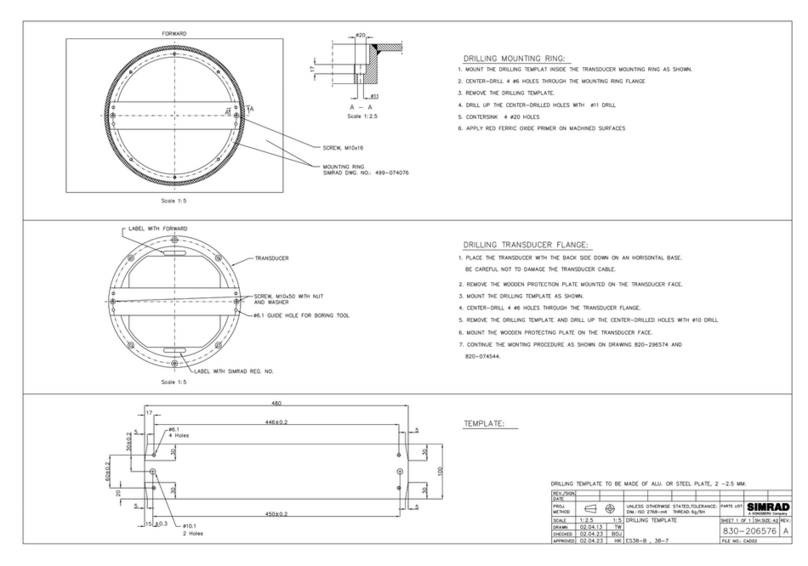
Simrad SUPPORT BEAM DRILLING TEMPLATE - SCHEMA REV... Template

Simrad

Simrad SUPPORT BEAM DRILLING TEMPLATE - SCHEMA REV... Template

Induction Dynamics SolidDrive SD1 Installation & use guide

Induction Dynamics

Induction Dynamics SolidDrive SD1 Installation & use guide

Balluff BTL7-V50T-M P-C003 Series user guide

Balluff

Balluff BTL7-V50T-M P-C003 Series user guide

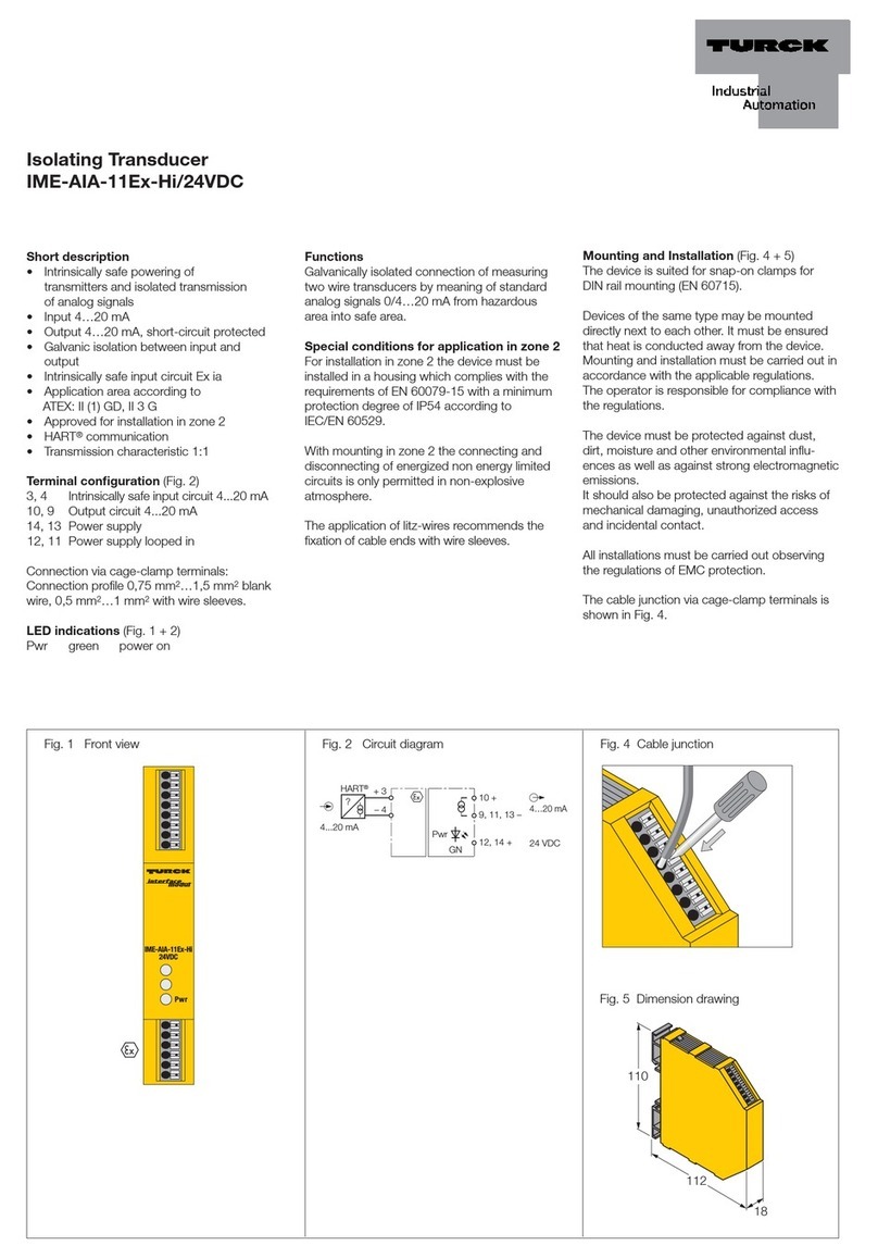
turck IME-AIA-11Ex-Hi/24VDC quick start guide

turck

turck IME-AIA-11Ex-Hi/24VDC quick start guide

Balluff BTL6-V11V-M Series manual

Balluff

Balluff BTL6-V11V-M Series manual

Woodward UMT 1 manual

Woodward

Woodward UMT 1 manual

Shinkawa FK-152R operating instructions

Shinkawa

Shinkawa FK-152R operating instructions

novotechnik TMI Series manual

novotechnik

novotechnik TMI Series manual

Simrad ES 18 - DATASHEET REV C datasheet

Simrad

Simrad ES 18 - DATASHEET REV C datasheet

manuals.online logo
manuals.online logoBrands
  • About & Mission
  • Contact us
  • Privacy Policy
  • Terms and Conditions

Copyright 2025 Manuals.Online. All Rights Reserved.