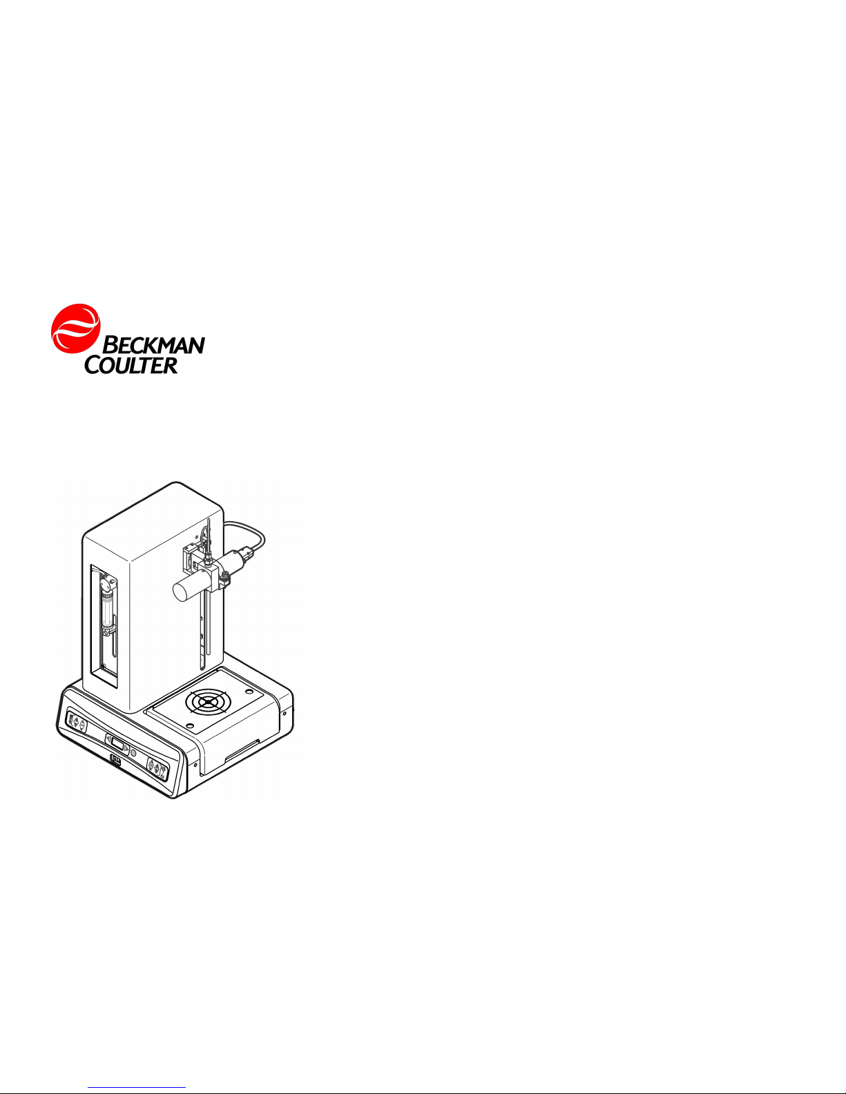
Beckman Coulter HIAC 9703+ User manual
DOC026.98.80097
HIAC 9703+ Liquid Particle
Counter
10/2013, Edition 5
User Manual
Bedienungsanleitung
Manuale d'uso
Manuel d'utilisation
Manual del usuario

English...................................................................................................................................................................................................3
Deutsch...............................................................................................................................................................................................21
Italiano.................................................................................................................................................................................................39
Français..............................................................................................................................................................................................57
Español...............................................................................................................................................................................................75
2
Specifications
Specifications are subject to change without notice.
Specification Details
Dimensions (W x D x H) 343 x 337 x 482 mm (13.5 x 13.3 x 19.0 in.)
Weight 10.7 kg (23.6 lb)
Power requirement External Class III power adapter:
100–240 VAC, 50–60 Hz, 2.5 A input;
24 VDC, 3.75 A output
Instrument: 24 VDC, 75 W maximum
Viscosity limits < 50 cp
Coincidence loss limit 7,500
Operating temperature 5 °C to 40 °C (41 °F to 104 °F)
Operating humidity 0 to 80% relative humidity for temperatures
up to 31 °C decreasing linearly to 50% RH at
40 °C
Maximum altitude 2,000 m (6,560 ft)
Sample bottle clearance 153 mm (6.02 in.)
Sample temperature 5 °C to 40 °C (41 °F to 104 °F)
Flow rate 10 to 100 mL/min (determined by the sensor
calibration flow rate)
Flow rate accuracy > 95%
Volume accuracy > 95% of syringe size1
Tare volumes for probes
0.091 mL for 8.1 cm (3.2 in.)/1.2 mm
(0.047 in.) ID
0.172 mL for 15.4 cm (6.1 in.)/1.2 mm
(0.047 in.) ID
1.57 mL for 14 cm (5.5 in.)/large bore
Specification Details
Sensor concentration limits
(particle per ml)
HRLD150: 18,000
HRLD150JA: 18,000
HRLD400: 10,000
HRLD600JS: 6,000
MC05: 9,000
Wetted materials PTFE Teflon®, TFE Teflon, PFA Teflon, Kel-F,
316 Stainless steel, Glass, Viton®
Number of channels 4 (2 for light scatter, 2 for light extinction)
Number of bins 65,536 (16,384 bins per channel)
Certification CE
1Under ideal conditions, inaccuracy in flow rate is ≤1% of syringe size.
General information
In no event will the manufacturer be liable for direct, indirect, special,
incidental or consequential damages resulting from any defect or
omission in this manual. The manufacturer reserves the right to make
changes in this manual and the products it describes at any time, without
notice or obligation. Revised editions are found on the manufacturer’s
website.
Safety information
NOTICE
The manufacturer is not responsible for any damages due to misapplication or
misuse of this product including, without limitation, direct, incidental and
consequential damages, and disclaims such damages to the full extent permitted
under applicable law. The user is solely responsible to identify critical application
risks and install appropriate mechanisms to protect processes during a possible
equipment malfunction.
Please read this entire manual before unpacking, setting up or operating
this equipment. Pay attention to all danger and caution statements.
English 3
Failure to do so could result in serious injury to the operator or damage
to the equipment.
Make sure that the protection provided by this equipment is not impaired.
Do not use or install this equipment in any manner other than that
specified in this manual.
Use of hazard information
DANGER
Indicates a potentially or imminently hazardous situation which, if not avoided, will
result in death or serious injury.
W A R N I N G
Indicates a potentially or imminently hazardous situation which, if not avoided,
could result in death or serious injury.
CAUTION
Indicates a potentially hazardous situation that may result in minor or moderate
injury.
NOTICE
Indicates a situation which, if not avoided, may cause damage to the instrument.
Information that requires special emphasis.
Precautionary labels
Read all labels and tags attached to the instrument. Personal injury or
damage to the instrument could occur if not observed. A symbol, if noted
on the instrument, will be included with a danger or caution statement in
the manual.
This symbol, if noted on the instrument, references the instruction
manual for operation and/or safety information.
This symbol indicates that a risk of electrical shock and/or
electrocution exists.
This symbol indicates the presence of devices sensitive to Electro-
static Discharge (ESD) and indicates that care must be taken to
prevent damage with the equipment.
This symbol indicates a laser device is used in the equipment.
This symbol indicates the need for protective eye wear.
This symbol indicates a potential pinch hazard.
Electrical equipment marked with this symbol may not be disposed of
in European public disposal systems after 12 August of 2005. In
conformity with European local and national regulations (EU Directive
2002/96/EC), European electrical equipment users must now return
old or end-of-life equipment to the Producer for disposal at no charge
to the user.
Certification
Canadian Radio Interference-Causing Equipment Regulation,
IECS-003, Class A:
Supporting test records reside with the manufacturer.
This Class A digital apparatus meets all requirements of the Canadian
Interference-Causing Equipment Regulations.
Cet appareil numérique de classe A répond à toutes les exigences de la
réglementation canadienne sur les équipements provoquant des
interférences.
FCC Part 15, Class "A" Limits
Supporting test records reside with the manufacturer. The device
complies with Part 15 of the FCC Rules. Operation is subject to the
following conditions:
4 English
1. The equipment may not cause harmful interference.
2. The equipment must accept any interference received, including
interference that may cause undesired operation.
Changes or modifications to this equipment not expressly approved by
the party responsible for compliance could void the user's authority to
operate the equipment. This equipment has been tested and found to
comply with the limits for a Class A digital device, pursuant to Part 15 of
the FCC rules. These limits are designed to provide reasonable
protection against harmful interference when the equipment is operated
in a commercial environment. This equipment generates, uses and can
radiate radio frequency energy and, if not installed and used in
accordance with the instruction manual, may cause harmful interference
to radio communications. Operation of this equipment in a residential
area is likely to cause harmful interference, in which case the user will be
required to correct the interference at their expense. The following
techniques can be used to reduce interference problems:
1. Disconnect the equipment from its power source to verify that it is or
is not the source of the interference.
2. If the equipment is connected to the same outlet as the device
experiencing interference, connect the equipment to a different
outlet.
3. Move the equipment away from the device receiving the interference.
4. Reposition the receiving antenna for the device receiving the
interference.
5. Try combinations of the above.
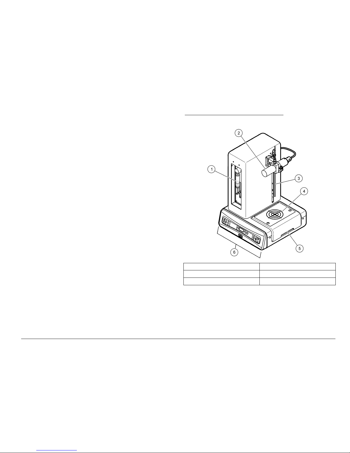
Product overview
The HIAC 9703+ liquid particle counter system measures particles in a
variety of liquids with a syringe sampler and sensor. The instrument
must connect to a computer for operation and data management. Refer
to Figure 1 and Figure 2.
An external sensor is used with the HIAC 9703+ liquid particle counter
system. Refer to Figure 1, item 2. The external sensors are classified as
Class 1 Laser Products. Refer to the sensor manual for FDA and IEC
compliance.
Figure 1 HIAC 9703+ liquid particle counter
1 Syringe 4 Sample target
2 Sensor 5 Docking module
3 Sample probe 6 Front panel
English 5
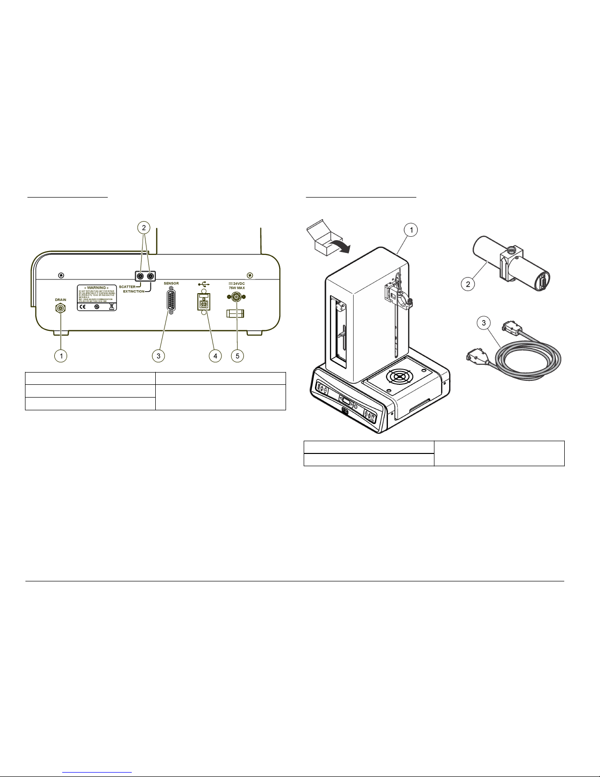
Figure 2 Back panel
1 Drain fitting 4 USB connector
2 Service-only ports 5 Power connector
3 Sensor connector
Product components
Make sure that all components have been received. Refer to Figure 3,
Figure 4 and Figure 5. If any items are missing or damaged, contact the
manufacturer or a sales representative immediately.
Figure 3 HRLD components
1 HIAC 9703+ liquid particle counter 3 Cable, sensor
2 Sensor, HRLD
6 English

Figure 4 MC05 components
1 HIAC 9703+ liquid particle counter 2 Sensor, MC05
Figure 5 Shipping kit
1 Nut 7 Probe, small bore
2 Hex Key, 1.5 mm 8 Cable, USB
3 Syringe, 10 ml 9 Power supply, 24V
4 Power cord, AC 10 O-rings
5 Stir Bar, Teflon 11 Tubing
6 Probe, large bore 12 Power cord, European
English 7
Installation
W A R N I N G
Electrical shock hazard. Externally connected equipment must have an
applicable country safety standard assessment.
CAUTION
Multiple hazards. Only qualified personnel should conduct the tasks
described in this document.
Site location
Position the instrument on a dry, level surface. The location must be
indoors and near an electrical outlet and a computer. Make sure the
power switch is accessible.
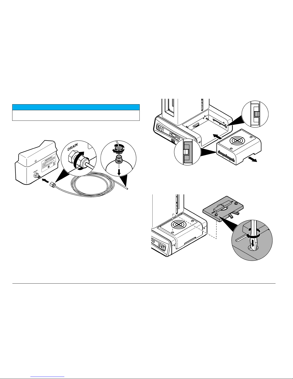
Install the HRLD sensor
The sensor is held in place by the holding arm. A sampling probe and
tubing must connect to the sensor for sample flow. A cable must connect
to the sensor for signal transmission. To install the sensor, refer to the
illustrated steps.
Note: Do not put Teflon tape on the fitting threads.
8 English

English 9

10 English

Install the MC05 sensor
The sensor is held in place by the holding arm. A sampling probe and
tubing must connect to the sensor for sample flow. A cable must connect
to the sensor for signal transmission. To install the sensor, refer to the
illustrated steps.
Note: Do not put Teflon tape on the fitting threads.
English 11

12 English

English 13
Connect the drain line
NOTICE
Dispose of waste in accordance with local, state and national environmental
regulations.
The sample waste from the instrument must be collected in a compatible
waste container. Monitor the liquid level in the waste container to prevent
overflow.
Install or remove the docking module
Docking modules are available for single or multiple-container sampling.
Install the small-vial clamp
The optional small-vial clamp connects to the docking module with
2 screws.
14 English
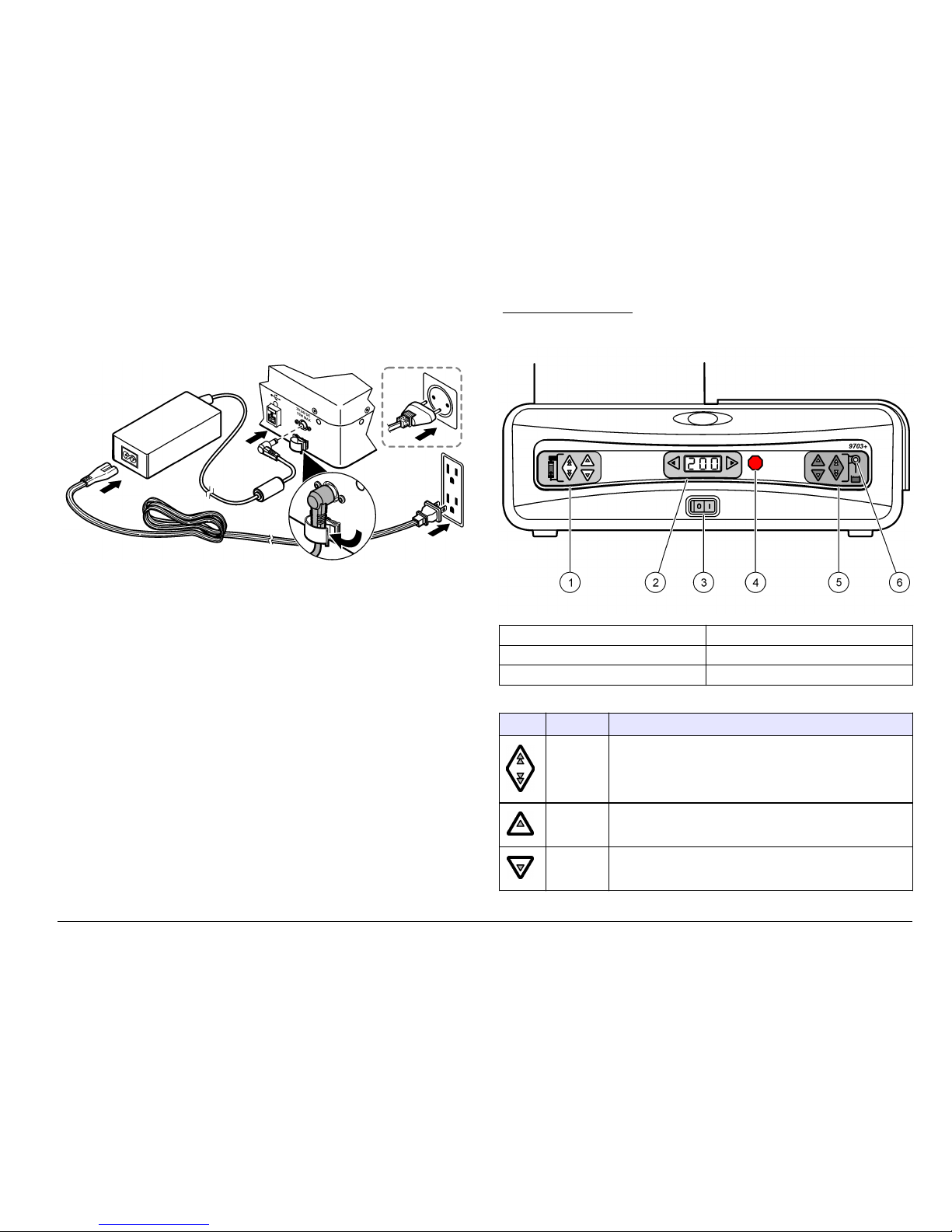
Connect the power cord
A power supply unit is used to supply power to the instrument.
Remove the magnetic stirrer
The magnetic stirrer in the docking module can be removed if necessary.
1. Pull the tab on the docking module away from the instrument to
remove the module.
2. Remove the four screws on the bottom plate of the module. Separate
the bottom plate from the module enclosure.
3. Remove the screw that holds the magnet to the motor shaft. Hold the
shaft with pliers so that the shaft does not move.
4. Remove the magnet and install the screw. Hold the shaft with pliers
so that the shaft does not move.
5. Put the bottom plate on the module enclosure and install the four
screws.
User interface
The buttons on the front panel allow the user to operate the syringe,
sample probe and stirrer. Refer to Figure 6, Table 1 and Table 2.
Figure 6 Front panel
1 Syringe controls 4 Stop button
2 Stirrer speed (RPM) 5 Sample probe controls
3 Power switch 6 LED status indicators
Table 1 Button descriptions
Button Name Description
Load Sends the syringe plunger to the top or bottom position.
Clean Flushes the system.
Back-flush Back-flushes the system when held for 3 seconds.
English 15

Table 1 Button descriptions (continued)
Button Name Description
Stop Stops the movement of the syringe and probe. Sampling is
stopped. The stirrer continues to operate.
Set Moves the sample probe up or down. Hold to increase
speed.
Lift/Lower Sends the sample probe to the top or bottom position.
Table 2 LED status indicators
LED color Description
Green Instrument is powered on
Yellow Instrument is sampling
Flashing yellow Shows the boot up sequence
Operation
DANGER
Fire hazard. This product is not designed for use with flammable
liquids.
W A R N I N G
Explosion hazard. Make sure that the drain tube is free of all
obstructions. If the drain tube has a blockage or is pinched or bent,
high pressure can build up in the instrument.
CAUTION
Chemical exposure hazard. Obey laboratory safety procedures and
wear all of the personal protective equipment appropriate to the
chemicals that are handled. Refer to the current safety data sheets
(MSDS/SDS) for safety protocols.
Turn the instrument on or off
When power is applied to the instrument, the sampling probe
automatically moves to the top position and the magnetic stirrer starts.
The display on the front panel shows the stirrer speed in RPM.
1. Make sure that there are no obstructions to the movement of the
probe.
2. Push the ON/OFF switch to turn the instrument on or off.
Note: Push the STOP button to immediately stop the movement of the syringe
and sample probe.
Attach the syringe
The syringe drive mechanism must be at the bottom position to attach or
remove the syringe.
16 English

Figure 7 Attach the syringe
1 Plunger bolt 3 Syringe drive
2 Syringe 4 Valve
1. Push the ON/OFF switch to turn the instrument on.
2. Push the LOAD button under the syringe compartment to set the
plunger bolt at the lowest point. Refer to Figure 7.
3. Loosen and remove the plunger bolt from the syringe drive.
4. Hold the syringe and push the bolt through the plunger hole.
5. Push the bolt in the syringe drive hole and turn the bolt by hand to
tighten.
6. Pull the syringe barrel up and install the syringe threads in the valve.
7. Turn the syringe by hand to tighten.
Note: Do not overtighten.
Set the sample probe position
The lift mechanism for the sample probe can be set to automatically go
to the correct position for sampling.
English 17

1. Put a sample container on the module. If a small vial is used, refer to
Put a vial in the small-vial clamp on page 18.
2. Push the SET button to lower the sample probe to the correct
position.
3. Push the LIFT/LOWER button to raise the sample probe to the top
position.
4. Push the LIFT/LOWER button to automatically move the sample
probe down and stop at the correct bottom position.
Note: This position is recognized by the external software.
The bottom position is saved until a new bottom position is set.
Flush the syringe
Flush the syringe when a new syringe is installed or when a new sample
is used. To optimize the performance of the syringe:
• Do not operate the syringe for more than a few cycles without liquid.
• Thoroughly flush the syringe with distilled or deionized water after use.
1. Push the LIFT/LOWER button to raise the sample probe.
2. Put the container with the flushing liquid under the sample probe.
3. Push the LIFT/LOWER button to lower the sample probe in the
flushing liquid.
4. Push the CLEAN button. The syringe fills with the flushing liquid and
pushes the liquid out to the drain.
Note: The system can also be flushed with the external software.
Put a vial in the small-vial clamp
The small-vial clamp holds small vials under the center of the sample
probe. To install the clamp assembly, refer to Install the small-vial clamp
on page 14.
Stop all operations
The STOP button can be used to simultaneously stop movement of the
syringe and sample probe. Use the buttons or external software to
resume operations.
Connect the computer cable
A USB cable connects the instrument to a computer.
1. Install a compatible software application on the computer.
2. Turn on the instrument power.
3. Connect the USB cable to the USB port on the instrument and to the
computer.
Operate the instrument by computer
The instrument must connect to a computer for configuration, calibration,
data collection and data management. Refer to the software user
manual for specific instructions.
18 English

Maintenance
CAUTION
Personal injury hazard. Only qualified personnel should conduct the tasks
described in this section of the manual.
NOTICE
Do not disassemble the instrument for maintenance. If the internal components
must be cleaned or repaired, contact the manufacturer.
Clean the instrument
Clean the exterior of the instrument with a moist cloth and a mild soap
solution and then wipe the instrument dry.
Clean the syringe
Frequent use and dirty sample material make it necessary to clean the
syringe more often. Clean the syringe daily or weekly to make sure that it
works properly. Use a mild detergent for standard applications. To find
whether a different cleaning solution is compatible with the instrument,
refer to Specifications on page 3.
1. Put a container with the cleaning solution on the docking module.
2. Push the LIFT/LOWER button to lower the sample probe.
3. Push the LOAD button to fill the syringe with the cleaning solution.
Note: If the plunger does not move easily in the syringe barrel, remove the
plunger, wipe the plunger with alcohol and wet the plunger seal with deionized
water.
4. Allow the solution to stay in the syringe for a minimum of 30 minutes.
5. Push the LOAD button to send the cleaning solution to the drain.
6. Push the LIFT/LOWER button to raise the sample probe.
7. Put a container with distilled or deionized water on the docking
module.
8. Push the LIFT/LOWER button to lower the sample probe.
9. Push the CLEAN button to flush the syringe with the rinse water.
10. Repeat the flush with rinse water for a minimum of 10 cycles.
Troubleshooting
Back-flush the system
A large particle can reduce or stop the liquid flow. If this occurs, a flush
in the reverse direction can push the particle out through the sample
probe.
1. Put a small waste container under the sample probe.
2. Push the LIFT/LOWER button to lower the sample probe.
3. Push and hold the BACK-FLUSH button until the back-flush cycle
starts.
The syringe fills with liquid from the drain tubing. When the syringe
closes, the liquid is sent through the sensor and sample probe.
4. Repeat the back-flush cycle as necessary until a flush in the forward
direction with a clean sample flows at a normal rate.
How to clean spills
CAUTION
Chemical exposure hazard. Dispose of chemicals and wastes in
accordance with local, regional and national regulations.
1. Obey all facility safety protocols for spill control.
2. Discard the waste according to applicable regulations.
Replacement parts and accessories
W A R N I N G
Personal injury hazard. Use of non-approved parts may cause
personal injury, damage to the instrument or equipment malfunction.
The replacement parts in this section are approved by the
manufacturer.
Note: Product and Article numbers may vary for some selling regions. Contact the
appropriate distributor or refer to the company website for contact information.
English 19

Replacement parts
Description Item no.
Cable, USB, 2 m 460-400-4799
Fitting, probe to HRLD sensor 90630002
O-rings, sensor, pkg/4 808-010-200
Power cord, 230 VAC, 1.8 m (6 ft) VP623500
Power cord, 115 VAC, 1.8 m (6 ft) VP623501
Power supply 230-300-7052
Sampling probe, 14 cm (5.5 in.), large bore 90620008
Sampling probe, 15.4 cm (6.1 in.), 1.2 mm (0.047 in.) ID 90450001
Stir bar, Teflon, pkg/5 600-100-0003
Syringe, 10-mL 690-300-4808
Tubing Assy, drain 089208-01
Modified coupling 047156-03
Accessories
Description Item no.
Cleaning floss 660-850-0001
Small vial sampling kit (includes 2089099-01,
90450004 and 690-300-4805) 2089006-01
Module, small-vial clamp 2089099-01
Sampling probe, 8.1 cm (3.2 in.), 1.2 mm (0.047 in.) ID 90450004
Syringe, 1-mL 690-300-4805
Syringe, 25-mL 690-300-4809
HRLD Sensor holder 2089290-01
Accessories (continued)
Description Item no.
MC05 Sensor holder 2089291-01
Cable, HRLD to 9703+, 0.9 m (3 ft) 2089179-01
20 English
Table of contents
Languages:
Other Beckman Coulter Cash Counter manuals


Popular Cash Counter manuals by other brands


Kübler
Kübler CODIX 521 operating instructions

Leader Electronics Corp.
Leader Electronics Corp. LDC-824 instruction manual

DIEBOLD NIXDORF
DIEBOLD NIXDORF DN Series 100D FL operating manual

Nautilus Hyosung
Nautilus Hyosung MS500 Operator's manual

PASCO
PASCO SN-7927A instruction sheet

Milesight
Milesight VS133-P user guide


