5
Note
Not required for wall-surface installation
Shielded cable
CVVS, MVVS: 1.25 mm²~2 mm² (AWG16~14)
CPEVS: Ø1.2 mm~Ø1.6 mm (AWG16~14 or their equivalents)
Qty.
1
As appropriate
As appropriate
As appropriate
Parts
Triple electric box
Thin metal conduit
Lock nut and bushing
M-NET cable
The figure below shows the M-NET transmission wiring diagram for City Multi air conditioners.
The maximum length of centralized control M-NET transmission line and the indoor-outdoor transmission line per system can be
expressed in the following formulas. Labels "a through g" represent the sections of wiring in the system in the figure below. These
limits ensure normal signal communication over the M-NET transmission line.
If the line length exceeds the maximum length, M-NET signal attenuation can occur, rendering normal communication and control
impossible.
a+b+d+e(f) ≤ 500 m (1640 ft) a+b+c+g ≤ 500 m (1640 ft) e(f)+d+c+g ≤ 500 m (1640 ft)
The maximum length of local remote controller cable is 10 m (32 ft). The length that exceeds 10 m (32 ft) must be included in the
maximum total line length 500 m (1640 ft).
ac
edb
f
g
Outdoor
unit
Outdoor
unit
Indoor unit Indoor unit
Indoor unit
Indoor unit Indoor unit
Power supply
unit for transmission
cable
System
controller
Indoor-outdoor
transmission line
10 m (32 ft)
Centralized controller
transmission line
M-NET
remote
controller
5 Installation
1. Field-supplied parts
The following parts are required to install the controller.
2. Required tools
•A knife or nippers •Crosshead driver
3. Installation methods
Follow the instructions provided for the selected installation option.
(a) Wall-embedded installation using an electric box
(b) Wall-surface installation
(b-1) To route the cable through the wall
(b-2) To route the cable along the wall surface
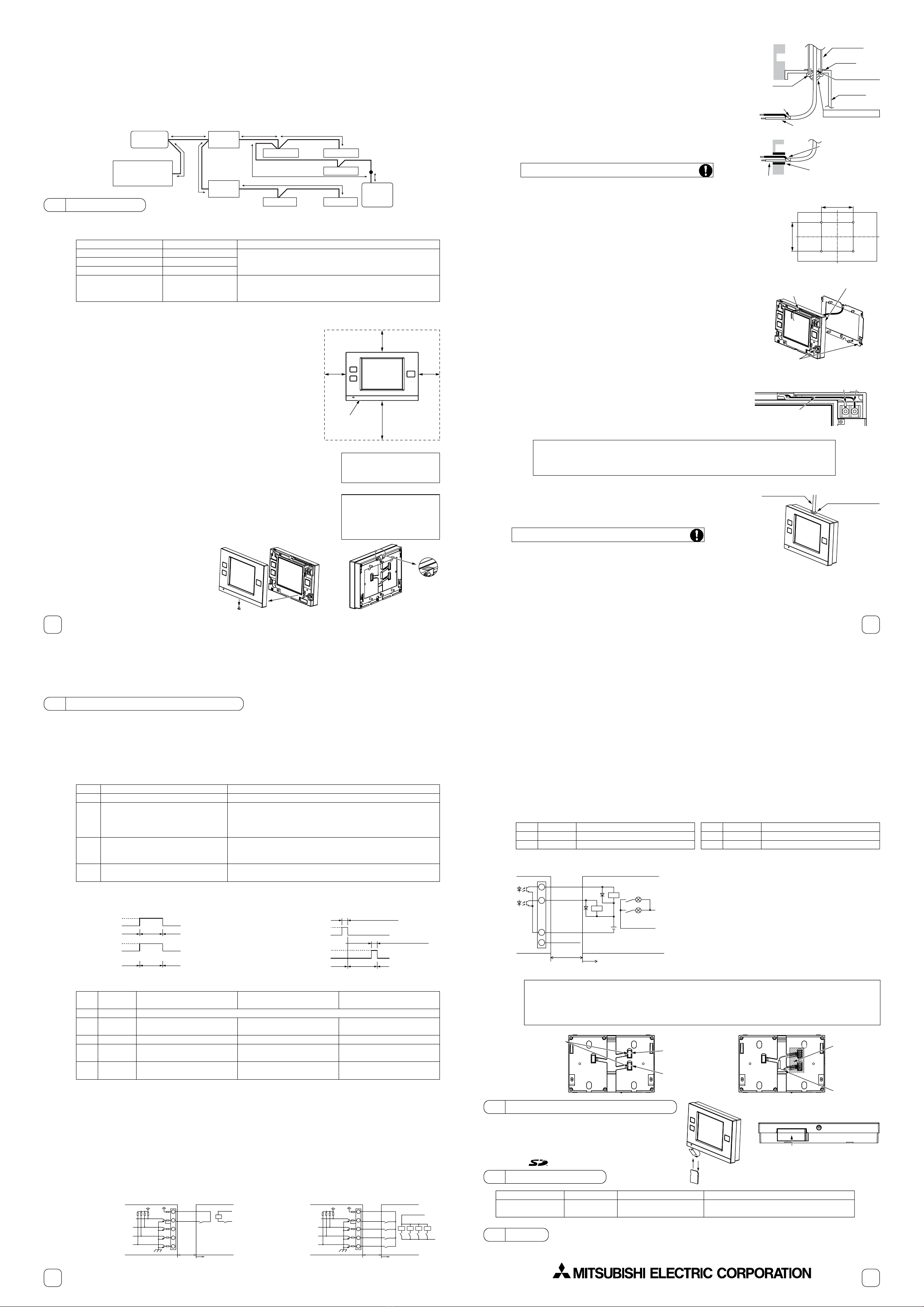
4. Preparation
(1) Install a breaker on the power supply unit side before installing the controller.
(2) Select an installation site for the Touch Controller.
• Install the controller at the user's eye level for easy operation.
• Ensure there is enough clearance space as shown in the figure at right.
• Ensure there is enough clearance space to allow for easy access to the panel and the
buttons.
(3) Bring the cable end up to the controller.
Ensure the M-NET transmission cables and external input/output cables are long enough to
reach the controller. Have extra cables to extend these cables as necessary.
• To install the controller according to the instructions provided in sections (a) and (b-1) above
Include an extra 30 cm (12 in) of cable to provide adequate slack in the cable.
Remove the sheath on the M-NET transmission cable up to 20 cm (8 in) from the end.
• To install the controller according to the instructions provided in section (b-2) above
Include an extra 15 cm (6 in) of cable to provide adequate slack in the cable.
Remove the sheath on the M-NET transmission cable up to 10 cm (4 in) from the end.
(4) Prepare the Touch Controller.
Unscrew the screw at the bottom of the
controller, and remove the cover.
To route the cable along the wall surface, cut
out the rectangle knockout hole (18 mm (W)
x 9 mm (D)) at the top of the controller with a
knife or a nipper (shown as the shaded area
in the figure below at right).
30
(1.3/16)
30 (1.3/16)
50 (2)
Unit: mm (in)
Refer to section 6 "External input
output" for how to connect external
input/output signal cables.
Note
Do not push the shield wire into
or connect it to the TC-24A. Trim
the shield wire, cover it with vinyl
insulating tape, and leave it outside
the controller.
Note
30
(1.3/16)
Touch controller
outline
6
5. Installation steps
(1) Routing the cables
(a) Wall-embedded installation using an electric box
Pull the M-NET transmission cable through the hole on the wall and the electric
box, and seal the gap between the cable and the end of the conduit tube.
(b) Wall-surface installation
•To route the cable through the wall :
Drill a hole in the wall, push the M-NET transmission cable through the hole, and
seal the gap between the cable and the hole with putty.
•To route the cable along the wall surface :
It is approximately 10 cm (4 in) from the cable access hole on the back of TC-24A
to the M-NET terminal block. Trim off the excess transmission cable, if any.
(2) Attach the mounting bracket on the wall.
Attach the mounting bracket on the designated area on the wall using the supplied
screws.
The pitch for the mounting bracket is shown in the figure at right.
(3) Attach the controller to the mounting bracket.
After inserting the M-NET transmission cables (A and B) through the cable access hole
on the controller from the back, hang the controller on the hooks of the mounting
bracket.
Attach the controller to the mounting bracket using twenty M4 screws with spring
washers/washers.
(4) Connect the cables.
Connect the M-NET transmission cables (A and B) to the terminal block. M-NET
transmission cable is non-polarized.
Insert the cables in the groove on the controller so they will not be pinched when
the cover is installed.
(5) Replace the cover.
Snap the cover into place, and attach it to the controller with a screw at the bottom.
*Tighten the screw to a torque of 10 N·m or less.
*To route the cable along the wall surface
Secure the cables in place with a cable cover, and seal the gap between the cable cover
and the controller with putty.
• The M-NET terminal on the controller is only for connection to the M-NET cable.
Do not connect an AC power supply.
• Do not daisy-chain M-NET terminals.
Note
To reduce the risk of electric shock, malfunctions, or fire, seal the
gap between the cables and access holes with putty.
Wall Remove the sheath,
and insulate the
shield wire with vinyl tape.
M-NET transmission cable
A , B
Seal the gap with putty.
Cable access hole
Hang the controller on the
hooks of the mounting bracket.
Screw the controller
on the bracket.
Insert the cable into the groove.
M-NET transmission cable
(non-polarized)
A B
Use a cable cover.
Seal the gap with putty.
92 (3.5/8)
83.5 (3.5/16)
Unit: mm (in)
To reduce the risk of electric shock, malfunctions, or fire, seal the
gap between the cables and access holes with putty.
Conduit tube
Electric box
Bushing
M-NET transmission cable
A , B
Remove the sheath,
and insulate the
shield wire with
vinyl tape.
Locknut
Wall
Cable access hole
Seal the gap with putty.
7
Mode
1
2
3
4
External input signal setting
Do not use external input. (Factory setting)
Emergency stop/Normal operation signal
(level signal)
ON/OFF signal (level signal)
ON/OFF and Prohibit/Permit remote
controller operation signal (pulse signal)
Notes
-
When the units are not operating after receiving an emergency stop signal,
the ON/OFF operation from the local remote controller will not be allowed,
and the ON/OFF and Prohibit/Permit settings on the Touch Controller
cannot be changed. Timer operation will not function.
ON/OFF operation from the local remote controller will not be allowed, and
the ON/OFF and Prohibit/Permit settings on the Touch Controller cannot
be changed. Timer operation will not function.
The ON-signal pulse width should be set to a value between 0.2 and 1
seconds.
6 Usingexternal input/output
1. External signal input (CN2)
*To use external input, an external input/output adapter (PAC-YT41HAA; sold separately) is required.
(1) External input
Using external dry contact signals, the following operation of all air conditioning units can be controlled from the Touch Controller:
Emergency stop/Normal operation, ON/OFF, Permit/Prohibit local remote controller operation. These settings are made on the
External Input Settings on the Initial Settings screen that is accessible from the Service Menu screen. (Refer to Chapter 3 in the Initial
Setting Manual.)
(3) External input specifications
(A) Level signal
• tIf the type of signal assigned to the external input contact is "Emergency/Normal," the units in normal operation will stop when
the signal input changes from OFF to ON. Conversely, the units that are stopped will resume normal operation when the signal
changes from ON to OFF. After the emergency stop is reset, the original operating status of each air conditioning unit will not be
automatically restored. The air conditioning units must be started up manually.
• If the type of signal assigned to the external input contact is "ON/OFF," the units that are stopped will start operation after the
input signal changes from OFF to ON. Conversely, the units that are in operation will stop after the input signal changes from
ON to OFF.
(B) Pulse signal
• If the incoming signal is the same as the signal that is currently being received, no status change will occur.
• If local remote controller operation is prohibited, ON/OFF status, operation mode, or temperature setting cannot be changed and
filter sign cannot be reset from the remote controller.
• The ON-signal pulse width should be set to a value between 0.2 and 1 seconds.
(4) Sample circuit recommended
(A) Level signal (B) Pulse signal
(2) Level signal and pulse signal
CN2
1
2
3
4
5
Lead wire
Green
Yellow
Orange
Red
Brown
Emergency stop/Normal
operation signal (level signal)
Emergency stop/Normal
operation signal input
Not used
Not used
Not used
Built-in 5 VDC power for external input * Exclusively for use with external input. Not usable for other purposes.
ON/OFF level signal
ON/OFF signal input
Not used
Not used
Not used
ON/OFF, Prohibit/Permit remote
controller operation (pulse signal)
ON signal input
OFF signal input
Prohibit-local-remote-controller-
operation signal input
Permit-local-remote-controller-
operation signal input
(ex.)ON/OFF
Signal 1 (ON)
Signal 2 (OFF)
*Same for Prohibit/Permit remote controller operation.
OFF
Contact ON
Contact OFF OFFON
Normal
operation
Contact ON
Contact OFF
Normal
operation
Emergency
stop
Contact ON
Contact OFF
OFF
Contact ON
Contact OFF OFFON
0.2 to 1 seconds
0.2 to 1 seconds
(A) Level signal (B) Pulse signal
CN2
ON/OFF
or Emergency stop
Green
Yellow X1
Touch Controller
Maximum
10 m
(32 ft)
X1
X1 X2 Y1 Y2
1
2
3
4
5
ON
OFF Permit
Prohibit
CN2 Green
Yellow X1
Touch Controller
Maximum
10 m
(32 ft)
Orange X2
Red Y1
Y2
Brown
1
2
3
4
5
Field supplied Field supplied
8
•The relays and extension cables are field supplied.
•Use a no-voltage contact and minute load relay (minimum application load 5VDC-1mA).
•The length of the connection cable extension should not exceed 10 m (32 ft). (Use a cable of 0.3 mm² (22AWG) or thicker.)
•Insulate the area with vinyl tape where the controller cable and the extension cable are connected.
•Insulate the end of unused lead wires with tape.
2. External signal output
*To use external output, an external input/output adapter (PAC-YT41HAA; sold separately) is required.
Requires a separate external power source.
(1) External signal output (CN3)
Operation signal will be output when one or more air conditioning units are in operation, and error signal will be output when one or
more units are in error.
The On-signal will be output even during an error.
(2) External output specifications
(3) Sample circuit recommended
Relay-driven circuit
CN3
1
2
Lead wire
Brown
Red
Signal
ON/OFF
Error/Normal
CN3
3
4
Lead wire
Orange
Yellow
Signal
Ground for all external outputs
Not used
Parts
External input/output
adapter
Model
PAC-YT41HAA
Usage
Enables the use of external
input/output function
Note
Required to use the external input/output function
5-wire cable (input) , 4-wire cable (output)
CN3 Diode (*2)
Power source
(*1)
Z1
Z2
L1
L2
Red
Brown
Orange
Yellow
Touch Controller
2
1
3
4
Maximum
10 m
(32 ft)
Z2
Z1
L1 : Operation indicator
L2 : Error indicator
Use relays that meet the following specifications for relays indicated as Z1
and Z2 in the figure.
Operating coil
Rated voltage:12 VDC or 24 VDC
Power consumption: 0.9 W or below
(*1) Select a power supply suitable for the relays used. (12 VDC or 24 VDC)
(*2) Use a diode at each end of the relay coil.
• Each element will turn on when an error occurs during operation.
• The maximum length of extension cable is 10 m (32 ft). (Use a cable of
0.3 mm² (22AWG) or thicker.)
• Insulate the area with vinyl tape where the controller cable and the
extension cable are connected.
• Relays, lamps, diode, extension cables are field-supplied.
●To connect cables from an external input/output adapter to connectors CN2 and CN3 on the controller, cut out the appropriate
knockout holes on the controller with nippers.
After connecting the cables to the connectors, hold the cables in place with a piece of tape included with the external
input/output adapter (PAC-YT41HAA).
●Use caution not to damage the circuit board with the nippers or other tools when cutting out knockout holes.
Note
7 Usingan SD memorycard
8 Optional Parts
9 Note
■ A protective film is placed on the display.
Remove the protective film off the display before use.
HEAD OFFICE : TOKYO BLDG., 2-7-3, MARUNOUCHI, CHIYODA-KU, TOKYO 100-8310, JAPAN
WT05821X01
Field supplied
The Touch Controller has a slot for an SD memory card at the
bottom that can be used to update software.
Refer to the Initial Setting Manual for the detailed information
about updates.
*Only the 1GB and 2GB SD memory cards by SanDisk are
supported.
Back of controller
Cut out the
knockout holes. CN2
External input connector
CN3
External output connector
Tape
External
input/output adapter
Bottom of controller
(a) Remove the SD memory card slot cover from the controller.
(b) Insert the SD memory card into the slot until it clicks.
(c) To remove the SD memory card, push it in until it clicks.
SD memory slot (for program updates)
“SD Logo is a trademark of SD-3C , LLC.”
(a)
(b) (c)