Beha-Amprobe PRM-6-EUR User manual

PRM-6-EUR
Motor and Phase
Rotation Tester
User Manual
Bedienungsanleitung
Manuel de l’utilisateur
Manuale di istruzioni
Manual de usuario
Manual do utilizador
Användarhandbok
Käyttöopas
Bruksanvisning
Gebruikershandleiding
Podręcznik użytkownika
Návod k použití
Používateľská príručka
Руководство пользователя
PRM-6-EUR
Motor and Phase Rotation Tester


PRM-6-EUR
Motor and Phase Rotation Tester
Users Manual
4/2015, Rev A
©2015 Beha-Amprobe.
All rights reserved. Printed in China
English

Limited Warranty and Limitation of Liability
Your Amprobe product will be free from defects in material and workmanship for one year from
the date of purchase unless local laws require otherwise. This warranty does not cover fuses,
disposable batteries or damage from accident, neglect, misuse, alteration, contamination, or
abnormal conditions of operation or handling. Resellers are not authorized to extend any other
warranty on the behalf of Amprobe. To obtain service during the warranty period, return the
product with proof of purchase to an authorized Amprobe Service Center or to an Amprobe
dealer or distributor. See Repair Section for details. THIS WARRANTY IS YOUR ONLY REMEDY.
ALL OTHER WARRANTIES - WHETHER EXPRESS, IMPLIED OR STATUTORY - INCLUDING IMPLIED
WARRANTIES OF FITNESS FOR A PARTICULAR PURPOSE OR MERCHANTABILITY, ARE HEREBY
DISCLAIMED. MANUFACTURER SHALL NOT BE LIABLE FOR ANY SPECIAL, INDIRECT, INCIDENTAL
OR CONSEQUENTIAL DAMAGES OR LOSSES, ARISING FROM ANY CAUSE OR THEORY. Since some
states or countries do not allow the exclusion or limitation of an implied warranty or of incidental
or consequential damages, this limitation of liability may not apply to you.
Repair
All Amprobe returned for warranty or non-warranty repair or for calibration should be
accompanied by the following: your name, company’s name, address, telephone number, and
proof of purchase. Additionally, please include a brief description of the problem or the service
requested and include the test leads with the meter. Non-warranty repair or replacement
charges should be remitted in the form of a check, a money order, credit card with expiration
date, or a purchase order made payable to Amprobe.
In-warranty Repairs and Replacement – All Countries
Please read the warranty statement and check your battery before requesting repair. During
the warranty period, any defective test tool can be returned to your Amprobe distributor for
an exchange for the same or like product. Please check the “Where to Buy” section on www.
Amprobe.com for a list of distributors near you. Additionally, in the United States and Canada,
in-warranty repair and replacement units can also be sent to an Amprobe Service Center (see
address below).
Non-warranty Repairs and Replacement – United States and Canada
Non-warranty repairs in the United States and Canada should be sent to an Amprobe Service Center.
Call Amprobe or inquire at your point of purchase for current repair and replacement rates.
USA: Canada:
Amprobe Amprobe
Everett, WA 98203 Mississauga, ON L4Z 1X9
Tel: 877-AMPROBE (267-7623) Tel: 905-890-7600
Non-warranty Repairs and Replacement – Europe
European non-warranty units can be replaced by your Amprobe distributor for a nominal
charge. Please check the “Where to Buy” section on www.Beha-Amprobe.com for a list of
distributors near you.
Amprobe Europe*
Beha-Amprobe
In den Engematten 14
79286 Glottertal, Germany
Tel.: +49 (0) 7684 8009 - 0
www.Beha-Amprobe.com
*(Correspondence only – no repair or replacement available from this address. European customers please
contact your distributor.)

1
PRM-6-EUR Motor and Phase Rotation Tester
CONTENTS
SYMBOL..............................................................................................................3
SAFETY INFORMATION ......................................................................................3
UNPACKING AND INSPECTION ..........................................................................5
USING PHASE SEQUENCE & MOTOR ROTARY TESTER.....................................5
Determine the Rotary Field Direction ..........................................................5
Non-Contact Rotary Field Indication............................................................6
Determine the Motor Connection................................................................7
Backlight ........................................................................................................8
SPECIFICATIONS..................................................................................................8
MAINTENANCE...................................................................................................9
Cleaning .........................................................................................................9
Replacing and Disposing of the Battery.......................................................10

2
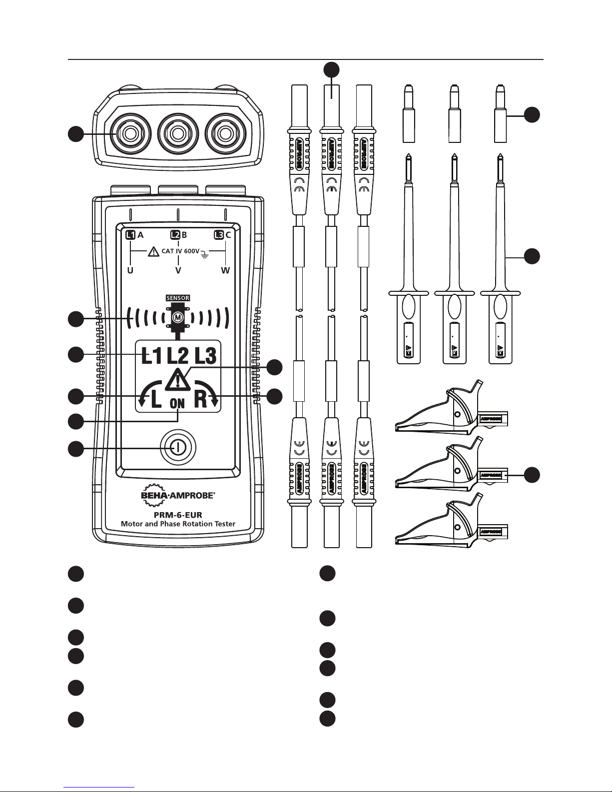
1Input terminals for L1 (A), L2 (B), L3 (C)
2Non-contact motor orientation
symbol and sensor indicator
3Symbol for L1, L2, L3 indicators
4Symbol for counter-clockwise
rotation
5Symbol for clockwise rotation
6“Warning symbol” for false input
voltage
PRM-6-EUR Motor and Phase Rotation Tester
7ON symbol for Non-Contact
Rotary Field Indication
and Determine the Motor
Connection
8ON button / Backlight
9Test leads (black, red, yellow)
10 Probe tip cap (black, red, yellow)
11 Test probe (black, red, yellow)
12 Alligator clips (black, red, yellow)
a6Axm
CAT II 1000V
CAT IV 600V
a6Axm
CAT II 1000V
CAT IV 600V
a6A
xm
CAT II 1000V
CAT IV 600V
61557-7 L1/A
61557-7 L2/B
61557-7 L3/C
4 5
8
7
1
3
2
6
10
11
12
9
3
SYMBOLS
Caution! Risk of electric shock.
WCaution! Refer to the explanation in this manual.
TThe equipment is protected by double insulation or reinforced
insulation
JEarth (Ground)
CAT IV
Measurement category IV (CAT IV) is for measurement
performed at the source of the low-voltage installation.
Examples are electricity meters and measurement on primary
overcurrent protection device and ripple control units.
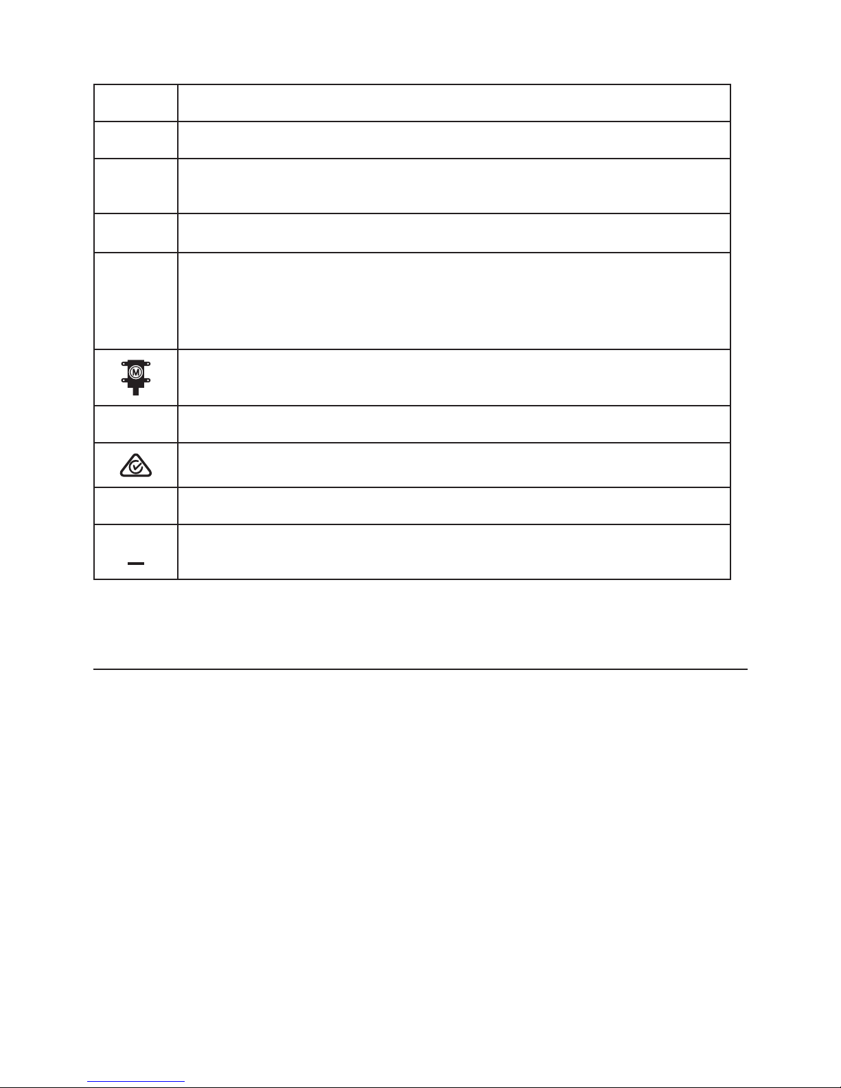
Orientation symbol for non-contact motor rotary field
indication.
PComplies with European Directives.
Conforms to relevant Australian standards
)Canadian Standards Association (NRTL/C).
=Do not dispose of this product as unsorted municipal waste.
Contact a qualified recycler.
SAFETY INFORMATION
The meter complies with:
IEC/EN 61557-1/-7
IEC/EN 61010-1 3rd Edition, UL61010-1 3rd Ed. and CAN/CSA C22.2 No. 61010-
1-12 to CAT IV 600 V, pollution degree 2
IEC/EN 61010-2-030
IEC/EN 61010-2-31 for test leads
EMC IEC/EN 61326-1
CENELEC Directives
The instruments conform to CENELEC low-voltage directive 2006/95/EC and
electromagnetic compatibility directive 2004/108/EC.

4
W
Warning
To prevent possible electrical shock, fire, or personal injury:
• Carefully read all instructions. Read safety information before using or
servicing the tester.
• Comply with local and national safety codes. Use personal protective
equipment (approved rubber gloves, face protection, and flame resistant
clothes) to prevent shock and arc blast injury where hazardous live
conductors are exposed.
• Use the product only as specified, or the protection supplied by the
product can be compromised.
• Do not work alone.
• Consider mechanical risks and risks of rotating mechanical parts. Comply
with local and national safety codes.
• Do not use the tester or test leads if they appear damaged. Examine the
tester and test leads for damaged insulation or exposed metal. Check
test lead continuity. Replace damaged test leads before using the tester.
• Do not touch voltages >30 V AC RMS, 42 V AC peak, or 60 V DC. These
voltages pose electrical shock hazards. Keep fingers behind the finger
guards on the probes and alligator clips.
• To avoid false readings, which could lead to possible electric shock or
personal injury, check the battery and verify operation beforehand on a
known source.
• Do not exceed the Measurement Category (CAT) rating of the lowest
rated individual component of a product, probe, or accessory.
• If the tester is used in a manner not specified in the users manual, the
protection provided by the equipment may be impaired.
• Measurements can be adversely affected by impedances of additional
operating circuits connected in parallel or by transient currents.
• Do not use the PRM-6-EUR with any of the parts removed.
• Disconnect the test leads from energized circuits and from the tester
before opening the battery cover.
• Do not use the product around explosive gas, vapor, or in damp or wet
environments.
• Have the tester serviced only by qualified service personnel.
• Only use the test lead sets provided with the tester. Alternative test
leads may not fulfill the requirements of EN 61557-7.

5
UNPACKING AND INSPECTION
Your shipping carton should include:
1 PRM-6-EUR Motor and Phase Rotation Tester
3 Test leads (black, red, yellow)
3 Test probes (black, red, yellow)
3 Alligator clips (black, red, yellow)
2 1.5V AAA battery (installed)
1 Users manual
1 Carrying case
If any of the items are damaged or missing, return the complete package to
the place of purchase for an exchange.
USING MOTOR AND PHASE ROTATION TESTER
Determine the Rotary Field Direction
To determine the rotary field direction:
1. Connect one end of test leads to the tester’s corresponding terminals L1,
L2, and L3.
2. Connect the alligator clips or the test probes to the other end of the test
leads.
3. Connect the alligator clips/test probes to the three mains phases.
4. L1, L2 and L3 indicators shows voltage is present.
5. The clockwise or counter-clockwise rotary indicator shows the type of
rotary field direction present.
6. If the “Warning Symbol” illuminates, either one or two of the inputs are
connected to the neutral conductor or the voltage difference between
the phases exceed 30% phase to phase or 65% between phase to
neutral.
Note:
• The PRM-6-EUR is powered by the motor or system being tested.
• In environment with poor light condition you can switch on the
Backlight while pressing and hold button “ON” to improve visibility.
W
Warning
The rotary indicator L1, L2 and L3 lights even if the neutral conductor, N, is
connected instead of L1, L2, or L3. Refer to Figure 1 for more information
about what appears on the back of the PRM-6-EUR).
6
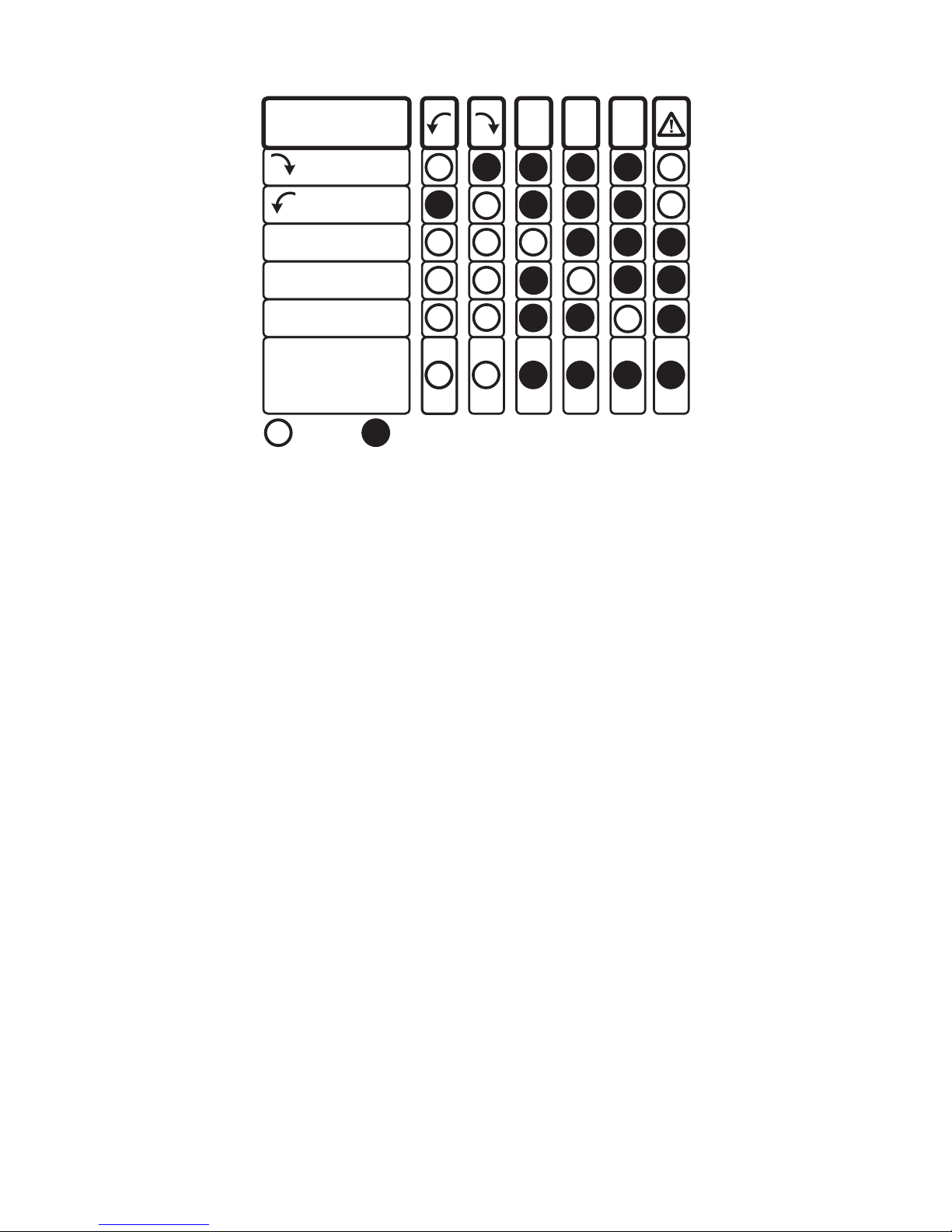
DISPLAY
L1 MISSING
L2 MISSING
L3 MISSING
L1
A
L2
B
L3
C
ONE INPUT
CONNECTED
TO N OR PE
OFF ON
CORRECT
FALSE
R
L
L R
Figure 1: Phase indication table
(also printed on the back of the PRM-6-EUR)
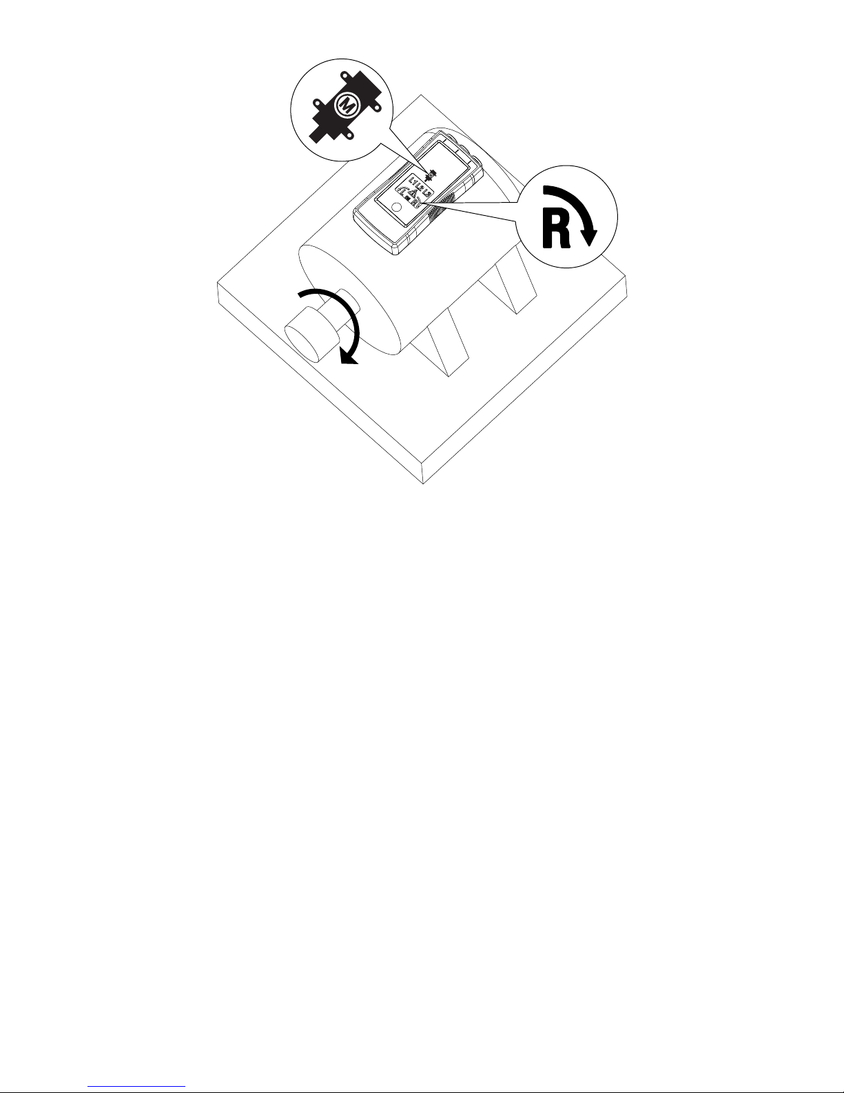
Non-Contact Rotary Field Indication
For non-contact rotary field indication:
1. Disconnect all test leads from the PRM-6-EUR for safety reason.
2. Position the PRM-6-EUR on the motor so it is parallel to the length of
the motor shaft. The sensor of the tester should be in the center of the
motor windings. The tester should be as close as possible to the motor.
See Figure 2.
3. Press and hold the ON button. The LC display shows “ON,” indicating the
PRM-6-EUR is ready for testing.
4. Either the clockwise or counter-clockwise rotary indicator will illuminate,
showing the type of rotary field direction present.
If the LC display don’t show the “ON” symbol, while pressing the ON button,
the battery does not have a charge and needs to be replaced.
WThe Indicator will not operate with motor controlled by frequency
converters. The bottom of the PRM-6-EUR should be oriented towards the
drive shaft. See the Orientation Symbol on the PRM-6-EUR.
If the motor was disconnected from electricity for a long time (typically one
year), the residual field / magnetization may be too weak for the tester to
measure the rotation.
7
Figure 2: Motor Rotation
Determine the Motor Connection
1. Connect one end of test leads to the tester’s corresponding terminals L1,
L2, and L3.
2. Connect the alligator clips or the test probes to the other end of the test
leads.
3. Connect the alligator clips or test probes to the motor connections, L1 to
U, L2 to V, L3 to W.
4. Press the ON button. The LC display shows “ON,” indicating the PRM-6-
EUR is ready for testing.
5. Turn the motor shaft towards the right.
6. Either the clockwise or counter-clockwise rotary indicator will illuminate,
showing the rotary field direction.
If the LC display don’t show the “ON” symbol, while pressing the ON button,
the battery does not have a charge and needs to be replaced.
Note: If you get a another indication of the rotary field direction as expected
then swap two connection from step 3 and repeat testing. Use the new order
of U (L1), V (L2) and W (L3) for further purpose
8
Backlight
The backlight is turned on while pressing and hold button “ON” and it is
powered by the battery.
If the backlight don’t illuminate the battery does not have a charge and
needs to be replaced.
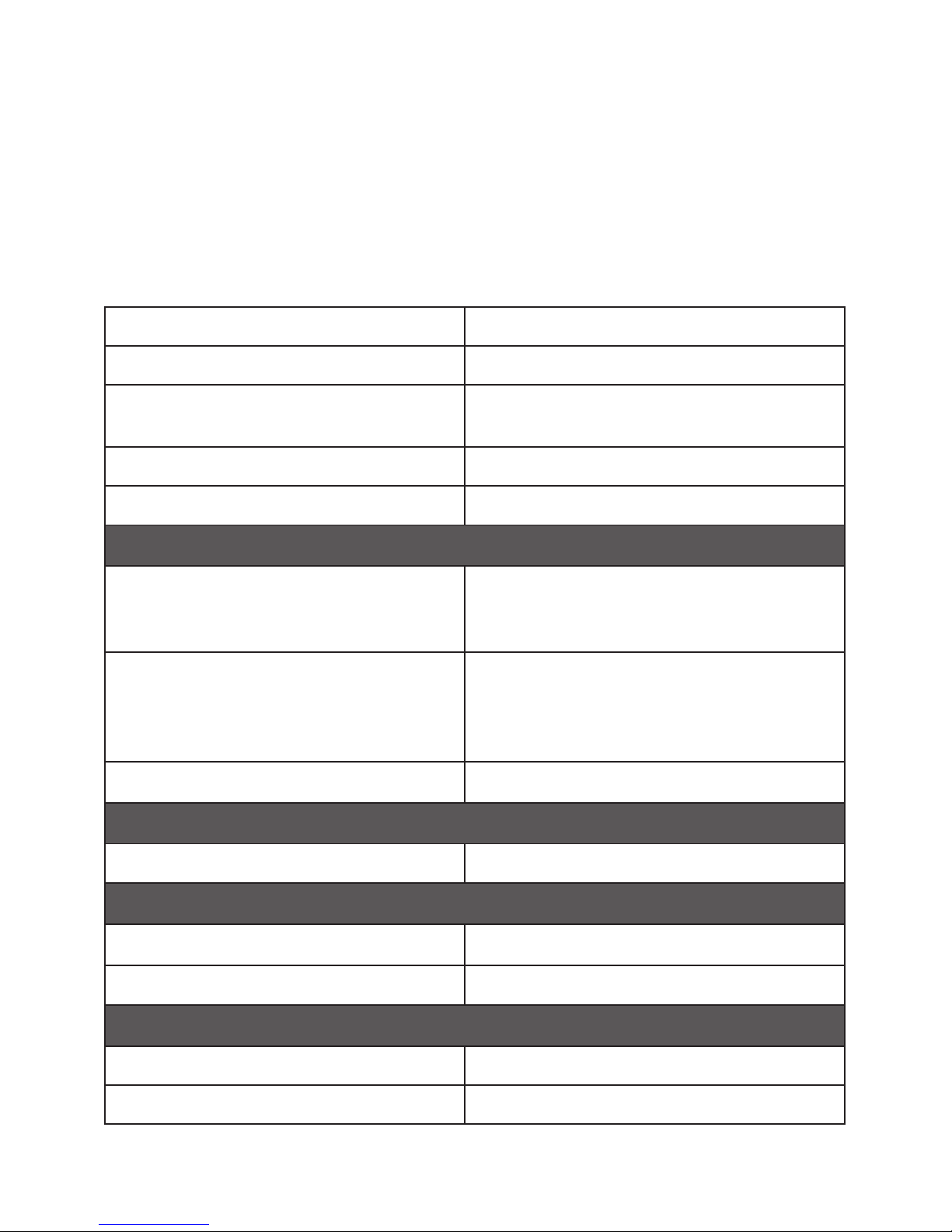
SPECIFICATIONS
3 phase indication Via LCD
Indication of phase rotation Via LCD
Indication of motor rotation direction
Non-contact rotary field indication Via LCD
Determine the motor connection Via LCD
LC display backlight Yes
Determine Rotary Field Direction
Frequency range (fn) /
Voltage range (Ume)
16...60 Hz / 40...700V AC phase to phase
>60...400 Hz / 50...700V AC phase to
phase
Indicaton for false input voltage difference of > ±30% between the
phase to phase voltages
(> ± 65% between phase to neutral
voltages)
Nominal test current (In in per phase) ≤3.5 mA
Non-Contact Rotary Field Indication
Frequency range (fn)16 to 400 Hz
Determine the Motor Connection
Voltage range (Ume) ≥1 V AC phase to phase
Frequency range (fn) 2 to 400 Hz
General Specifications
Operating time Continuous
Operating temperature 0OC to 40OC (32OF to 104OF)

9
Operating altitude Up to 2000 m
Humidity (Without condensation) ≤80% RH
Storage conditions 0OC to 40OC (32OF to 104OF), ≤80% RH
Power supply 2 x 1.5 V AAA alkaline battery
Battery life Minimum 2 years for average use
Dust/water resistance IP 40
Pollution degree 2
Dimensions (H x W x D) 137 x 65 x 33 mm (5.43 x 2.56 x 1.3 in)
Weight 170 g (0.38 lb) (battery installed)
Product Standard EN 61557 -1/-7
Electrical safety EN 61010-1, EN 61557-7
Overvoltage category CAT IV 600 V
EMC Conforms to EN 61326-1
Agency approvals ) P
MAINTENANCE
W
Caution
To prevent damage to the PRM-6-EUR:
• Do not attempt to repair or service the PRM-6-EUR unless qualified to
do so.
• Make sure that the relevant calibration, performance test, and service
information is being used.
• Do not use abrasives or solvents. Abrasives or solvents will damage the
PRM-6-EUR case.
Cleaning
The only maintenance the PRM-6-EUR requires is inspection and cleaning.
Periodically wipe the case with a mild solution of detergent and water. Apply
sparingly with a soft cloth and allow to dry completely before using. Do not
use aromatic hydrocarbons, gasoline or chlorinated solvents for cleaning.

10
Replacing and Disposing of the Battery
W
Warning
• To avoid electric shock, disconnect the test leads from the source before
opening the PRM-6-EUR for battery replacement.
• To avoid false readings, which could lead to possible electric shock or
personal injury, replace the battery as soon as the battery is low or
dead.
= Note: The PRM-6-EUR contains alkaline battery. Do not dispose of the
battery with other solid waste.
Used batteries should be disposed of by a qualified recycler or hazardous
materials handler. Contact your authorized Amprobe Service center for
recycling information.
The PRM-6-EUR uses two 1.5 V AAA batteries (supplied). To replace the
batteries, follow these steps and refer to Figure 3:
1. Disconnect test leads from any power source.
2. Place the PRM-6-EUR face down on a nonabrasive surface and loosen the
battery-door lock with a flat screwdriver.
3. Lift the battery cover away from the PRM-6-EUR.
4. Replace the batteries as shown in Figure 3. Observe the battery polarity
shown in the battery compartment.
5. Replace the battery cover to the lock position.
AAA
AAA
Figure 3: Replacing batteries

PRM-6-EUR
Motor- und Phasenfolgetester
Bedienungsanleitung
4/2015, Rev. A
© 2015 Beha-Amprobe.
Alle Rechte vorbehalten. In China gedruckt.
Deutsch

Eingeschränkte Garantie und Haftungseinschränkungen
Innerhalb eines Jahres ab Kaufdatum oder innerhalb des gesetzlich vorgeschriebenen
Mindestzeitraums garantieren wir, dass Ihr Amprobe-Produkt keinerlei Material- und
Herstellungsfehler aufweist. Sicherungen, Trockenbatterien sowie Schäden durch Unfall,
Fahrlässigkeit, Missbrauch, Manipulation, Kontamination sowie anomale Nutzung und
Einsatzbedingungen werden nicht durch die Garantie abgedeckt. Händler sind nicht berechtigt,
jegliche Erweiterungen der Garantie im Namen von Amprobe in Aussicht zu stellen. Um
Serviceleistungen während der Garantiezeit in Anspruch zu nehmen, übergeben Sie das Produkt
mitsamt Kaufbeleg einem autorisierten Amprobe-Servicecenter oder einem Amprobe-Händler
oder -Distributor. Details dazu finden Sie im Reparatur-Abschnitt. Sämtliche Ansprüche Ihrerseits
ergeben sich aus dieser Garantie. Sämtliche sonstigen Gewährleistungen oder Garantien, ob
ausdrücklich, implizit oder satzungsgemäß, sowie Gewährleistungen der Eignung für einen
bestimmten Zweck oder Handelstauglichkeit werden hiermit abgelehnt. Der Hersteller haftet
nicht für spezielle, indirekte, beiläufige oder Folgeschäden sowie für Verluste, die auf andere
Weise eintreten. In bestimmten Staaten oder Ländern sind Ausschlüsse oder Einschränkungen
impliziter Gewährleistungen, beiläufiger oder Folgeschäden nicht zulässig; daher müssen diese
Haftungseinschränkungen nicht zwingend auf Sie zutreffen.
Reparatur
Sämtliche innerhalb oder außerhalb der Garantiezeit zur Reparatur oder Kalibrierung
eingereichten Geräte sollten mit folgenden Angaben begleitet werden:Ihr Name, Name Ihres
Unternehmens, Anschrift, Telefonnummer und Kaufbeleg. Zusätzlich fügen Sie bitte eine
Kurzbeschreibung des Problems oder der gewünschten Dienstleistung bei, vergessen Sie auch
die Messleitungen des Gerätes nicht. Gebühren für Reparaturen oder Austausch außerhalb der
Garantiezeit sollten per Scheck, Überweisung, Kreditkarte (mit Angabe des Ablaufdatums) oder
per Auftrag zugunsten Amprobes beglichen werden.
Reparatur und Austausch innerhalb der Garantiezeit – Alle Länder
Bitte lesen Sie die Garantiebedingungen, prüfen Sie den Zustand der Batterie, bevor Sie
Reparaturleistungen in Anspruch nehmen. Innerhalb der Garantiezeit können sämtliche
defekten Prüfwerkzeuge zum Austausch gegen ein gleiches oder gleichartiges Produkt an Ihren
Amprobe-Distributor zurückgegeben werden. Eine Liste mit Distributoren in Ihrer Nähe finden
Sie im Bezugsquellen-Bereich bei www.Amprobe.com. In den USA und in Kanada können Geräte
zum Austausch oder zur Reparatur auch an das Amprobe-Servicecenter (Anschrift weiter unten)
eingesandt werden.
Reparatur und Austausch außerhalb der Garantiezeit – USA und Kanada
Außerhalb der Garantiezeit sollten Geräte in den USA und in Kanada zur Reparatur an
ein Amprobe-Servicecenter gesandt werden. Informationen zu aktuellen Reparatur- und
Austauschgebühren erhalten Sie von Ihrem Händler oder telefonisch von Amprobe.
USA: Kanada:
Amprobe Amprobe
Everett, WA 98203Mississauga, ON L4Z 1X9
Tel.: 877-AMPROBE (267-7623)Tel.: 905-890-7600
Reparatur und Austausch außerhalb der Garantiezeit – Europa
In Europa können Geräte außerhalb der Garantiezeit gegen eine geringe Gebühr von Ihrem
Amprobe-Distributor ausgetauscht werden. Eine Liste mit Distributoren in Ihrer Nähe finden
Sie im Bezugsquellen-Bereich bei www.Amprobe.eu.
Amprobe Europe*
Beha-Amprobe
In den Engematten 14
79286 Glottertal, Deutschland
Tel.: +49 (0) 7684 8009 - 0
www.Beha-Amprobe.com
(Nur Korrespondenz – weder Reparatur noch Austausch über diese Adresse. Europäische Kunden wenden
sich bitte an ihren Distributor.)

1
PRM-6-EUR – Motor- und Phasenfolgetester
INHALT
Symbole..............................................................................................................3
Sicherheitshinweise...........................................................................................3
Auspacken und prüfen ......................................................................................5
Motor- und Phasenfolgetester verwenden......................................................5
Drehfeldrichtung bestimmen .......................................................................5
Berührungslose Drehfeldanzeige.................................................................6
Motorverbindungsprüfung...........................................................................7
Hintergrundbeleuchtung..............................................................................9
Technische Daten ...............................................................................................8
Wartung..............................................................................................................9
Reinigung.......................................................................................................9
Batterie austauschen und entsorgen ...........................................................10
2
1Eingangsanschlüsse für L1 (A), L2
(B), L3 (C)
2Symbol für berührungslose
Motorprüfung und Sensoranzeige
3L1-, L2-, L3-Anzeigesymbole
4Symbol für Drehung gegen den
Uhrzeigersinn
5Symbol für Drehung im
Uhrzeigersinn
6Warnsymbol für falsche
Eingangsspannung
PRM-6-EUR – Motor- und Phasenfolgetester
7ON-Symbol zur berührungslosen
Drehfeldanzeige und
Motorverbindungsprüfung
8EIN-Taste/
Hintergrundbeleuchtung
9Messleitungen (schwarz, rot, gelb)
10 Messspitzenkappen (schwarz, rot,
gelb)
11 Messspitzen (schwarz, rot, gelb)
12 Krokodilklemmen (schwarz, rot,
gelb)
a6Axm
CAT II 1000V
CAT IV 600V
a6Axm
CAT II 1000V
CAT IV 600V
a6A
xm
CAT II 1000V
CAT IV 600V
61557-7 L1/A
61557-7 L2/B
61557-7 L3/C
4 5
8
7
1
3
2
6
10
11
12
9

3
SYMBOLE
Achtung! Stromschlaggefahr.
WAchtung! Erläuterung in dieser Anleitung beachten.
TDoppelte oder verstärkte Geräteisolierung.
JErde (Masse).
CAT IV
Die Messkategorie IV (CAT IV) gilt für Messungen an der
Quelle von Niederspannungsinstallationen. Beispielsweise:
Messungen an Zählern, Überstromschutzgeräten und
Rundsteuergeräten
Richtungssymbol zur berührungslosen
Motordrehrichtungsanzeige.
PErfüllt europäische Vorgaben.
Erfüllt zutreffende australische Vorgaben.
)Canadian Standards Association (NRTL/C).
=Gerät nicht mit dem regulären Hausmüll entsorgen.
Qualifiziertes Recyclingsunternehmen nutzen.
SICHERHEITSHINWEISE
Das Messgerät entspricht folgenden Vorgaben:
IEC/EN 61557-1/-7
IEC/EN 61010-1 3. Ausgabe, UL61010-1 3. Ausgabe und CAN/CSA C22.2 No.
61010-1-12 bis CAT IV 600 V, Verunreinigungsgrad 2
IEC/EN 61010-2-030
IEC/EN 61010-2-31 für Messleitungen
EMC IEC/EN 61326-1
CENELEC-Direktiven
Das Instrument erfüllt die Vorgaben der CENELEC-Niederspannungsdirektive
2006/95/EC und der Direktive zur elektromagnetischen Verträglichkeit
2004/108/EC.

4
W
Warnung
Damit es nicht zu Stromschlägen, Bränden und Verletzungen kommt:
• Lesen Sie die gesamte Dokumentation aufmerksam durch. Machen Sie
sich mit den Sicherheitshinweisen vertraut, bevor Sie das Gerät nutzen
oder warten.
• Halten Sie örtliche und landesweite Sicherheitsvorgaben ein.
Tragen Sie an sämtlichen Stellen, an denen Gefährdungen durch
offen liegende, stromführende Leiter bestehen, persönliche
Schutzausrüstung (zugelassene Gummihandschuhe, Gesichtsschutz und
flammenhemmende Kleidung) zum Schutz vor Stromschlägen sowie
Verletzungen durch Funkenüberschläge.
• Verwenden Sie das Gerät ausschließlich wie angegeben; andernfalls
können die Schutzeinrichtungen des Gerätes beeinträchtigt werden.
• Arbeiten Sie nicht allein.
• Beachten Sie mechanische Gefährdungen und Gefährdungen
durch rotierende Teile. Halten Sie örtliche und landesweite
Sicherheitsvorgaben ein.
• Verwenden Sie weder Gerät noch Messleitungen, falls Beschädigungen
vorliegen oder vorliegen könnten. Untersuchen Sie Gerät und
Messleitungen auf beschädigte Isolierungen und freiliegende
Metallteile. Prüfen Sie die Messleitungen auf Durchgang. Wechseln Sie
beschädigte Messleitungen aus, bevor Sie das Gerät benutzen.
• Berühren Sie keine Spannungen über 30 V Wechselspannung (RMS),
42 V Wechselspannung (Spitze), 60 V Gleichspannung. Bei solchen
Spannungen besteht Stromschlaggefahr. Fassen Sie Messspitzen und
Krokodilklemmen ausschließlich hinter dem Fingerschutz an.
• Damit es nicht zu falschen Messungen kommt, die möglicherweise
zu Stromschlägen und Verletzungen führen können, überprüfen Sie
die Batterie sowie die einwandfreie Funktion des Gerätes mit einer
bekannten Quelle.
• Überschreiten Sie niemals die Messkategorieeinstufung (CAT) der jeweils
geringst eingestuften Einzelkomponente eines Gerätes, Messfühlers
oder Zubehörteils.
• Falls das Gerät auf eine nicht in dieser Anleitung beschriebene
Weise eingesetzt wird, können die Schutzeinrichtungen des Gerätes
beeinträchtigt werden.
• Messungen können durch Impedanzen zusätzlicher, parallel geschalteter
Schaltkreise oder durch transiente Ströme beeinträchtigt werden.
• Nutzen Sie den PRM-6-EUR niemals in unvollständigem Zustand.
• Trennen Sie die Messleitungen von spannungsführenden Schaltungen
und vom Tester, bevor Sie das Batteriefach öffnen.
• Verwenden Sie das Gerät nicht in der Nähe von explosiven Gasen,
Dämpfen und nicht an feuchten oder nassen Stellen.
• Lassen Sie das Gerät ausschließlich von qualifizierten Fachleuten warten.
• Verwenden Sie ausschließlich die mit dem Tester gelieferten
Messleitungen. Andere Messleitungen entsprechen eventuell nicht den
Vorgaben gemäß EN 61557-7.
Table of contents
Languages:
Other Beha-Amprobe Measuring Instrument manuals

Beha-Amprobe
Beha-Amprobe Telaris Series User manual

Beha-Amprobe
Beha-Amprobe DR 705 User manual

Beha-Amprobe
Beha-Amprobe AC50A User manual

Beha-Amprobe
Beha-Amprobe UAT-600-EUR Series User manual

Beha-Amprobe
Beha-Amprobe AT-7000-EUR User manual

Beha-Amprobe
Beha-Amprobe 4930890 User manual

Beha-Amprobe
Beha-Amprobe PRM-5-EUR User manual
Popular Measuring Instrument manuals by other brands

ISOMAG
ISOMAG CS3820 Operating and maintenance manual

YOKOGAWA
YOKOGAWA Power Series Plus IM 2493WVP-1 user manual

Lutron Electronics
Lutron Electronics MHT-381SD Operation manual

Hanna Instruments
Hanna Instruments HI 99161 instruction manual

YOKOGAWA
YOKOGAWA PX8000 user manual

intellic
intellic EFAS-4.8 user guide


