Promega Maxwell 16 MDx User manual

INSTRUCTIONS FOR
USE OF PRODUCT
AS3000-SC
AS3000-LC
Maxwell®16 MDx Instrument
Technical Manual
PRINTED IN USA. 9/09 Part# TM320

1. Introduction 1
A. Maxwell®16 MDx Purification Procedure 1
B. Maxwell®16 MDx Instrument Specifications 1
C. Product Components 1
D. Inspection 2
E. Precautions 3
F. Environmental Requirements (operating, shipping and
storage conditions) 3
2. Hardware Overview 4
3. Hardware Mode 6
4. Unpacking and Setting Up the Maxwell®16 MDx
Instrument 6
A. Unpacking 6
B. Removing the Magnetic Rod Assembly/Plunger Bar
Platform Shipping Anchors 6
C. UV Bulb Installation 7
D. Maxwell®Sample Track 7
E. Operational Setup 7
5. Operating the Maxwell®16 MDx Instrument 11
A. Preprogrammed Methods 11
B. Setting Up Samples and Collecting Input Data 12
C. Performing a Sample Purification Run 15
D. Post-Run UV Light Treatment 16
6. Run Reports 16
A. Data File Transfer at the End of a Run 16
B. Data File Transfer at a Later Time 16
C. Data File Management 17
7. Changing Configuration Parameters 17
A. Changing the Hardware 17
B. Changing the Instrument Firmware Configuration 19
8. Cleaning and Maintenance 19
A. General Care 19
B. Cleaning the Hardware 20
C. Dealing with Spills 20
D. Decontamination Using the UV Lamp 20
E. Replacing the UV Bulb 20
F. Periodic Maintenance 20
9. Troubleshooting 21
10. Appendix 24
A. User-Defined Methods 24
B. Homogenization Method 27
C. Updating Firmware 28
D. Service 29
E. Instrument Return 29
F. Instrument Disposal 30
11. Warranties, Service Agreements and Related
Products 30
A. Warranty Information 30
B. Warranty and Service Agreement Options 31
C. Related Products 31
12. Certificate of Decontamination 32
Promega Corporation
2800 Woods Hollow Road • Madison, WI 53711-5399 USA part# TM320
Toll Free in USA 800-356-9526 • Phone 608-274-4330 rev. 9/09
Maxwell®16 MDx Instrument Technical Manual

1. Introduction
A. Maxwell®16 MDx Purification Procedure
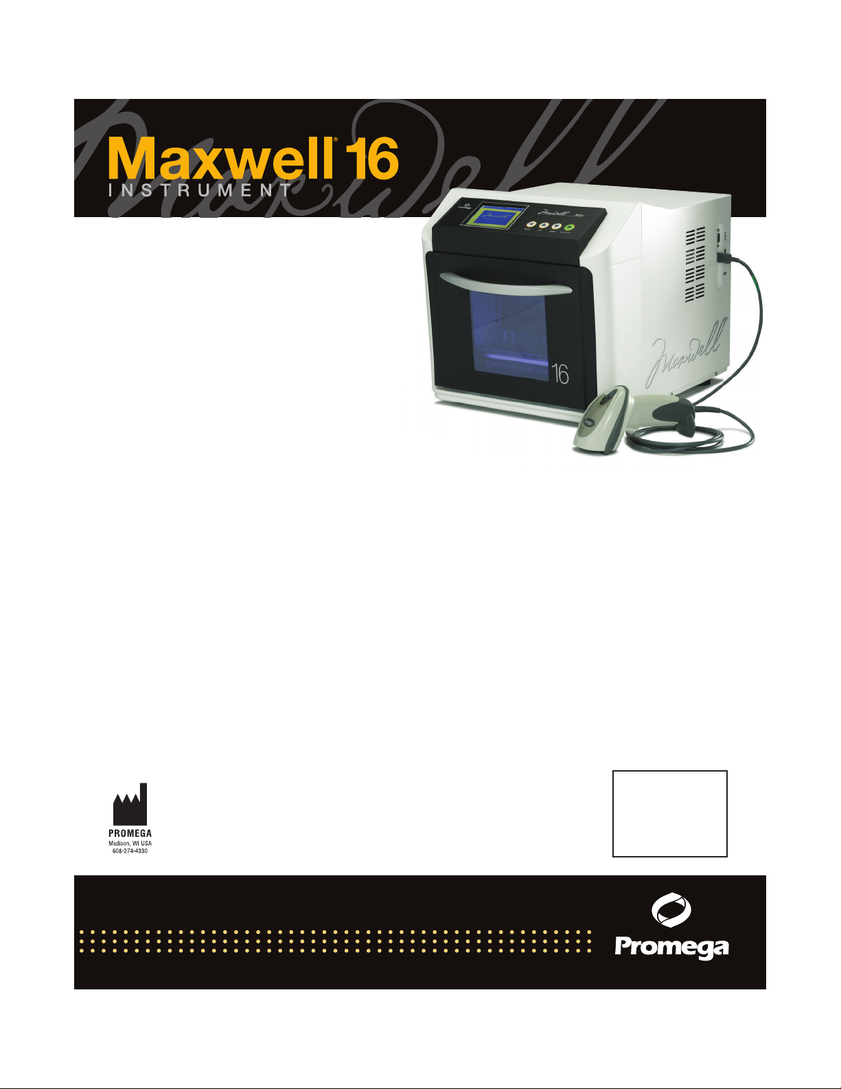
The Maxwell®16 MDx Instrument(a) provides automated
nucleic acid purification methods for multiple analytes.
The methods use sample lysis and binding to paramagnetic
particles as the primary separation principle. It has two
modes for different elution volumes. The Standard Elution
Volume (SEV) mode allows elution in a volume of up to
400μl. The Low Elution Volume (LEV) mode allows elution
in as little as 25μl. Up to 16 samples can be prepared in a
single run.
The automated steps performed by the Maxwell®16 MDx
Instrument include:
• Sample lysis in the presence of a chaotropic agent,
detergent and/or alcohol
• Binding of nucleic acids or proteins to paramagnetic
particles
• Washing of the target molecules bound to the particles
away from other cellular components
• Elution of the product
The instrument contains a touch screen for navigating,
programming and running the instrument. It has a UV
lamp to aid with decontamination. The Maxwell®16 MDx
Instrument, in association with the Maxwell®Sample Track
software, has the ability to record and provide run data. It
has a USB port that can be used to attach a bar code reader
allowing sample and reagent information to be entered
using bar codes. The Maxwell®16 MDx Instrument can
report the data gathered for each run, and the report can
be sent to a serial printer or to a computer.
The user selects the protocol to be run, collects the selected
bar code information (optional) and places the samples into
the reagent cartridges. The cartridges are placed into the
machine and the door shut to start the run, which
automatically performs the protocol.
The temperature of the samples is regulated by a heating
system that is controlled by the protocol.
Maxwell®Sample Track is a communications program that
allows downloading and printing of the run data (see
Technical Manual #TM314).
Maxwell®16 MDx Instrument Features
• Easy-to-use and easy-to-maintain system operation that
standardizes nucleic acid or protein sample preparation
workflow
• Comprehensive technical support
• System controlled via multi-language LCD readout
• UV lamp to aid in decontamination of instrument
• Reporting functionality
•Maxwell®Sample Track Software and bar code reader
included
• Preprogrammed methods for DNA, RNA and protein
purification
• Ability to create user-defined protocols
B. Maxwell®16 MDx Instrument Specifications
Processing Time: Depending upon sample type and method
used, 20–50 minutes
Number of Samples: up to 16
Weight: 42.7lb (19.4kg)
Dimensions (W × D × H): 12.8 × 17.3 × 12.9 inches (325.5 ×
438.2 × 326.5mm)
Power Requirements: 100–240VAC, 50–60Hz, 2.1A
Fuse: 3A time-lag fuse
UV Bulb: Average lifetime approx. 3000 hours, length
134.5mm, diameter 15.5mm, 4.5W, 0.17A current, 29V,
Spectral Peak 253.7, UV output 0.8W
C. Product Components
General Purpose Laboratory Equipment
AS3000 Maxwell®MDx Instruments include:
•1 Maxwell®16 MDx Instrument
• 1 power cable
• 1 UV lamp bulb*
• 1 SD card
• 1 SD card reader package (contains SD card reader and
cable)
• 1 CD containing the technical manual
• 1 Quick Start Guide
• 1 Bar Code Reader (provided in a separate box)
• 1 CD Containing Sample Track Software and manual
• 1 RS-232 Cable for communication with a computer or
printer
• 1 RS-232/USB Adaptor for data export to computer
* The UV bulb contains mercury and must be disposed of
properly. To dispose of a bulb, please follow your
institutional requirements for cleanup and disposal of
mercury.
Cat.# AS3000-SC (SEV Configuration**) includes:
• 1 cartridge rack
• 1 magnetic elution rack
Cat.# AS3000-LC (LEV Configuration**) includes:
• 1 LEV cartridge rack
**The rack(s) provided depends on the hardware mode
options that have been purchased. If both the SEV and LEV
hardware are ordered, the instrument will be provided
configured in the LEV mode with the SEV hardware
supplied separately.
Promega Corporation
2800 Woods Hollow Road • Madison, WI 53711-5399 USA part# TM320
Toll Free in USA 800-356-9526 • Phone 608-274-4330 rev. 9/09
Maxwell®16 MDx Instrument Technical Manual
1

Table 1. Symbol Key.
ExplanationSymbol
Important
!
Manufacturer
Catalog Number
Serial Number
SN
D. Inspection
Upon receiving your Maxwell®16 MDx Instrument, please
inspect the package carefully to make sure all accessories
are present and that the instrument has not been damaged
in shipping. If any item is damaged, contact Promega
Technical Services. Standard accessories are shown in
Figures 1 and 2.
Figure 1. Maxwell®16 MDx SEV Components with Sample
Tracking Components shown include: bar code reader cable, bar
code reader, cartridge rack, elution rack, power cord, UV bulb, SD
card reader and cable, SD card, RS-232/USB adaptor cable, RS-232
cable. Not pictured: Quick Start Guide, CD containing Technical
Manual and CD containing Sample Track Software. Bar code reader
and bar code reader cable are provided in a separate box.
Figure 2. Maxwell®16 MDx Instrument LEV Components with
Sample Tracking Components shown include: bar code reader
cable, bar code reader, cartridge rack, power cord, UV bulb, SD
card reader and cable, SD card, RS-232/USB adaptor cable, RS-232
cable. Not pictured: Quick Start Guide, CD containing Technical
Manual and CD containing Sample Track Software. Bar code reader
and bar code reader cable are provided in a separate box.
Promega Corporation
2800 Woods Hollow Road • Madison, WI 53711-5399 USA part# TM320
Toll Free in USA 800-356-9526 • Phone 608-274-4330 rev. 9/09
Maxwell®16 MDx Instrument Technical Manual
2

E. Precautions
Important Safety Instructions. Save these instructions.
Table 2. Safety Symbols and Markings.
ExplanationSymbol
Danger. Hazardous voltage.
Risk of electrical shock.
Warning. Risk of personal
injury to the operator or a
safety hazard to the
instrument or surrounding
area.
Warning. Pinch point hazard.
Warning. Hot surface. Burn
hazard.
Warning. Lifting hazard.
Warning. Biohazard.
Warning. UV light hazard. Do
not look directly at the UV
light.
Warning. Wear Gloves When
Handling.
8252MA
Warning. It is important to
understand and follow all
laws regarding the safe and
proper disposal of electrical
instrumentation and
components. Please contact
your local Promega
Representative for disposal of
the instrument. Please follow
your institutional
requirements for disposal of
the accessories.
• Changes or modifications to this unit not expressly
approved by the party responsible for compliance could
void the user’s authority to operate the equipment.
• This equipment has been designed and tested to CISPR
11 Class A. In a domestic environment it may cause
radio interference, in which case you may need to take
measures to mitigate the interference.
• Do not use this device in proximity to sources of strong
electromagnetic radiation (e.g., unshielded intentional
RF sources), as these may interfere with the proper
operation.
• Do not use this instrument for anything other than its
intended use.
• Always disconnect the power before cleaning or
performing routine maintenance.
• Do not disassemble unit.
• Do not override the door sensor. Moving parts or
potential exposure to UV light from the bulb may cause
personal injury.
• Ensure cartridges, elution tubes and plungers have been
securely inserted in their correct positions and
orientation. Failure to do so may result in damage to
the instrument.
• After each run, verify that the plungers have been
completely removed from the magnet rods before
pressing Run/Stop to extend the platform.
•Use only Promega Maxwell®16 cartridges and plungers
designed for use with the appropriate hardware
configuration of the instrument.
• Do not reuse cartridges, plungers or elution tubes.
• UV bulb. Wear gloves when handling the bulb, for
example during insertion and removal of the bulb. Do
not operate the UV lamp if the instrument door is open.
• Use only Promega supplied UV bulbs (Cat.# SP1080).
• If the equipment is used in a manner other than that
specified by Promega, the protection provided by the
equipment may be impaired.
• Keep hands clear of instrument platform as it moves
in and out of the instrument.
• During elution, the heated elution block at the front of
the platform becomes very hot. Do not touch.
• To avoid muscle strain or back injury, use lifting aids
and proper lifting techniques when removing or
replacing the instrument. The Maxwell®16 MDx
Instrument weighs 42.7lb (19.4kg) and should be
handled by two people.
• Equipment can be hazardous due to the use of chemical
and biohazardous substances.
F. Environmental Requirements (operating, shipping and storage
conditions)
Power Requirements: 100–240VAC, 50–60Hz, 2.1A
Temperature: 5–40°C
Humidity: up to 80% relative humidity (for operation,
shipping and storage)
The Maxwell®16 MDx Instrument is intended for indoor
use only. Wipe up spills immediately. Install the instrument
on a clean, level surface. To avoid shortening the expected
lifespan of the instrument, install in a location that meets
the following criteria:
• Locate on a sturdy, level surface.
Promega Corporation
2800 Woods Hollow Road • Madison, WI 53711-5399 USA part# TM320
Toll Free in USA 800-356-9526 • Phone 608-274-4330 rev. 9/09
Maxwell®16 MDx Instrument Technical Manual
3

• Avoid dusty areas.
• Choose a location that has good air circulation and is
not exposed to direct sunlight.
• Avoid noisy electrical power sources (e.g., power
generators).
• Do not install in a location where there is large
temperature variability or high humidity.
• Position the instrument so that it is easy to unplug from
the power source.
• Do not place next to heat sources.
• Do not use near flammable gases or liquids.
• Do not place near other electrically sensitive
instruments.
2. Hardware Overview
Figures 3 and 4 show the front of the Maxwell®16 MDx
instrument.
Figure 3. Front of Maxwell®16 MDx Instrument.
Figure 4. Touch Screen and Keypad. The touch screen and the
keypad for use in navigating through the various screen displays
for the Maxwell®16 MDx Instrument. The same button selections
are available on the keypad and the screen. Both sets of buttons
can be used to navigate within and between screens. The Back and
Run/Stop buttons allow navigation between screens. The Up and
Down buttons are for navigation within a screen.
Figure 5. Power On/Off switch on the rear of the Maxwell®16
MDx Instrument. The rear of the instrument showing the On/Off
switch and where to connect the power cable. A 3 amp time-lag
fuse is located next to the power switch.
8082TB
On/o switch
Power cord
receptacle
RS-232 port
USB in port
SD card slot
Figure 6. Communications ports on the side of the instrument.
This side view shows the communication ports for the instrument.
The USB port is used to attach the bar code reader.
Promega Corporation
2800 Woods Hollow Road • Madison, WI 53711-5399 USA part# TM320
Toll Free in USA 800-356-9526 • Phone 608-274-4330 rev. 9/09
Maxwell®16 MDx Instrument Technical Manual
4

The RS-232 serial port can be used to connect to a computer
or a serial printer using the supplied RS-232 cable. If your
computer does not have an RS-232 port, a Tripp Lite®
connector is included and can be used to connect the
Maxwell®16 MDx Instrument via a USB port on the
computer using the adaptor attached to the RS-232 cable.
The USB connector port is for a bar code reader and only
allows bar code data to be imported into the Maxwell®16
MDx Instrument. Connect the USB plug from the bar code
reader to the instrument using this port. Data cannot be
exported from this connector port.
Note: Do not link a computer or printer to the USB port.
The SD Card slot is used to update firmware. An SD Card
is supplied with the Maxwell®16 MDx Instrument. This
card can be used to transfer firmware to the Maxwell®16
MDx Instrument from a computer (see Section 10.C). The
SD card slot cannot be used to download data from the
Maxwell®16 MDx Instrument. We recommend that you
keep the SD Card in the instrument to avoid misplacing it.
Linear slides
Linear slides
Standard magnetic rods
Plunger bar
LEV magnetic rods
Plunger bar
Magnetic rod
assembly
C. Maxwell
®
16 Platform
Heated elution
tube slots
Reagent
cartridge slots
5182TD
A. Standard Elution Volume (SEV) Configuration
B. Low Elution Volume (LEV) Configuration
LEV plunger bar
adaptor
Figure 7. Magnetic assembly components and platform.
Figure 7 shows the hardware components inside the
machine. The magnetic rod assembly varies depending on
the configuration (SEV or LEV). Figure 7, Panel A, shows
the SEV hardware configuration indicating the slides, which
allow the plunger to move up and down; the magnetic rod
assembly, which holds the magnets in place; and the
plunger bar, which contains the magnetic rods. Figure 7,
Panel B, shows the LEV hardware configuration that
incorporates an adaptor to hold the LEV magnetic rods and
LEV plunger bar. Figure 7, Panel C, shows the platform
indicating the slots where the SEV cartridges and elution
tubes are placed. For LEV, the cartridge sample rack
containing the LEV cartridges is placed on the platform
(rack not shown).
Promega Corporation
2800 Woods Hollow Road • Madison, WI 53711-5399 USA part# TM320
Toll Free in USA 800-356-9526 • Phone 608-274-4330 rev. 9/09
Maxwell®16 MDx Instrument Technical Manual
5

6391TA
Orientation of the Magnetic Rod Assembly
front
back
Figure 8. Orientation of Magnetic Rod Assembly. The orientation
of the magnetic rod assembly, with the screw holes facing the back
of the instrument.
Figure 8 shows the correct orientation of the magnetic rod
assembly. The screw holes face the back, and the magnetic
rods sit toward the front of the instrument. If the rod
assembly needs to be removed for cleaning (see Section 8)
and replaced, ensure that this orientation is retained.
3. Hardware Mode
The hardware mode chosen for each run depends on the
purification protocol being used. Please refer to the
Technical Bulletin or Manual for the various Maxwell®
Purification Kits for information on the hardware mode
setting required.
The existing hardware mode (SEV or LEV) setting is
displayed in the upper right hand corner of the Home
screen. The instrument displays the hardware mode entered
but does not sense the hardware installed. Always verify
that the hardware installed matches what is displayed on
the Home screen. Make sure that the hardware and
hardware mode are appropriate for the purification kit
being used. If the installed hardware is not correct for the
kit being used, remove the installed magnetic rod assembly
and replace it with the appropriate magnetic rod assembly
(see Section 7.A).
If the installed hardware does not match the hardware
mode displayed, turn the machine off, and install the
appropriate hardware with the machine turned off. When
the machine is powered up after the installation, the
installed hardware will match the hardware mode
displayed on the Home screen.
4. Unpacking and Setting Up the Maxwell®16 MDx
Instrument
A. Unpacking
1. Remove the accessory box, power cord and literature
package from the shipping container. Slide the
instrument out of the box. Note: Do not lift the
instrument out of the box by the door handle.
2. Remove the foam packaging from the sides of the
instrument, and remove the clear plastic cover.
3. Check that all the parts have been included (Figure 1
or 2).
4. Set the Maxwell®16 MDx Instrument on a flat, level,
solid surface in a dust-free location with good air
circulation. If possible, move the instrument back from
the edge of the surface to prevent inadvertently
bumping the open door.
!Important. Save the packaging material in case the
instrument needs to be returned for service or repair
later.
B. Removing the Magnetic Rod Assembly/Plunger Bar Platform
Shipping Anchors
1. Ensure that the instrument is turned off and unplugged.
2. The magnetic rod assembly, plunger bar and platform
are anchored in place during shipment to prevent
movement of and damage to these parts.
Note: If the instrument has been switched on before
removing the shipping anchors, you will hear the
motors grinding as they attempt to perform instrument
calibration. If this occurs, immediately turn off and
unplug the instrument and remove the shipping
anchors. This will not result in permanent damage to
the instrument.
3. Open the instrument door and locate the Magnetic Rod
Assembly/Plunger Bar and Platform Shipping Anchor
thumbscrews. (Figures 9 and 10). Remove them.
!Important. Save the shipping anchor thumbscrews in
case the instrument needs to be moved or returned for
service or repair at a later date.
Upper shipping anchors
6922TA
Figure 9. Upper shipping anchors.
Promega Corporation
2800 Woods Hollow Road • Madison, WI 53711-5399 USA part# TM320
Toll Free in USA 800-356-9526 • Phone 608-274-4330 rev. 9/09
Maxwell®16 MDx Instrument Technical Manual
6

Figure 10. Platform shipping anchors.
C. UV Bulb Installation
To prevent damage to the UV bulb, wear gloves—do not
touch the bulb with bare hands. Oil from your hands can
compromise the bulb and shorten its life span. Remove the
UV bulb from the box and wrapping. The bulb may rattle
if shaken; this is normal. Locate the UV lamp socket, which
is on the ceiling of the instrument just inside the door. Slide
the bulb into the socket (see Figure 11). Twist the bulb a
quarter turn until it is firmly in place. The UV bulb has an
average life of 3000 hours. The Maxwell®16 MDx
Instrument will warn you when the accumulated UV bulb
usage reaches 2950 hours, and we recommend that you
replace the bulb at that point. Replacement bulbs can be
purchased from Promega (Cat.# SP1080).
Figure 11. UV bulb in the power supply.
To replace the bulb, locate the old bulb in the UV lamp
holder, which is on the ceiling of the instrument just inside
the door (see Figure 11). Wear gloves—do not touch the
bulb with your bare hands. Twist the bulb a quarter turn
until it can slide out. Place the new bulb into UV lamp
socket and twist a quarter turn until it is firmly in place.
Your Maxwell®16 MDx Instrument is now ready for
operation.
D. Maxwell®Sample Track
To use the Maxwell®Sample Track software, you need to
load the software onto a computer that will be connected
to the Maxwell®16 MDx Instrument. See the Technical
Manual supplied with the software for more information.
To install the software, place the CD containing the
Maxwell®Sample Track software in the CD drive of your
computer, and follow the on-screen instructions.
During installation the Maxwell®Sample Track program
will check to see if Microsoft®Windows®Installer Version
3.1 and Microsoft®.NET Framework Version 2.0 are
installed on your computer. If necessary, the Maxwell®
Sample Track installer will prompt you to install these
applications, which are supplied on the Maxwell®Sample
Track CD. Once the software is loaded, connect the
computer to the RS-232 port of the Maxwell®16 MDx
Instrument using the RS-232 cable. Do not connect your
computer to the USB port on the Maxwell®16 MDx
Instrument. If your computer does not have a serial port,
use the supplied Tripp Lite®adaptor to connect the USB
port of the computer to the RS-232 cable. To use the Tripp
Lite®adaptor, you must first load the driver from the
minidisk in the Tripp Lite®box. Place the minidisk in the
CD drive of your computer and follow the instructions
supplied in the Tripp Lite®instruction manual.
Connect the bar code reader to the USB port on the side of
the instrument.
Users who wish to print run data directly can connect a
serial printer to the RS-232 port of the Maxwell®16 MDx
Instrument and print (see Section 6).
E. Operational Setup
Using the Touch Screen
Note: In the instructions below, screen names are presented
in bold type, and on-screen options are presented in italics.
The Maxwell®16 MDx touch screen allows the user to select
options. Most screens contain a series of navigation buttons
that allow the user to scroll up and down easily between
options. The touch screen buttons are the same as those on
the keypad (see Figure 4), and they perform the same
functions. Selection may be made using either set of
buttons. The Run/Stop button is located on the bottom right
of the touch screen.
Switching on the Instrument
Once the shipping anchors and all the packaging materials
have been removed, the UV bulb installed and the
peripherals attached, you can connect the instrument to a
power outlet. Ensure that the On/Off switch is in the off
position. The power switch is located next to the power
cord connection on the back of the instrument. Connect the
power cord to the back of the Maxwell®16 MDx
Instrument, and plug the power cord into a wall outlet. See
Section 1.F for power requirements. Switch instrument on
using the On/Off switch.
Every time the instrument is powered on, it will perform
a self-diagnostic test before opening the Home screen. The
platform, plunger bar and magnetic rod assembly are
moved to check operation, and the UV light is briefly
switched on to ensure that the bulb is functioning.
Promega Corporation
2800 Woods Hollow Road • Madison, WI 53711-5399 USA part# TM320
Toll Free in USA 800-356-9526 • Phone 608-274-4330 rev. 9/09
Maxwell®16 MDx Instrument Technical Manual
7

Shut down procedure: Switch the instrument "off" using
the On/Off switch. Unplug the machine. If you need to store
the instrument, switch the instrument "off", unplug the
instrument and store in a place that meets the
environmental requirements described in Section 1.F.
Configuring the Instrument Using the Maxwell®Wizard
The Maxwell®Wizard starts the first time the instrument
is switched on and guides you through the initial setup.
This Wizard will help you to set up the instrument
configuration to best meet your needs. During setup you
can set the following parameters: Language, Touch Screen
settings, Date/Time, UV Lamp run options, Sample
Tracking, Instrument Name and Approved Users. Settings
can be changed later if required (see Section 7.B).
The Wizard runs through the following option screens.
You can select the appropriate option as needed.
1. Language. The default language is English. If you wish
to change the language, choose from the list in the
Select Languages screen. You may need to scroll down
to the desired language. Once you have selected a
language, press the Run/Stop button.
8285TA
Figure 12. The Select Languages screen. Once you have
selected a language, press the forward arrow button
2. Touch Screen. You will need to calibrate the Touch
Screen after shipping.
8205TA
Figure 13. Calibrating the Touch Screen. To calibrate the
screen touch the "+" symbols in the order they are presented.
A confirmation screen will open.
8206TA
Figure 14. Confirmation screen for the Touch screen. Touch
all four boxes; if they all change color, press the Stop/Run
button on the instrument keypad. If they do not all change
color, press the back arrow button and repeat the calibration
and confirmation.
The "Touch Screen Reset Successful" message indicates
that the calibration was successful, and the Wizard can
continue.
3. Date/Time. Select the Date/Time screen to set the
current date and time. In the initial screens, select the
date and time formats. In the final Date/Time Setup
screen, set the current time and date. Selecting each of
the screen options opens a keypad to add numerical
values.
Promega Corporation
2800 Woods Hollow Road • Madison, WI 53711-5399 USA part# TM320
Toll Free in USA 800-356-9526 • Phone 608-274-4330 rev. 9/09
Maxwell®16 MDx Instrument Technical Manual
8

8207TA
Figure 15. Date/Time Setup screen.
4. UV Lamp. You can program the Maxwell®16 MDx
Instrument to turn on the UV lamp automatically. It
can be set to turn on after each run or at start up, or it
can be set to remain off.
The treatment time can be set in increments of 10
minutes for up to 10 hours. The UV lamp also can be
turned on from the Setup menu (see Section 8.D).
8208TA
Figure 16. UV Settings screen. Select the desired option on
the UV screen, and then set the time for UV treatment.
5. Sample Tracking In the Sample Tracking screen, you
can choose whether or not to collect tracking
information. If you choose "Tracking Options-on", you
will be able to choose the run report parameters to track
in the Barcode Options screen.
8209TA
Figure 17. Barcode Options screen. Select the options to be
reported.
!Important. The options chosen must be entered during
the run setup. Options not chosen will be displayed on
the Barcode Input screen during run setup (Section 5.B),
but you will not be able to scan bar code data for these
options.
6. Name Maxwell®16 MDx Instrument. This option
allows the user to assign a unique identifier to the
Maxwell®16 MDx Instrument that can be used to
identify the instrument on reports.
8210TA
Figure 18. Unit Name screen. Touching the screen to name
an instrument will open a keyboard to add a unique identifier.
7. User and PIN Setup. This option is a security tool for
adding approved users and associated Personal
Identification Numbers (PIN). This will require users
to add a PIN when they use the instrument. If you
choose "Yes", the Select Users screen opens. The screen
is initially populated with numbers. Select a number
and then press the Run/Stop button.
Promega Corporation
2800 Woods Hollow Road • Madison, WI 53711-5399 USA part# TM320
Toll Free in USA 800-356-9526 • Phone 608-274-4330 rev. 9/09
Maxwell®16 MDx Instrument Technical Manual
9

8211TA
Figure 19. User Settings screen.
In the User Settings screen, select Edit/Add User, press
the Run/Stop button, and add the user name using the
keyboard.
Note: The user name is limited to 15 characters.
Once the user name has been added, press the Run/Stop
button.
The Wizard will return to the User Settings screen. A
PIN can be added for each user for security. PIN
protection requires the user to enter a PIN to perform
a purification run. The PIN is four digits. The list of
users and associated PINs can be modified as described
in Section 7.B. Keep a separate list of all users and
associated PINs in case a PIN is forgotten.
An administrative password is included in the Welcome
Letter, sent with the instrument, which is used to access
all PIN-protected options. If you lose your
Adminstrative PIN, contact Promega Technical Services.
To add a PIN, select Edit/Add PIN in the User Settings
screen. A keypad will open. Add the desired PIN, and
press the Run/Stop button. Confirm the PIN, and press
the Run/Stop button.
In the User Settings screen, selecting Exit will take you
to the User Setup Complete screen, where you can
choose to add more users. Selecting Yes will return you
to the Select User screen, where the added user is
highlighted. Select another number, and repeat the
process to add another user and PIN. Repeat until all
of the users and PINs are added, then select the Exit
button in the User Setup Complete screen. Select No
to end the Wizard. A maximum of 10 users can be
added.
The Wizard will indicate that it is finished and will restart
the instrument. Upon restart the instrument will perform
a self-diagnostic test before opening the Home screen. The
platform, plunger bar and magnetic rod assembly are
moved to check operation, and the UV light is briefly
switched on to ensure the bulb is functioning.
During the diagnostic test the firmware version is displayed
on the screen. If you need to update to a new firmware
version, see Section 10.
If you have chosen to run the UV lamp each time the
instrument is switched on, the UV lamp will come on and
run for the specified time following a verification screen.
You will have the option to cancel this treatment.
!Important. Do not open the door if the UV lamp is on.
The UV lamp will not run if the door is open.
The Home screen contains the menu options that allow
access to all of the functions available for the instrument
and displays the hardware mode (SEV or LEV).
8286TA
Figure 20. Home screen. Selecting Run allows a purification run
to be set up and performed (see Section 5). Selecting Data Transfer
allows the transfer of run data from the instrument to a printer or
computer if you are using the Maxwell®Sample Track software
(see Section 6), or it allows deletion of run data from the
instrument. Selecting Setup opens the Maxwell®16 Configuration
screen.
Promega Corporation
2800 Woods Hollow Road • Madison, WI 53711-5399 USA part# TM320
Toll Free in USA 800-356-9526 • Phone 608-274-4330 rev. 9/09
Maxwell®16 MDx Instrument Technical Manual
10

8213TA
Figure 21. Maxwell®16 Configuration screen. The functions to
change the hardware (Hardware) and firmware (Configuration)
settings (see Section 7) are accessible from this screen. Also, the
UV lamp may be run from this screen (UV On; Section 8). This
screen also provides access to the Service functions (Service Mode;
Section 10.D). User protocols also may be set up from this screen
by selecting User Protocol (Section 10.A).
5. Operating the Maxwell®16 MDx Instrument
A. Preprogrammed Methods
The preprogrammed methods supplied can be used to
purify DNA, RNA and Protein, and the options available
differ between the SEV and LEV mode. The protocol to be
used can be chosen during run setup.
Setting up a Run in the SEV Mode
1. The Home screen must indicate SEV. Select Run. Select
the User, and add the matching PIN if appropriate.
Pressing the Run/Stop button opens the Protocols
screen. From this screen, you can select a protocol.
8231TA
Figure 22. Protocols screen.
2. Select DNA to access the protocols for Blood and
Cells (use with the Maxwell®16 Blood DNA
Purification Kit Promega Cat.# AS1010 or Maxwell®
•
16 Cell DNA Purification Kit, Cat.# AS1020), Buffy
Coat (use with the Maxwell®16 Blood DNA
Purification Kit Promega Cat.# AS1010) or Tissue
DNA (use with the Maxwell®16 Tissue DNA
Purification Kit Promega Cat.# AS1030) purification.
Select the method required.
• Select RNA to access the protocol for Blood, Cells
and Tissue RNA (use with the Maxwell®16 Total
RNA Purification Kit, Promega Cat.# AS1050)
purification.
• Select Protein to purify polyhistidine-tagged protein
from cells (use with the Maxwell®16 Polyhistidine
Protein Purification Kit, Promega Cat.# AS1060).
• Select User to access and run custom protocols.
Instructions for setting up customized protocols are
presented in Section 10.A. Select the method
required.
• Select Other to access specialized protocols for
Homogenization or Fixed Yield DNA and to access a
Demo option.
Homogenization allows limited homogenization of
some types of tissue samples prior to running the
purification method. See Section 10.B.
Fixed Yield DNA purifies a limited amount of DNA,
allowing a reproducible amount of DNA to be
captured between samples.
The Demo protocol is for demonstration purposes
only and should not be used for sample purification.
Please contact Promega Technical Services at
these specialized options.
3. A confirmation screen allows you to verify that the
correct selection has been made. If correct, press the
Run/Stop button, and you will be prompted to open
the door to load the samples. Press the Run/Stop button.
Open the door. The cartridge rack will extend, ready
for sample loading. Follow the steps in Section 5.B and
5.C to gather the run data and perform the run. Follow
the steps in Section 6 to generate the run reports.
!Important. At this point there are different paths
forward, depending on whether the run data reporting
options are being used. See Section 5.B for more
information.
Setting Up a Run in the LEV Mode
1. The Home screen must indicate LEV. Select Run. Select
the User, and add the matching PIN if appropriate.
Pressing the Run/Stop button opens the Protocols
screen. From this screen, you can select a protocol.
Promega Corporation
2800 Woods Hollow Road • Madison, WI 53711-5399 USA part# TM320
Toll Free in USA 800-356-9526 • Phone 608-274-4330 rev. 9/09
Maxwell®16 MDx Instrument Technical Manual
11

8232TA
Figure 23. Protocols screen.
2. Select FFPE/Cells to purify DNA from Formalin-
Fixed Paraffin-Embedded (FFPE) tissue (use with
the Maxwell®16 FFPE Tissue LEV DNA
•
Purification Kit, Promega Cat.# AS1130) or Cells
(use with the Maxwell®16 Cell LEV DNA
Purification Kit, Promega Cat.# AS1140).
• Select RNA to purify RNA from tissue (use with
the Maxwell®16 Tissue LEV Total RNA Kit,
Promega Cat.# AS1220), and cells (the Maxwell®16
Cell LEV Total RNA Purification Kit, Promega Cat.#
AS1225).
• Select Viral to purify Viral total nucleic acid from
serum or plasma (use with the Maxwell®16 Viral
Total Nucleic Acid Purification Kit, Promega Cat.#
AS1150).
• Select the User option to access and run custom
protocols. Instructions for setting customized
protocols are presented in Section 10.A. Select the
method required.
• Select the Other option to access specialized
protocols for Homogenization or Fixed Yield DNA
and to access a Demo option.
Homogenization allows limited homogenization of
some types of samples prior to running the
purification method. See Section 10.B.
Fixed Yield DNA allows purification of a limited
amount of DNA, allowing a reproducible amount
of DNA to be captured between samples.
The Demo protocol is for demonstration purposes
only and should not be used for sample purification.
Please contact Promega Technical Services at
these specialized options.
3. A confirmation screen allows you to verify that the
correct selection has been made. If correct, press the
Run/Stop button, and you will be prompted to open
the door to load the samples. Press the Run/Stop button.
Open the door. The instrument platform will extend,
ready for sample loading. Follow the steps in Sections
5.B and 5.C to gather the run data and perform the run.
Follow the steps in Section 6 to generate the run reports.
!Important. At this point there are different paths
forward, depending on whether the run data reporting
options are being used. See Section 5.B for more
information.
B. Setting Up Samples and Collecting Input Data
Setting Up Samples: No Run Data Reporting
Please refer to your specific Maxwell®16 Purification Kit
Technical Bulletin or Manual for detailed instructions
regarding hardware mode, sample preparation, cartridge
setup, and purification method.
Promega Corporation
2800 Woods Hollow Road • Madison, WI 53711-5399 USA part# TM320
Toll Free in USA 800-356-9526 • Phone 608-274-4330 rev. 9/09
Maxwell®16 MDx Instrument Technical Manual
12

The Maxwell®16 reagent cartridges are designed to be
used with potentially infectious substances. Users should
wear the appropriate protection (i.e., gloves, goggles, etc.)
when handling infectious substances. Users should adhere
to their institutional guidelines for the handling and
disposal of all infectious substances used with this system.
For an SEV run, the cartridges must be placed on the
platform in the instrument. For an LEV run, the cartridges
must be set up on the removable LEV rack and the rack
placed on the platform of the instrument. Place the plungers
in the appropriate well of each cartridge. Add elution tubes
containing elution buffer to the front position of the LEV
rack. Once all of the samples, elution tubes and plungers
have been loaded, press the Run/Stop button. The
instrument platform will move back into the instrument.
Close the door and the run will begin automatically.
!Important. The plungers must be placed in the correct
starting position. If the instrument goes through a run
with the magnetic rods unprotected, the magnetic rod
assembly must be removed and cleaned (see Section
8.B) and the cartridges containing the samples
discarded.
Setting Up Samples for Run Data Reporting
Maxwell®Sample Track software (Section 3.D) allows users
to track samples throughout the run. A sample can be
linked to a particular run, time and date, and the Maxwell®
16 purification kit used (catalog and lot numbers). Within
that run, the sample can be linked to: 1) the cartridge used;
2) the sample position within the Maxwell®16 MDx
Instrument where the cartridge was placed; and 3) the
elution tube used to collect the eluate.
The sample and kit information are entered into the
Maxwell®16 Instrument during sample setup using a bar
code reader. To collect the sample information with a bar
code reader, you must use matching bar code labels on the
sample tube, Maxwell®16 cartridge, and elution tube. The
bar code labels are placed on the tubes and cartridge before
adding the sample. For SEV, the bar codes are scanned as
you place the cartridge containing the sample into the
Maxwell®16 Instrument. For LEV, bar codes are scanned
before placing the cartridge in the LEV cartridge rack.
Note: Bar codes containing more than 29 characters are not
compatible with the Maxwell®16 MDx Instrument.
Bar code information can be collected from the bar code on
the Maxwell®16 purification kit label.
!Important. There are two bar codes on the kit label.
Scan the bar code at the top of the label. You will receive
an error message if you scan the wrong barcode.
Capturing Run Data with a Bar Code Reader
After you have completed the steps in Section 5.A, the door
on the instrument will be open, and the platform will be
extended. If the instrument is configured to provide reports,
the Barcode Input screen displays the information that can
be collected. The report data available depend on the
options chosen during setup. Bar code data for the options
chosen during operational setup (Section 4.E) must be
added before you can perform the run. Options not selected
during operational setup will be displayed on the screen
but will not accept any scanned bar code data.
!Important. If you configured the instrument to collect
run information, you must input the information to the
Barcode Input screen chosen to perform the run.
8218TA
Figure 24. The Barcode Input screen. .
1. This screen indicates the cartridge position in the top
line, and the SampleID option is highlighted. Position
01 is the initial position. To start at a different position
number, select the Position option to open a keypad for
choosing the required number.
2. Scan the bar code label on the sample tube. The bar
code data is displayed on the screen next to the Sample
ID option.
3. For SEV methods, scan the cartridge to which the
sample will be added; the cartridge bar code data will
appear on the screen next to the Cart. ID option. Add
the sample to the associated cartridge. Place the
cartridge in the instrument platform position
corresponding to the Position number on the screen.
Scan the elution tube bar code, and place the tube in
the elution tube slot at the front of the platform next to
the appropriate cartridge. The bar code data will appear
on the screen next to the Eluate ID option. Review the
scanned data. All three codes should match. If they do
not match, you can reselect the option to change and
rescan the information.
4. For LEV methods, scan the cartridge to which the
sample will be added; the cartridge bar code data will
appear on the screen next to the Cart. ID box. Place the
cartridge in the cartridge rack. Add the sample to the
cartridge. Scan the elution tube bar code, and place the
tubein the front position of the LEV rack. The bar code
data will appear on the screen next to the Eluate ID box.
Promega Corporation
2800 Woods Hollow Road • Madison, WI 53711-5399 USA part# TM320
Toll Free in USA 800-356-9526 • Phone 608-274-4330 rev. 9/09
Maxwell®16 MDx Instrument Technical Manual
13

Review the scanned data. All three codes should match.
If they do not match, you can reselect the option to
change and rescan the information.
5. Scan the kit box bar code label. The bar code data will
appear on the screen next to the Kit Info box. If the kit
expiration date has passed, an error message will be
displayed, and a different kit lot must be used. If more
than one kit lot is to be used, the new kit lot number
can be scanned when the first cartridge and elution
tube from the new kit are added to the cartridge rack.
Note: The kit lot number will automatically copy into
the next sample position. If a new kit lot number is
used, delete the previous lot information and scan the
new information or enter it manually.
6. On-screen data can be removed from each option by
highlighting the option and selecting the Clear Selection
option. All of the data can be removed by selecting the
Clear All option.
7. Select Next Sample to add the information for the next
sample. For empty sample positions, select Next Sample
repeatedly until the required sample position is reached.
8. Repeat Steps 2 to 5 for the new sample and associated
cartridge and elution tube, and place them in the
required positions. Select the Next Sample option. Repeat
until all samples are loaded.
9. If there are fewer than 16 samples, select Final Sample
when all of the samples are loaded. This will open the
Verify Scanned Data screen. This screen allows you to
review the bar code data entered.
8262TA
Figure 25. Verify Scanned Data screen.
10. If any incorrect data are identified for a sample, you
can use the navigation buttons to return to the Barcode
Input screen where Position 01 will be shown. Select
Next Sample to navigate to the required sample, and
re-enter all of the bar code information.
11. For SEV methods, once all of the data have been
verified, press the Run/Stop button and close the door
to start a run.
12. For LEV methods, once all of the data have been
verified, place the cartridge rack into the instrument,
close the door, and press the Run/Stop button.
Capturing Run Data Manually
You can collect run data manually. After you have
completed the steps in Section 5.A, open the instrument
door, and the platform will extend.
1. In the Barcode Input screen, select the SampleID option
to add information. Select Manual. Use the keyboard
to type in the data required. The data will appear on
the screen next to Sample ID.
2. Select the Cart. ID option, and the cartridge to which
the sample will be added, and select Manual. Use the
keyboard to type in the data required. The data will
appear next to Cart. ID.
3. For SEV methods, add the sample to the associated
cartridge and place the cartridge, in the instrument
position corresponding to the Position number on the
screen. Select the Eluate ID option, and select Manual.
Use the keyboard to type in the data required. The data
will appear on the screen next to Eluate ID. Place the
tube in the appropriate elution tube slot at the front of
the platform next to the cartridge. Review the data. All
data should match. If they do not match, you can
reselect the option to change the information.
4. For LEV methods, select the Cart. ID option and the
cartridge to which the sample will be added. Select
Manual. Use the keyboard to type in the data required.
The data will appear on the screen next to Cart. ID;
place the cartridge into the cartridge rack. Add the
sample to the cartridge. Select the Eluate ID option, and
select Manual. Use the keyboard to type in the data
required. The data will appear on the screen next to
Eluate ID. Place the tube in the appropriate elution tube
slot at the front of the cartridge rack next to the
cartridge. Review the data. All data should match. If
they do not match, you can reselect the option to change
the information.
5. Select the Kit Info option, and select Manual. Add the
kit information using the keyboard. The data appear
on the screen next to Kit Info. Check that the kit
expiration date has not passed.
6. On-screen data can be removed from each option by
highlighting the option and selecting the Clear Selection
option. All of the data can be removed by selecting the
Clear All option.
Promega Corporation
2800 Woods Hollow Road • Madison, WI 53711-5399 USA part# TM320
Toll Free in USA 800-356-9526 • Phone 608-274-4330 rev. 9/09
Maxwell®16 MDx Instrument Technical Manual
14

7. Select Next Sample to move to the next position. The
appropriate Position number will be displayed, and the
kit box information will be carried over to the next
position screen. You will not need to add the kit box
data each time. If more than one kit lot is used, the new
data can be added once the cartridge and elution tube
from the new kit have been added to the rack.
8. Repeat Steps 2 to 5 for the next sample and associated
cartridge and elution tube and place in the required
position. Select Next Sample. Repeat until all samples
are loaded.
9. If there are less than 16 samples, select Final Sample
when all of the samples are loaded. This will open the
Verify Scanned Data screen. This screen will allow you
to review the data. If any incorrect data are identified
for a sample, you can use the navigation buttons to
return to the Barcode Input screen where Position 01
will be shown. Use Next Sample to navigate to the
required sample, and add all of the data for the sample.
10. For SEV runs, once all of the data have been verified,
press the Run/Stop button.
11. For LEV runs, once all of the data have been verified,
place the cartridge rack into the instrument, and press
the Run/Stop button.
C. Performing a Sample Purification Run
Follow the on-screen instructions for SEV or LEV setup.
8219TA
Figure 26. SEV Set Up screen.
8220TA
Figure 27. LEV Set Up screen.
Once all of the samples, plungers and elution tubes have
been loaded, press the Run/Stop button and close the door.
The run will begin automatically.
!Important. The plungers must be placed in the correct
starting position. If the instrument goes through a run
without plungers, the magnetic rod assembly must be
removed and cleaned (see Section 8.B). The cartridges
containing the samples must be discarded.
During the run, the Processing screen will display the
current run step and the run time remaining. The
instrument will automatically perform periodic
self-diagnostic tests to verify that the platform, plunger bar
and magnetic rod assembly are within calibration during
the purification procedure. If the instrument detects that
any of these parts are not within calibration during a run,
the method will pause and display Calibration Error.
8221TA
Figure 28. Processing screen.
If a calibration error occurs, note the Error Code Number
displayed on the touch screen and refer to the
Troubleshooting section (Section 9) for more information.
If you are in the middle of a run, you can choose to continue
the purification procedure or to abandon the run.
Continuing the run will not damage the Maxwell®16 MDx
Instrument but may result in suboptimal recovery of nucleic
Promega Corporation
2800 Woods Hollow Road • Madison, WI 53711-5399 USA part# TM320
Toll Free in USA 800-356-9526 • Phone 608-274-4330 rev. 9/09
Maxwell®16 MDx Instrument Technical Manual
15

acid from the samples. Refer to the Troubleshooting section
for a detailed list of error codes. To cancel the run, press
the Run/Stop button on the instrument keypad to stop the
run, and follow the on screen instructions.
At the end of the run, the touch screen will display a
message that the method has ended. The export of run data
occurs before the samples are removed from the instrument
(see Section 6).
8222TA
Figure 29. End screen.
After the run is complete, open the instrument door and
check that all of the plungers have been ejected from the
magnetic rod assembly. If a plunger is still attached, push
it down gently by hand to remove it. Select the Run/Stop
button to extend the platform. Remove the elution tubes
and place them in the Magnetic Elution Tube Rack (for SEV
protocols) to remove any residual particles. The eluted
sample can then be transferred to a storage tube.
!Important. To avoid particle transfer after SEV runs,
use a pipette tip to aspirate samples away from the
captured particles on the side of the blue elution tube.
D. Post-Run UV Light Treatment
If you have configured your instrument to perform a UV
light treatment at the end of each run, that treatment will
start when the door is closed. Ensure that the samples are
removed before closing the door and starting the UV light
treatment to avoid damage to the nucleic acid. You may
cancel the UV treatment at any time.
6. Run Reports
If the instrument has been connected to the computer or
printer, you can export or print a run report at the end of
the run. By convention, run data files are named as the run
date and finishing time.
A. Data File Transfer at the End of a Run
At the end of a Maxwell®16 MDx Instrument run before
the samples are removed, the Data Transfer screen opens
to allow run data export. If No is selected, the run data are
saved for subsequent retrieval and not exported. If Yes is
selected, the File Output screen opens.
8223TA
Figure 30. File Output screen.
The Transfer to PC option allows the computer containing
Maxwell®Sample Track to import the data from the
Maxwell®16 MDx Instrument. When import is complete,
the file name will appear on the Sample Track screen, and
the Data Transfer screen on the Maxwell®16 Instrument
can be closed by pressing the Run/Stop button. The imported
file can be saved to the computer with a different name and
in a different format (see Technical Manual #TM314 for
details).
The Print option opens the Select File screen where files
can be selected for printing.
8264TA
Figure 31. Select File screen.
To print the run data, ensure that the printer is set to receive
data and is switched on. Select the file to be printed. You
will be notified that the file was sent to the printer. Once
printing is complete, press the Run/Stop button to close the
File Sent screen.
B. Data File Transfer at a Later Time
Files may be exported at a later time using the Data Transfer
option on the Home screen. Selecting this option opens the
File Output screen. Selecting Transfer to PC allows transfer
as described in the previous section.
Promega Corporation
2800 Woods Hollow Road • Madison, WI 53711-5399 USA part# TM320
Toll Free in USA 800-356-9526 • Phone 608-274-4330 rev. 9/09
Maxwell®16 MDx Instrument Technical Manual
16

C. Data File Management
The files stored on the Maxwell®16 MDx Instrument can
be exported using Maxwell®Sample Track. This does not
remove the file from the instrument. To remove files, use
the Data Transfer option on the Home screen. In the File
Output screen, select File Maintenance, and enter the
Administrator PIN. In the Select File screen the list of files
will be displayed. Select the file to be deleted, ensure that
the selected file is the one you want to delete, and press the
Run/Stop button. The file will be deleted after confirmation.
Note: The number of files that can be displayed on the
Maxwell®16 Instrument is limited to 50 files. Once this
limit is reached, files will continue to be stored as run
records, but will not be listed on the run file list. These files
can be viewed by deleting older files. Alternatively, the
entire file list can be viewed on a computer using the
Maxwell®Sample Track Software.
7. Changing Configuration Parameters
The instrument configuration can be changed at any time
except during a run. In the Home screen, select Setup, which
opens the Maxwell®16 Configuration screen. Here you
can choose the parameter that you wish to change.
8213TA
Figure 32. Maxwell®16 Configuration screen.
A. Changing the Hardware
!Important. Do not reconfigure the instrument hardware
while samples or reagent cartridges are in place on the
instrument platform. Clean the instrument thoroughly
following the instructions in Section 8 before removing
the existing hardware. Wear gloves when changing the
hardware to avoid exposure to any potential
contaminants.
Changing from SEV to LEV Hardware
1. Select Hardware on the Maxwell®16 Configuration
screen.
2. Follow the on-screen instructions. First, open the door.
3. The Magnetic Assembly will move down to allow you
to remove the Magnetic Assembly Rod. Do not push
down on the magnetic rod assembly if the instrument
is turned on.
4. Unscrew the three thumbscrews (boxes in Figure 33)
on top of the magnetic rod assembly.
Figure 33. SEV Magnetic Rod Assembly and thumbscrews.
5. Gently lift the SEV Magnetic Rod Assembly, and
remove it.
6025TB
Figure 34. Removing the SEV Magnetic Rod Assembly.
6. Insert the black LEV Plunger Bar Adaptor onto the
bottom of the remaining arm. Make sure that the side
containing the screws faces upward. Several magnets
will "click" and hold the LEV Plunger Bar Adaptor in
place once it is attached. The LEV Plunger bar then
should be fairly difficult to remove. Make sure that the
LEV Plunger Adaptor is even with the blue arm and
seated flat along its full length.
6026TB
Figure 35. Adding the LEV Plunger Bar Adaptor.
Promega Corporation
2800 Woods Hollow Road • Madison, WI 53711-5399 USA part# TM320
Toll Free in USA 800-356-9526 • Phone 608-274-4330 rev. 9/09
Maxwell®16 MDx Instrument Technical Manual
17

7. Insert the black LEV Magnetic Rod Assembly in the
correct orientation. The screws should be facing toward
you. Press firmly to place the LEV Magnetic Rod
Assembly in position. It will fit tightly in place.
6391TA
Orientation of the Magnetic Rod Assembly
front
back
Figure 36. Orientation of the Magnetic Rod Assembly.
8. Secure the LEV Magnetic Rod Assembly with the three
thumbscrews from the SEV Magnetic Rod Assembly,
and hand-tighten.
9. Close the door; the screen will indicate that the
hardware has been changed. The instrument indicates
a hardware change once the door is closed whether or
not you actually completed the physical hardware
change. Confirm that the hardware mode shown
matches the physical hardware installed. If the screen
does not match the physical hardware installed, turn
the instrument off, install the appropriate hardware
and restart the machine. The hardware mode indicated
on-screen should match the physical hardware installed.
!Important. When the Home screen is accessed, it will
indicate the new hardware mode. Always confirm that
the hardware mode shown matches the physical
hardware installed. Running the instrument if the
hardware mode shown does not match the physical
hardware installed will damage the instrument.
Changing from LEV to SEV Hardware
1. Select Hardware on the Maxwell®16 Configuration
screen.
2. Follow the on-screen instructions. First, open the door.
3. The Magnet Assembly will move down to allow you
to remove the Magnetic Rod Assemby. Do Not Push
on the Magenetic Rod Assembly.
4. Unscrew the three thumbscrews (boxes shown in Figure
37) on top of the magnetic rod assembly.
6029TB
thumbscrew
Figure 37. LEV Magnetic Rod Assembly and thumbscrews.
5. Gently lift the LEV Magnetic Rod Assembly, and
remove it.
6. Remove the black LEV Plunger Bar Adaptor by pulling
down on the LEV Plunger Bar Adaptor to release the
magnets that hold it in place.
Note: Pull down at an angle so that the back of the
magnet is released first.
6026TB
Figure 38. Removing the LEV Plunger Bar Adaptor.
7. Insert the SEV Magnetic Rod Assembly. The set screws
should be facing toward you. Press firmly to place the
Magnetic Rod Assembly in position. It will fit tightly
into place.
6024TB
Figure 39. Installing the SEV Magnetic Rod Assembly.
8. Secure the SEV Magnetic Rod Assembly with the three
thumbscrews, and hand-tighten.
Promega Corporation
2800 Woods Hollow Road • Madison, WI 53711-5399 USA part# TM320
Toll Free in USA 800-356-9526 • Phone 608-274-4330 rev. 9/09
Maxwell®16 MDx Instrument Technical Manual
18
Other manuals for Maxwell 16 MDx
1
This manual suits for next models
2
Table of contents
Other Promega Laboratory Equipment manuals

Promega
Promega Maxwell CSC 48 User manual

Promega
Promega GloMax User manual

Promega
Promega Maxprep AS9100 User manual

Promega
Promega Maxwell RSC Instrument User manual

Promega
Promega Maxwell 16 MDx User manual

Promega
Promega Wizard SV 96 User manual

Promega
Promega Maxwell 16 AS1000 User manual

Promega
Promega Maxwell AS1840 User manual

Promega
Promega E8051 User manual

Promega
Promega Maxwell 16 User manual