BEIER-Electronic SFR-1-HL User manual

GB Double Sound Speed Controller SFR-1-HL
01.04.2021 BEIER-Electronic 1
Operating Manual
Double Sound
Speed Controller
SFR-1-HL
V1.01
BEIER-Electronic
Winterbacher Str. 52/4, 73614 Schorndorf - Weiler
Phone +49/7181/46232, Fax +49/7181/45732
eMail: modellbau@beier-electronic.de
Internet: http://www.beier-electronic.de/modellbau

GB Double Sound Speed Controller SFR-1-HL
2 BEIER-Electronic 01.04.2021
Table of Contents
Table of Contents ....................................................................................................... 2
Introduction................................................................................................................. 4
Safety notes ............................................................................................................... 6
Additional information and help .................................................................................. 6
Technical details......................................................................................................... 7
Pin assignment........................................................................................................... 9
Wiring diagram ......................................................................................................... 11
Installation ................................................................................................................ 12
Connection ............................................................................................................... 12
Setup (teaching function).......................................................................................... 17
Loudspeaker............................................................................................................. 18
Volume control ......................................................................................................... 19
Sounds ..................................................................................................................... 20
Engine sound ........................................................................................................... 21
Turning on/off engine sound..................................................................................... 23
Engine sound 2 ........................................................................................................ 24
Functions of the SFR-1-HL....................................................................................... 25
Additional sounds 1 - 30........................................................................................... 27
Random sounds ....................................................................................................... 29
WAV-Player.............................................................................................................. 29
Functional assignment at proportional channels #1 - #8 .......................................... 31
Stick simulation via keys or switches........................................................................ 33
One-channel multi-function selection (EKMFA)........................................................ 34
Nautic mode / multiswitch mode............................................................................... 34
Sum signals S-BUS, SUMD/SUMD3 and i-BUS....................................................... 35
Digital switches at sum signal SUMD3 ..................................................................... 36
Switching outputs ..................................................................................................... 36
Additional outputs..................................................................................................... 42
Input „Cannon shot“.................................................................................................. 43
Output sequences .................................................................................................... 44
Servo outputs ........................................................................................................... 45
Function sequences ................................................................................................. 46
Battle unit ................................................................................................................. 46
Voltage monitoring.................................................................................................... 46

GB Double Sound Speed Controller SFR-1-HL
01.04.2021 BEIER-Electronic 3
Current monitoring.................................................................................................... 47
LEDs on the SFR-1-HL............................................................................................. 49
PC software „SFR-1-HL Sound-Teacher“................................................................. 50
Using software „SFR-1-HL Sound-Teacher“............................................................. 52
Saving sounds and configurations on SD card......................................................... 86
Transferring configurations with data cable K-USB-2............................................... 87
Adjustments of driving sound with the driving sound diagram.................................. 88
Sound simulation...................................................................................................... 90
Testing functions with help of data cable K-USB-2 .................................................. 90
Diagnosis.................................................................................................................. 91
Firmware update....................................................................................................... 94
How to create new sounds ....................................................................................... 95
How to convert sound files ....................................................................................... 98
How to edit sounds with the PC................................................................................ 99

GB Double Sound Speed Controller SFR-1-HL
4 BEIER-Electronic 01.04.2021
Introduction
The SFR-1-HL is a multifunction all-rounder module, designed for the tanks of Torro /
Taigen and Heng Long (up to 4th generation). The module replaces the (simple)
original control unit for a much better sound and driving behaviour. All connectors are
compatible with the tank wires.
Thanks to various setting options the SFR-1-HL can be easily adjusted to all model
requirements and driving behaviours. For an easy start we have more than 30 ready
to use sound projects for different types of tanks. Own recordings can also be used.
To control the tank, a "standard“ RC remote control with a "standard“ RC receiver is
required for the SFR-1-HL. The tank's original transmitter cannot be used in
combination with the SFR-1-HL! It is also possible to control the tank with the
Android app SFR-1 Controller and the Bluetooth module BTC-1.
Sound functions:
Sounds can be selected for following areas:
•Driving and engine sounds (speed-dependent)
•Additional sounds (e.g. horns, hydraulic and compressed air noises)
•Random sounds (e.g. squeaking, animal and ambient sounds)
Driving functions:
Brushed motors (DC) can be controlled smooth and realistic with the SFR-1-HL. An
ideal driving behavior can be achieved through a variety of settings.
The speed controller on the SFR-1-HL has following characteristics:
•Different dual mixer
•Different brake functions
•Adjustable load regulation
•Adjustable mass inertia
•Adjustment of throttle curve for different driving behaviours
Light functions:
To realize different light effects, the module comes with 16 switching outputs to
connect LEDs, lamps and other consumers. Light functions, such as warning lights,
flickering lights, gunshot or muzzle fire can be easily implemented and controlled.
All light functions can be activated or deactivated automatically with sounds and
movements.

GB Double Sound Speed Controller SFR-1-HL
01.04.2021 BEIER-Electronic 5
Movements:
Additional movements can be controlled with two mini speed controller (e.g. turret
and cannon movement) and two servo outputs (e.g. cannon retraction).
Additional ports:
Following modules can be connected, controlled and in addition equipped with
sound:
•Smoke generator (up to 3 A)
•Xenon flash light
•IR battle unit
•BB gun

GB Double Sound Speed Controller SFR-1-HL
6 BEIER-Electronic 01.04.2021
Safety notes
•Please read this operating manual carefully and keep it for future use!
•The integrated circuits on the sound module are sensitive to electrostatic
charge. It is important not to touch these components, before discharging
yourself (e.g. through a grip onto a grounded device).
•Under certain circumstances unfavourable placement and wiring of the sound
module in the model may lead to restriction of transmitter range (mainly with
35/40 MHz transmitter).
•The sound module should only be used with supply voltages that are given in
the technical data.
•Always switch off power first before connecting the module!
•The sound module is not suitable for children under 14 years.
Additional information and help
You have problems with your module and need additional information?
No worries, we are here to help you!
BEIER-Electronic forum
Check out our BEIER-Electronic forum on our website.This is the most appropriate
place to get a quick and competent assistance. In our forum you can ask questions
and receive help from us and from other forum user. Through an intensive exchange
of expertise and experience, all forum users can benefit from the information,
presented solutions and ideas. Maybe your question / problem has already been
described and you can find immediately the solution (e.g. in the FAQ).
BEIER-Electronic on facebook
Also visit us on facebook. You can find news and additional information about our
products there. Customers of us also founded a facebook group, where you can
present your project and get help, just like in our forum.
YouTube tutorials
If you have questions about basic functions of the sound module SFR-1-HL, please
watch our YouTube video tutorials with English subtitles. In these videos we explain
for example how to connect the sound module and how to program and control
different functions.

GB Double Sound Speed Controller SFR-1-HL
01.04.2021 BEIER-Electronic 7
Technical details
Supply Voltage (Ub):
6 – 12 V DC
Power consumption:
Standby current (sound, motor and outputs off):
approx. 80 mA
Motor current (M1 and M2):
Max. 2 x 10 A continuous current,
15 A short-term current (30 seconds)
Motor current (M3 and M4):
Max. 2 x 1 A continuous current,
2 A short-term current (10 seconds)
BEC voltage:
approx. 5,0 V
BEC current:
max. 1 A
Proportional inputs:
8 inputs
Supported protocols:
•PPM / PCM (1,000 - 2,000 ms)
•Sum signals: S-Bus, SUMD/SUMD3 and
i-Bus (max. 16 channels)
•
Nautic / Multiswitch / Multikanal / EMS
Servo outputs:
2 outputs (1,000 - 2,000 ms)
Switching outputs:
Outputs 1 – 8:
npn – open Collector, max. 1,5 A each output,
the total current of all outputs must not exceed
3,0 A
Outputs 9 – 10:
For LEDs (MG and status) in turret. Series
resistor already integrated in the module.
Output smoke generator:
Max. 3 A
Output BB gun:
Max. 3 A
Audio amplifier:
20 W
Recommended loudspeaker:
4 – 8 Ω
Volume setting:
With extra poti (10 kΩ) and/or by the radio
Memory for sound files:
Micro SD card (1 to 32 GB)
May. length of sound:
approx. 180 minutes per 1 GB
Supported file format:
WAV-Format, 8/16 Bit, Mono/Stereo, 22/44 kHz
Sound output:
16 Bit, Mono, 44 kHz
Number of possible sounds:
•5 running steps/gears (internally in up to 255
steps accelerated)
•8 change sounds between the running
steps/gears
•Turn on noise, turn off noise, starting noise,
stopping noise, idling noise, brake noise,
reverse warning, curve squeal, flashing lights
sound
•30 additional sounds
•8 random sounds (random generator)
•30 tracks for WAV-Player

GB Double Sound Speed Controller SFR-1-HL
8 BEIER-Electronic 01.04.2021
Random sound generator:
Times between 1 to 999 s adjustable
Additional ports:
•Programming interface for data cable
Protection features:
•Short circuit protection at motor output stage
•Short circuit protection at switching outputs
•Short circuit protection at BEC
•Temperature monitoring
•Battery voltage monitoring
•Protection while switching on power supply
•Failsafe for proportional inputs
Permissible ambient
temperature:
0 – 60° C
Permissible relative air
humidity:
Max. 85 %
Dimensions:
65 x 56 x 16 mm
(with SD card: 68 x 56 x 16 mm)
Weight:
33 g

GB Double Sound Speed Controller SFR-1-HL
01.04.2021 BEIER-Electronic 9
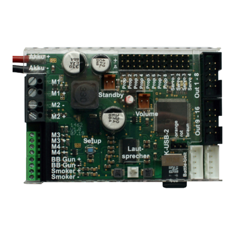
Pin assignment
Connections at SFR-1-HL:
X1
1: Battery + (6 – 12 V)
2: Battery -
X2
Proportional input channel #1 – #8
X3
1 – 8: Switching outputs 1 – 8
9 – 10: Positive pole (Battery +)
X4
1: Smoke generator +
2: Smoke generator -
X5
Servos 1 - 2
X6
1: Turret turn (M4)
2: Turret turn (M4)
3: Gun elevation (M3)
4: BB-Gun
5: Gun elevation (M3)
6: Positive pole (Battery +)
7: Switching output 10 (Status LED)
8: Switching output (MG LED)
X7
Loudspeaker

GB Double Sound Speed Controller SFR-1-HL
10 BEIER-Electronic 01.04.2021
X8
Volume control with poti
X10
Micro SD card
X11
Port for data cable K-USB-2
X12
Motor 1 (left track)
X13
Motor 2 (right track)
X15
1: Input for cannon shot -
2: Input for cannon shot
3: Xenon flash -
4: Xenon flash signal
5: Xenon flash +
X16
1: Battle unit RX +
2: Battle unit RX S
3: Battle unit RX -
4: Battle unit TX S
5: Battle unit TX +

GB Double Sound Speed Controller SFR-1-HL
01.04.2021 BEIER-Electronic 11
-
+
RC receiver
Speaker
4 - 8 Ohm
Servo
1
Servo
2
Data cable
K-USB-2
Volume
10k
Battery
6 - 12 V
+
-
Outputs
minus switching
Button for Setup
Track left
M2
Track right
Servo
Prop #1 (Throttle)
Prop #2 (Steering)
Prop #3 (M3 - Gun elevation)
Prop #4 (M4 - Turret turn)
Prop #5
Prop #6
Prop #7
Prop #8 (S-BUS, SUMD, i-BUS, BTC-1)
+
-
Smoke generator
Xenon flash /
Canon Shoot
IR
Battle unit
Servo
M1
Turret
connector
Main
switch
M.L
M.R
BAT
SM
SP
IR PORT
M.G.FIRE VR
TURN,LIFT,
SHOOT,LAMP
Output 1
Output 2
Output 3
Output 4
Output 5
Output 6
Output 7
Output 8
brown
red
orange
yellow
green
blue
purple
grey
white / black
12
Wiring diagram

GB Double Sound Speed Controller SFR-1-HL
12 BEIER-Electronic 01.04.2021
Installation
For a safe installation of the module, we recommend to use Velcro tape on the SFR-
1-HL cover.
Pay attention not to connect components and conductor tracks with any metal parts!
This may cause a short circuit, which destroys the SFR-1-HL!
Connection
Always switch off power before connecting the module!
The existing connectors are unplugged from the old control unit (RX-18) and plugged
into the corresponding slots of the SFR-1-HL. The old control unit is then completely
removed from the model.
Connection of the supply voltage (battery, via the main switch)
The SFR-1-HL is suitable for a DC voltage of 6 - 12 V. The 2-pin connector with the
battery voltage ("POWER" / "BAT") is inserted into X1 of the SFR-1-HL.
It is very important not to accidentally plug the connector with the battery
voltage into one of the motor connections (X12, X13)! This would destroy the
motor output stage immediately.
Also pay attention to a correct connection of the supply voltage poles! A wrong
connection destroys the SFR-1-HL immediately!!!
Connection of the motors for the main drives
The 2-pin. connector ("M.L") of the motor from the left track is plugged into X12.
The 2-pin. connector ("M.R") of the motor from the right chain is plugged into X13.
Connection of the turret
The 8-pin. Turret connector ("TURN, LIFT, SHOOT, LAMP") is plugged into X6.
For the 4th generation of Heng Long, an adapter cable is required here, since the
assignment of the plug has changed in this version. The adapter cable can be
ordered in our Online-Shop.
Connection of a smoke generator (optional)
The 2-pin. connector ("SM") of a smoke generator is plugged into X4.
Connection of a volume potentiometer (optional):
The 3-pin. connector ("VR") of a volume potentiometer is plugged into X8.

GB Double Sound Speed Controller SFR-1-HL
01.04.2021 BEIER-Electronic 13
Connection of cannon recoil, xenon flash, shot trigger (optional)
The 5-pin. connector ("M.G. FIRE") of a shoot unit is plugged into X15.
Connection of a IR Battle unit (optional)
The 5-pin. Battle unit connector ("IR PORT") is plugged into X16.
Connection of the speaker
The 2-pin. speaker connector ("SP") is plugged into X7.
The red cable is connected to the positive and the black to the negative pole of the
speaker.
The supplied speaker connection cables should not be extended to prevent
interference of the receiver (especially with FM systems)! The loudspeaker cables
should be installed with a maximum of distance to receiver and antenna.
Connection of the minus cable of a cannon recoil unit (optional)
If the (usually red) minus cable, which was soldered directly to the original control
unit on the circuit board, was required for the connection of a canon recoil unit, this
cable can be removed from the old circuit board and can be soldered onto the circuit
board of the SFR-1- HL. For this purpose, there is a golden soldering surface on the
bottom of the SFR-1, next to connector X1 for the battery.
Connection of proportional inputs
To proportional inputs X2/1 - X2/8 up to 8 proportional channels can be connected
to the receiver. 5 servo patch cables are included in the SFR-1-HL delivery.
Additional servo patch cables (15 and 30 cm) can be ordered in our online shop.
The servo patch cables must be connected to the SFR-1-HL with the orange cable
pointing to the center of the board (down) and the brown cable to the edge (up).
Functions of proportional channels:
Prop
Assignment
#1
Throttle channel (with mixer) / throttle channel M1
#2
Steering (with mixer) / throttle channel M2
#3
Free function assignment / steering of M3 (Gun elevation)
#4
Free function assignment / steering of M4 (Turret turn)
#5
Free function assignment / Nautic 1 / EKMFA
#6
Free function assignment / Nautic 2
#7
Free function assignment
#8
Free function assignment /
Sum signals S-BUS, SUMD or i-Bus /
Bluetooth-Controller BTC-1
The channel numbers of the SFR-1-HL do not match with the numbers of your
receiver! So channel #1 of the receiver must not necessarily be connected to

GB Double Sound Speed Controller SFR-1-HL
14 BEIER-Electronic 01.04.2021
channel #1 of the SFR-1-HL. If the throttlestick (to accelerate your model) is for
example at channel #3 on the receiver, you have to connect channel #3 of the
receiver with channel #1 of the SFR-1-HL.
BEC – receiver supply voltage
An additional receiver battery is not required. The SFR-1-HL has a BEC supply
voltage of 5,0 V. The maximum BEC current is 1 A.
In case the BEC voltage of the SFR-1-HL should not be used, the red cable from all
servo cables from proportional channels #1 - #8 must be disconnected!
Connection of switching outputs 1 - 8
The outputs 1 - 8 of the module are located at pin connector X3.
The supplied ribbon cable can be used to connect these outputs. For an easier
connection, the terminals AKL-8 and AKL-8-W can be ordered in our online-shop.
Of course other cables/plugs with a cross section of 0,14 mm² - 0,5 mm² can be
used as well.
The SFR-1-HL is always switching the negative pole to each output and to the
connected load. The negative pole is always connected to the load (see wiring
diagram).
The common positive pole for outputs 1 – 8 are the black and white cables. It is also
possible to connect the load directly to the positive pole of the battery.
Ribon cable assignment:
Output
Ribbon cable (X3)
1
Brown
2
Red
3
Orange
4
Yellow
5
Green
6
Blue
7
Lila
8
Grey
+
White
+
Black
The switched voltage at the outputs (with 100% intensity) is always as high, as the
supply voltage of the SFR-1-HL. For example if the module is supplied with 7,2 V,
only lamps with 7,2 V can be connected.
If LEDs are used at the outputs 1 - 8, series resistors are always required.
Furthermore, attention must be paid to the correct polarity of the LED. The series

GB Double Sound Speed Controller SFR-1-HL
01.04.2021 BEIER-Electronic 15
resistors for the LED’s are depended on the supply voltage, the LED color and the
LED current.
The table below shows the resistance values required for standard LEDs (approx. 15
mA current):
Supply voltage
Series resistors
6 V
270 Ohm
7,2 V
330 Ohm
8,4 V
470 Ohm
9,6 V
510 Ohm
12 V
680 Ohm
In the internet you will find various pages to calculate the necessay resitor value.
If multiple LEDs are connected to one output (e.g. front and rear direction indicators),
it is always better to use separate resistors than to connect the LEDs in series.
Connection of switching outputs 9 - 10
The Outputs 9 (MG LED) and 10 (Status LED) are at X6 for the turret connector.
Here the LEDs are usually already wired in the tank. No additional series resistors
are required for these two outputs. The series resistors for these two outputs are
already integrated on the SFR-1-HL.
Connection of data cable K-USB-2
The data cable K-USB-2 is connected to X11. The brown cable points to the white
connector X16.
The data cable does not supply the module with voltage. For using the data cable,
the SFR-1-HL must be supplied with power via the battery.

GB Double Sound Speed Controller SFR-1-HL
16 BEIER-Electronic 01.04.2021
General remarks for wiring
Always use cables with a core diameter of at least 0,5 mm² for connecting the power
supply and the motors M1 and M2. For all other connections, such as lights you can
use smaller cables such as 0.25 mm².
Unfortunately motors are often strong interference sources, which might disturb other
electronic modules in your model. Therefore all motors should be absolutely
interference-suppressed!
It is important to pay attention to „clean" wire routing. Always use short wires and
avoid any unnecessary loops.

GB Double Sound Speed Controller SFR-1-HL
01.04.2021 BEIER-Electronic 17
Setup (teaching function)
With the teaching function important parameters are synchronised between the radio
and the SFR-1-HL.
During the setup, the neutral positions of all connected channels are transferred to
the encoder positions. For this it is absolutely necessary that all stick or switch
positions are in neutral position at the radio.
The SFR-1-HL is delivered with following standard setting: neutral position (1,5 ms),
minimal position (1,0 ms) and maximal position (2,0 ms).
We recommend to „teach“ the SFR-1-HL with the radio at least once. The motor is
not used during the setup.
The setup process varies depending on the mixer setting. Choose your mixer type in
the Sound-Teacher before doing the setup, see page 57. In our projects and the
delivery setting we use dual mixer #3.
The setup can be started with the blue setup button on the SFR-1-HL board, with the
data cable K-USB-2 and the function „start setup“ (propoportional channel or
nautic/multiswitch).
Setup with dual mixer (delivery setting):
1. Connect throttle channel, steering channel and all proportional channels you
are using.
2. All channels must be in neutral position on your radio. Switch on transmitter
first and then the SFR-1-HL.
3. Activate the setup, with the blue „setup“ button on the SFR-1-HL board, until
the green LED flashes fast. The blue LED flashes once.
4. With correct signals at the throttle channel X2/1 and steering channel X2/2, all
neutral positions are evaluated and stored. In case the red LED is flashing,
the SFR-1-HL can not detect a correct signal at X2/1 or X2/2. Please check all
connections and start the complete setup process again.
5. Press the throttle stick to full throttle for one or two seconds and return to
neutral position. Wait until the blue LED flashes two times and lights
permanently afterwards.
6. Within 20 seconds press the throttle stick down and give full throttle
backwards and return to neutral position. The blue LED flashes three times.
The green and red LED are flashing now fast.
7. Turn the steering completely to the left and return to neutral. The blue LED is
flashing 4 times und stays on afterwards.
8. Within 20 seconds turn the steering completely to the right and return to
neutral. The blue LED flashes 5 times and turns off afterwards.
9. The green LED stays on and the setup is completed.

GB Double Sound Speed Controller SFR-1-HL
18 BEIER-Electronic 01.04.2021
Setup with two separate speed controllers:
1. Connect throttle channel M1, M2 and all proportional channels you are using.
2. All channels and the trim must be in neutral position on your radio. Switch on
transmitter first and then the SFR-1-HL.
3. Activate the setup, with the blue „setup“ button on the SFR-1-HL board, until
the green LED flashes fast. The blue LED flashes once.
4. With correct signals at the throttle channel X2/1 and X2/2, all neutral positions
are evaluated and stored. If the red LED is flashing, the SFR-1-HL can not
detect a correct signal at X2/1 or X2/2. Please check all connections and start
the complete process again.
5. Press the throttle stick for the left motor to full throttle for one or two seconds
and return to neutral position.
6. Wait until the blue LED flashes two times and lights permanently.
7. Within 20 seconds press the throttle stick of the left motor down and give full
throttle backwards and return to neutral position. The blue LED flashes three
times. The green and red LED are flashing fast.
8. Turn the throttle stick of the right motor completely to full throttle and return to
neutral. The blue LED is flashing 4 times und stays on afterwards.
9. Within 20 seconds turn the throttle stick of the right motor completely to full
throttle backwards and return to neutral. The blue LED flashes 5 times and
turns off afterwards.
10.The green LED stays on and the setup is completed.
Loudspeaker
You can connect every loudspeaker to the SFR-1-HL with an impedance of at least 4
Ω and the maximal power you are using. We recommend full range loudspeakers
with 4 or 8 Ω. Higher impedances are also possible, but the volume decreases with
higher impedances.
The maximum power of the loudspeaker and thus the volume of the SFR-1-HL,
correlates with the supply voltage.
To reach a good level of volume and sound quality, install the loudspeaker in a
suitable resonant body (loudspeaker box). A loudspeaker, which lies only on the
table, never reaches optimum sound quality.
Always pay attention to a good air circulation to prevent overheating at the amplifier.
Especially with higher voltages (e.g. above 9,6 V) it might be neccessary to use
active cooling of the SFR-1-HL with a little fan.
For more power, it is possible to connect an additional amplifier. A RCA line level
converter (high/low) with galvanic separation (used at car radios) and a small
capacitor (10 nF) must be connected to the input of the SFR-1-HL amplifier.

GB Double Sound Speed Controller SFR-1-HL
01.04.2021 BEIER-Electronic 19
Volume control
A volume control is possible by an external potentiometer or by different functions
with the radio.
The external potentiometer (10 kΩ) is connected to X8 (see wiring diagram, page
11).
If no potentiometer is connected, the maximum
volume, set in the Sound-Teacher (10 – 100 %) at
Configuration General „Volume (%)” is used.
The volume can be steplessly controlled via a
proportional channel and the "Direct volume control"
setting. A slide switch or knob on the remote control
is recommended with this function.
The volume can also be controlled by a switch. The functions “Volume +“ and
“Volume -“, must be configured in the Sound-Teacher e.g. to a proportional channel
or to a nautic/multiswitch.
General notes to volume
Only transfer sounds with an optimal modulation/volume. Common mistakes are far
too quiet recordings that can not be played properly.
The volume of each sound can also be changed individually. You will find the setting
in your Sound-Teacher on the right side of each sound slot. Values between 10 and
300 % (in relation to the original wav-file) are possible.
If more volume-control options are used at the same time, the lowest volume setting
controls the maximum possible volume at the model.

GB Double Sound Speed Controller SFR-1-HL
20 BEIER-Electronic 01.04.2021
Sounds
All sounds are stored at the SFR-1-HL with our software SFR-1-HL Sound-Teacher, in
so called „slots".
You don’t have to use every slot. If you don’t want e.g. any starting-noise, just keep
the starting-noise slot free.
For “Idling noise“ and “FG1“ (engine sound) you should place a sound, otherwise no
sound in standing and driving is played.
Examples for sound slots:
Sound-Slots
Engine start sound coldstart / warmstart
Idle sound
Vehicle start sound (idling drive)
Vehicle stop sound (drive idling)
Engine stop sound
Engine sound FG1 - 5 (different types: slow down, normal and speed up)
Shift sounds between FG1 - FG5
Reverse warning
Brake sound
Cornering squeak
Indicator noise
Turn warning left / right
Engine sound 2: Engine start/stop sound, idle sound, vehicle start/stop, engine
sound
Additional sounds 1 - 30
Sound from M3 and M4
Sound from Servo 1 - 2 left/right
Cannon shoot
Undervoltage sound
Overcurrent sound
Random sound 1 - 8
Tracks 1-30 for WAV-Player
The engine sound for driving backwards can be different from the sound driving
forward. You can put sounds in these slots, but you don’t have to. If the slot for driving
backward is empty, the sound module will play the normal engine sound. Using slots
for driving backward sounds only make sense if the sounds differ from driving
forwards.
Table of contents
Other BEIER-Electronic Controllers manuals
BEIER-Electronic
BEIER-Electronic UFR-1230 User manual

BEIER-Electronic
BEIER-Electronic SV3-1-8Z User manual

BEIER-Electronic
BEIER-Electronic SV1-2-10Z User manual

BEIER-Electronic
BEIER-Electronic UFR-1230-D User manual

BEIER-Electronic
BEIER-Electronic SFR-1 User manual
BEIER-Electronic
BEIER-Electronic SFR-1-D User manual
