Beissbarth SA 6 Series Technical specifications
Fahrwerkvermessung
Prüfstraße
Vehicle Testing
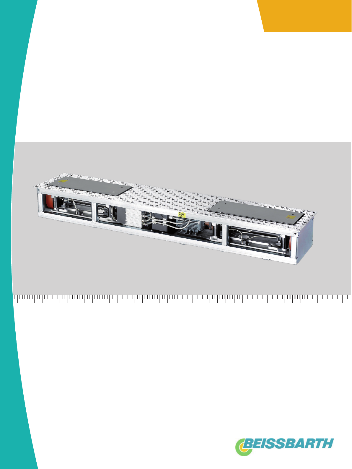
Fahrwerkstester SA / SN 6xx
Chassis Tester SA / SN 6xx
de
Produktbeschreibung
Fahrwerkstester
en
Product description
Suspension tester
fr
Description de produit
Testeur de suspension
es
Descripción del Producto
Probador del suspensión
it
Descrizione del prodotto
Tester sospensioni
sv
Produktbeskrivning
Suspension testare
nl
Produkt beschrijving
Suspensie tester
pt
Descrição do produto
Testador de suspensão
pl
Opis produktu
Tester zawieszenia
cs
Popis výrobku
Tester pozastavení
tr
Ürün tanımı
Süspansiyon test cihazı
zh
产品描述
暂停测试仪
fi
Tuotekuvaus
da
Produktbeskrivelse
Suspension tester
el
Περιγραφή προϊόντος
Διάταξη ελέγχου ανάρτησης
Keskeyttäminen testaaja


1 691 626 220 2015-08-05|Beissbarth GmbH
| SA / SN 6xx | 3 de
Inhaltsverzeichnis Deutsch 4
Contents English 10
Sommaire Français 16
Índice Español 22
Indice Italiano 28
Innehållsförteckning svenska 34
Inhoud Nederlands 40
Contéudo Português 46
Sisällysluettelo - Suomi 52
Indholdsfortegnelse Dansk 58
Spis treści polski 64
Obsah česky 70
İçindekiler Türkçe 76
Πίνακας περιεχομένων Ελληνικά 82
中文目录 88
1 691 626 220 2015-08-05| Beissbarth GmbH
4 | SA / SN 6xx | Verwendete Symbolikde
Inhaltsverzeichnis Deutsch 1. Verwendete Symbolik
1.1 In der Dokumentation
1.1.1 Warnhinweise – Aufbau und Bedeutung
Warnhinweise warnen vor Gefahren für den Benutzer oder
umstehende Personen. Zusätzlich beschreiben Warnhin-
weise die Folgen der Gefahr und die Maßnahmen zur Ver-
meidung. Warnhinweise haben folgenden Aufbau:
Warn-
symbol
SIGNALWORT – Art und Quelle der Gefahr!
Folgen der Gefahr bei Missachtung der aufge-
führten Maßnahmen und Hinweise.
¶Maßnahmen und Hinweise zur Vermeidung
der Gefahr.
Das Signalwort zeigt die Eintrittswahrscheinlichkeit sowie
die Schwere der Gefahr bei Missachtung:
Signalwort Eintrittswahr-
scheinlichkeit
Schwere der Gefahr
bei Missachtung
GEFAHR Unmittelbar drohende
Gefahr Tod oder schwere
Körperverletzung
WAR-
NUNG Mögliche drohende
Gefahr Tod oder schwere
Körperverletzung
VOR-
SICHT Mögliche gefährliche
Situation Leichte
Körperverletzung
1.1.2 Symbole – Benennung und Bedeutung
Symbol Benennung Bedeutung
!Achtung Warnt vor möglichen Sachschäden.
iInformation Anwendungshinweise und andere
nützliche Informationen.
1.
2.
Mehrschrittige
Handlung
Aus mehreren Schritten bestehende
Handlungsaufforderung.
eEinschrittige
Handlung
Aus einem Schritt bestehende
Handlungsaufforderung.
Zwischen-
ergebnis
Innerhalb einer Handlungsaufforderung
wird ein Zwischenergebnis sichtbar.
"Endergebnis Am Ende einer Handlungsaufforderung
wird das Endergebnis sichtbar.
1.2 Auf dem Produkt
!Alle Warnzeichen auf den Produkten beachten und in
lesbarem Zustand halten.
Montage (nur für Kundendienst)
Schwingplatteneinheit nur mit Gewebeschlin-
gen heben. Gewebeschlingen nicht an den
Messplatten befestigen.
1. Verwendete Symbolik 4
1.1 In der Dokumentation 4
1.1.1 Warnhinweise – Aufbau und Bedeutung 4
1.1.2 Symbole – Benennung und Bedeutung 4
1.2 Auf dem Produkt 4
2. Benutzerhinweise 5
2.1 Wichtige Hinweise 5
2.2 Sicherheitshinweise 5
2.3 Mitgeltende Unterlagen 5
2.4 Konfiguration 5
2.5 Elektromagnetische Verträglichkeit (EMV) 5
3. Produktbeschreibung 6
3.1 Bestimmungsgemäße Verwendung 6
3.2 Sonderfunktion SN 680 6
3.3 Ausführungen 6
3.4 Lieferumfang 6
3.5 Sonderzubehör 6
3.6 SA / SN 6xx 6
3.7 Erstinbetriebnahme 7
3.8 Bedienung 7
4. Instandhaltung 7
4.1 Reinigung und Wartung 7
4.2 Wartungsintervalle 7
4.3 Reinigungsarbeiten 7
4.4 Lüfter überprüfen (nur SN 680) 7
5. Prüfen der Betriebssicherheit 8
5.1 Prüfungsintervalle 8
5.2 Sichtprüfung 8
5.3 Sicherheitsprüfungen 8
5.4 Stückprüfung (nur Deutschland) 8
6. Außerbetriebnahme 8
6.1 Vorübergehende Stilllegung 8
6.2 Ortswechsel 8
6.3 Entsorgung und Verschrottung 8
6.3.1 Wassergefährdende Stoffe 8
6.3.2 SA / SN 6xx und Zubehör 8
7. Technische Daten 9
7.1 Umgebungsbedingungen 9
7.2 SA 640 9
7.3 SN 680 9

1 691 626 220 2015-08-05|Beissbarth GmbH
Benutzerhinweise | SA / SN 6xx | 5 de
2. Benutzerhinweise
2.1 Wichtige Hinweise
Wichtige Hinweise zur Vereinbarung über Urheberrecht,
Haftung und Gewährleistung, über die Benutzergruppe
und über die Verpflichtung des Unternehmens finden
Sie in der separaten Anleitung „Wichtige Hinweise und
Sicherheitshinweise zu Beissbarth Test Equipment“.
Diese sind vor Inbetriebnahme, Anschluss und Bedie-
nung von SA / SN 6xx sorgfältig durchzulesen und zwin-
gend zu beachten.
2.2 Sicherheitshinweise
Alle Sicherheitshinweise finden Sie in der separaten
Anleitung „Wichtige Hinweise und Sicherheitshinweise
zu Beissbarth Test Equipment“ (Benutzerhinweise, Be-
stellnummer 1 691 696 920). Diese sind vor Inbetrieb-
nahme, Anschluss und Bedienung von SA / SN 6xx sorg-
fältig durchzulesen und zwingend zu beachten.
2.3 Mitgeltende Unterlagen
Alle Dokumente der Serie BD 6xx / TL / SL 6xx:
Dokument Bestellnummer
Benutzerhinweise 1 691 696 920
Produktbeschreibung:
RBremsenprüfstand BD 6xx
RFahrwerkstester
SA / SN 6xx
RSpurtestplatte ST 600
RIR-Fernbedienung
1 691 606 220
1 691 626 220
1 691 636 220
1 691 696 225
Betriebsanleitung
Rmit Analoganzeige
Rmit PC
Rmit externer Prüfsoftware
1 691 696 020
1 691 706 020
1 691 696 012
Prüfbuch de / en 1 691 696 620 / 1 691 696 621
Kurzanleitungen
RBD 6xx stand alone
RPrüfstraße TL / SL 6xx
1 691 606 420 / 1 691 601 421
1 691 696 420 / 1 691 696 401
Planungsmappen
RBD 6xx stand alone (nicht
BD 66x)
de
en
es
RBD 66x stand alone de/en
RSA / SN 6xx stand alone
RPrüfstraße TL / SL 6xx
de
en
es
905 607 040
905 607 041
1 691 606 302
905 607 050 / 905 607 051
905 627 011 / 905 627 012
905 697 021
905 697 022
1 691 696 303
EG Konformitätserklärung
RBD 6xx stand alone
RPrüfstraße TL / SL 6xx
1 691 696 921
1691 696 921
2.4 Konfiguration
!Alle erforderlichen Konfigurationseinstellungen
sowie die Kalibrierung der Sensoren dürfen nur vom
Kundendienst durchgeführt werden.
2.5 Elektromagnetische Verträglichkeit (EMV)
SA / SN 6xx erfüllt die Kriterien nach EMV-Richtlinie
2014/30/EU.
SA / SN 6xx ist ein Erzeugnis der Klasse B nach
EN 61 000.

1 691 626 220 2015-08-05| Beissbarth GmbH
6 | SA / SN 6xx | Produktbeschreibungde
3. Produktbeschreibung
Zur weiteren bestimmungsgemäßen Verwendung gehört
darüber hinaus:
RAlle zum SA / SN 6xx gehörigen Dokumente lesen
und befolgen.
RDie technischen Daten für SA / SN 6xx und alle seine
Komponenten einhalten.
RBei allen durchgeführten Arbeiten die Sicherheits-
hinweise befolgen.
RSA / SN 6xx nur sachgemäß bedienen.
RBei allen Fahrwerksprüfungen auf eine korrekte Ar-
beitsweise achten.
RDie Wartungsarbeiten rechtzeitig durchführen.
Jede Verwendung, die über diese Angaben hinausgeht,
gilt als nicht bestimmungsgemäß und kann schwere
Personen- oder Sachschäden zur Folge haben. Für hier-
aus entstandene Schäden lehnt der Hersteller jegliche
Haftung ab.
3.1 Bestimmungsgemäße Verwendung
Warnung vor Sach- oder Personenschäden!
Ein sicherer Betrieb von SA / SN 6xx ist bei
nicht bestimmungsgemäßer Verwendung
nicht gewährleistet.
¶SA / SN 6xx nur bestimmungsgemäß ver-
wenden.
¶Keine eigenmächtigen Umbauten und
Veränderungen am SA / SN 6xx.
¶Vorgaben des jeweiligen Fahrzeugherstel-
lers (Bedienungsanleitung) für das Durch-
führen von Fahrwerksprüfungen unbedingt
beachten.
SA / SN 6xx ist Sonderzubehör zu den Bremsenprüf-
ständen der Serie BD 6xx. SA / SN 6xx darf ausschließ-
lich zur Prüfung des technischen Zustands von Radauf-
hängungselementen verwendet werden.
Die Bodenhaftung eines Rades wird bei ungünstigen
Bedingungen vom technischen Zustand der Radaufhän-
gungselemente (Radaufhängung, Radlager, Reifen und
Stoßdämpfer) bestimmt. SA / SN 6xx misst die relative
Bodenhaftung eines Rades nach dem international an-
erkannten EUSAMA-Messprinzip. Das Ergebnis des voll-
ständigen Fahrwerktests ist eine globale Aussage über
die Fahrsicherheit des Fahrzeugs.
iSA / SN 6xx kann nur in Verbindung mit einem Brem-
senprüfstand der BD 6xx-Serie betrieben werden.
3.2 Sonderfunktion SN 680
Die Sonderfunktion Geräuschdiagnose darf ausschließ-
lich zur Identifizierung der Ursache von mechanischen
Störgeräuschen im Fahrzeug verwendet werden, z.B.
von Klappergeräuschen.
3.3 Ausführungen
Ausführung Fahrwerkstester Geräuschdiagnose
SA 640 x
SN 680 x x
Tab. 1: Ausführungen SA / SN 6xx
3.4 Lieferumfang
Im Lieferumfang sind folgende Komponenten enthalten:
RFahrwerkstester,
RAnschlusskabel,
RSpanneisen-Set und Befestigungsmaterial.
3.5 Sonderzubehör
Als Sonderzubehör für SA / SN 6xx sind folgende Kom-
ponenten erhätlich:
Fundamentarbeiten:
Komponente Bestellnummer
Dübelset für SA 640 935 623 012
Kantenschutzrahmen für
SA / SN 6xx
935 624 005
Kantenschutzrahmen Prüfstraße 935 694 001
Einbauwanne Prüfstraße 935 604 170
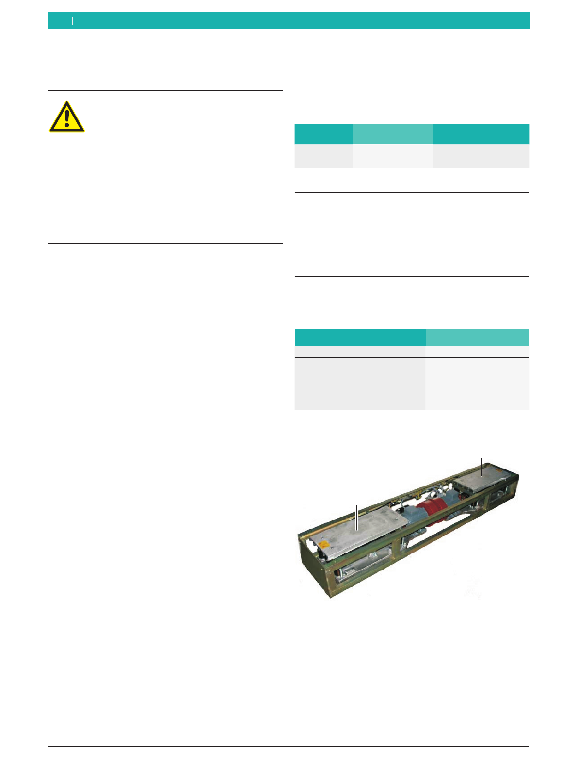
3.6 SA / SN 6xx
1
2
Fig. 1: SA / SN 6xx
1 Schwingplatte links
2 Schwingplatte rechts
1 691 626 220 2015-08-05|Beissbarth GmbH
Instandhaltung | SA / SN 6xx | 7 de
3.7 Erstinbetriebnahme
!Ausschließlich ein autorisierter Servicetechniker darf
die Erstinbetriebnahme durchführen.
iDie Montagevoraussetzungen müssen erfüllt sein,
bevor ein Servicetechniker mit der Installation be-
ginnt. Weitere Hinweise finden Sie in der Planungs-
mappe.
!Die Angaben in der Planungsmappe sind Mindestan-
gaben, um die korrekte Installation von SA / SN 6xx
zu gewährleisten. Spezielle nationale Gesetze,
Richtlinien und Normen sind bei der Umsetzung der
Vorgaben zu beachten! Die Beissbarth GmbH haftet
nicht für Schäden, die durch Nichtbeachtung natio-
naler Regelungen entstehen.
3.8 Bedienung
Die Bedienung von SA / SN 6xx ist in der zugehörigen
Betriebsanleitung beschrieben.
Warnung vor Restgefahren!
Bei der Bedienung von SA / SN 6xx können
Restgefahren nicht ausgeschlossen wer-
den.
¶Beachten Sie die Sicherheitshinweise!
Siehe "Benutzerhinweise".
¶Tragen Sie persönliche Schutzausrüs-
tung!
SA / SN 6xx besteht aus zwei Schwingplatten, die über
einen Exzenterantrieb von einem Elektromotor angetrie-
ben werden.
Die Schwingplatten führen nacheinander eine sinusför-
migen Bewegung mit variabler Frequenz und mit kons-
tanter Amplitude aus.
Sensoren messen die entstehende sinusförmige dyna-
mische Radlast im Frequenzbereich von 0…25 Hz.
Geräuschsimulator SN 680:
SN 680 ist mit Ventilatoren und integrierter Lüftungs-
steuerung ausgestattet.
iDie Lüfter werden in Abhängigkeit von der Motortem-
peratur ein- und ausgeschaltet. Die Einschalttempe-
ratur der Lüfter ist frei konfigurierbar.
Für den Fall der Überhitzung der Motoren ist eine
Sicherheits-Abschaltfunktion integriert.
4. Instandhaltung
Dieses Kapitel beschreibt die Instandhaltungsarbeiten,
die vom Betreiber durchgeführt werden können.
4.1 Reinigung und Wartung
!Ausschließlich autorisiertes Wartungspersonal darf
Wartungs- und Reparaturarbeiten durchführen. Hal-
ten Sie die Sicherheitsmaßnahmen für Wartung und
Instandhaltung ein, die in Kapitel „Sicherheitshinwei-
se“ beschrieben sind.
4.2 Wartungsintervalle
Halten Sie die folgenden Intervalle für Wartungsarbei-
ten und Prüfungen ein.
Komponente
Täglich
Monatlich
Jährlich
Reinigungsarbeiten x x
SN 680: Lüfter überprüfen x
4.3 Reinigungsarbeiten
!Keine Hochdruckreiniger verwenden
Komponente Reinigungshinweise
SA / SN 6xx Verunreinigungen (z.B. Steine) von den
Schwingplatten und der Abdeckplatte
abkehren oder absaugen, um einen ein-
wandfreien Betrieb zu gewährleisten.
Wasserablauf Darauf achten, dass der Wasserablauf
freien Abfluss hat und nicht verstopfen
kann.
4.4 Lüfter überprüfen (nur SN 680)
1. Hauptschalter ausschalten und gegen Wiederein-
schalten sichern.
2. Abdeckplatte:
12 Innen-Sechskantschrauben lösen und Abdeckplat-
te entfernen.
3. Die Lüfter beider Motoren auf Leichtgängigkeit über-
prüfen. Verschmutzungen absaugen.
4. Abdeckplatte wieder montieren.
5. Hauptschalter wieder einschalten.
6. Lüfter auf Funktion prüfen.
1 691 626 220 2015-08-05| Beissbarth GmbH
8 | SA / SN 6xx | Prüfen der Betriebssicherheitde
5. Prüfen der Betriebs-
sicherheit
5.1 Prüfungsintervalle
Komponente
Täglich
Jährlich
Alle 2 Jahre
Sichtprüfung x
Sicherheitsprüfung x
Stückprüfung (nur Deutschland) x
5.2 Sichtprüfung
¶Bei jedem Einschalten eine Sichtprüfung durch-
führen.
iDie eingebaute Elektronik überprüft die sicherheits-
relevanten Funktionen bei jedem Einschalten auto-
matisch.
5.3 Sicherheitsprüfungen
Sicherheitsprüfung Deutschland
¶Der Betreiber muss mindestens einmal jährlich die
sicherheitsrelevanten Einrichtungen der Anlage über-
prüfen (BGV A1, §39 Abs. 1 und 3).
Sicherheitsprüfung international
¶Der Betreiber sollte mindestens einmal jährlich die
sicherheitsrelevanten Einrichtungen der Anlage über-
prüfen. Die gesetzlichen Vorgaben eines Landes sind
hierzu unbedingt zu beachten.
5.4 Stückprüfung (nur Deutschland)
Die Stückprüfung muss von einem geprüften und autori-
sierten Kundendienstmonteur durchgeführt werden:
RVor der ersten Inbetriebnahme.
RAlle 2 Jahre (Wiederholungsprüfung).
RUnmittelbar (innerhalb von 4 Wochen) nach einer
Reparatur von SA / SN 6xx, wenn Baugruppen ausge-
tauscht wurden, die für die Messung relevant sind.
!Der Termin für die nächste Stückprüfung muss gut
sichtbar an SA / SN 6xx angebracht sein.
6. Außerbetriebnahme
6.1 Vorübergehende Stilllegung
Bei längerem Nichtbenutzen:
6.2 Ortswechsel
¶Bei Weitergabe von SA / SN 6xx die im Lieferumfang
vorhandene Dokumentation vollständig mit übergeben.
¶SA / SN 6xx nur in Originalverpackung oder gleich-
wertiger Verpackung transportieren.
¶Hinweise zur Erstinbetriebnahme beachten.
¶Elektrischen Anschluss trennen.
6.3 Entsorgung und Verschrottung
6.3.1 Wassergefährdende Stoffe
!Öle und Fette sowie ölhaltige und fetthaltige Abfälle
(z. B. Filter) sind wassergefährdende Stoffe.
1. Wassergefährdende Stoffe nicht in die Kanalisation
gelangen lassen.
2. Wassergefährdende Stoffe gemäß den geltenden
Vorschriften entsorgen.
6.3.2 SA / SN 6xx und Zubehör
1. SA / SN 6xx vom Stromnetz trennen und Netzan-
schlussleitung entfernen.
2. SA / SN 6xx zerlegen, nach Material sortieren und
gemäß den geltenden Vorschriften entsorgen.
SA / SN 6xx unterliegt der europäischen
Richtlinie 2012/19/EU (WEEE).
Elektro- und Elektronik-Altgeräte einschließ-
lich Leitungen und Zubehör sowie Akkus und
Batterien müssen getrennt vom Hausmüll
entsorgt werden.
¶Nutzen Sie zur Entsorgung die zur Verfügung
stehenden Rückgabesysteme und Sammel-
systeme.
¶Mit der ordnungsgemäßen Entsorgung von
SA / SN 6xx vermeiden Sie Umweltschäden
und eine Gefährdung der persönlichen
Gesundheit.
1. Hauptschalter ausschalten und mit Vorhängeschloss
sichern.
2. SA / SN 6xx gegen missbräuchliche Nutzung sichern.
Warnschild aufstellen.
1 691 626 220 2015-08-05|Beissbarth GmbH
Technische Daten | SA / SN 6xx | 9 de
7. Technische Daten
7.1 Umgebungsbedingungen
Bezeichnung Wert
Betriebstemperatur -10…+50 °C
Lagertemperatur -10…+50 °C
relative Luftfeuchtigkeit
(keine Kondensation) < 85 %
7.2 SA 640
Messsystem:
Bezeichnung Wert
Messsystem Biegebalken mit Dehn-
messstreifen (DMS)
Grunddaten:
Bezeichnung Wert
Abmessungen (L x B x H) 440 x 2360 x 280 mm
Abmessungen Schwingplatte (L x B) 690 x 273 mm
Größte Prüfbreite 2200 mm
Kleinste Prüfbreite 820 mm
Gewicht ca. 260 kg
Zulässige Prüflast pro Achse 2000 kg
Zulässige max. Überfahrlast pro Achse 4000 kg
Emissionsschalldruckpegel am Ar-
beitsplatz
≤70 dB(A)
Schutzart (nach DIN 40 050) IP 54
Leistungsdaten
Bezeichnung Wert
Spannungsversorgung 3 x 230 VAC / 11,4A / 50-60Hz
3 x 400 VAC / 6,6A / 50-60Hz
Absicherung (bauseits) 3 x 20 A / C-3polig (230 V)
3 x 20 A / C-3polig (400 V)
Zuleitung (bauseits) 4 x 2,5 mm (230V)
5 x 2,5 mm (400 V)
Nennleistung der Antriebsmo-
toren
2 x 2,5 kW
Motordrehzahl 1360 1/min
cos f der Motoren 0,75
Max. Prüffrequenz 25 Hz
Hub 6 mm
7.3 SN 680
Messsystem:
Bezeichnung Wert
Messsystem Biegebalken mit Dehn-
messstreifen (DMS)
Grunddaten:
Bezeichnung Wert
Abmessungen (L x B x H) 440 x 2360 x 280 mm
Abmessungen Schwingplatte (L x B) 690 x 273 mm
Gewicht ca. 270 kg
Größte Prüfbreite 2200 mm
Kleinste Prüfbreite 820 mm
Zulässige Prüflast pro Achse 1650 kg
Zulässige max. Überfahrlast pro
Achse
4000 kg
Emissionsschalldruckpegel am Ar-
beitsplatz
≤70 dB(A)
Schutzart (nach DIN 40 050) IP 54
Leistungsdaten:
Bezeichnung Wert
Spannungsversorgung
(über Hauptschalterbox)
3 x 230 VAC / 14,2A / 50-60Hz
3 x 400 VAC / 8,2A / 50-60Hz
Absicherung (bauseits) 3 x 20 A / C-3polig (230 V)
3 x 20 A / C-3polig (400 V)
Zuleitung (bauseits) 4 x 2,5 mm (230V)
5 x 2,5 mm (400 V)
Nennleistung der Antriebsmo-
toren
2 x 3,0 kW
Motordrehzahl 1420 1/min
cos f der Motoren 0,7
Prüffrequenz Fahrwerkstester 0…30 Hz
Prüffrequenz Geräuschsimu-
lator
10…30 Hz
Abschaltgrenze der Übertem-
peratursicherung
90 °C
1 691 626 220 2015-08-05| Beissbarth GmbH
10 | SA / SN 6xx | Symbols useden
Contents English 1. Symbols used
1.1 In the documentation
1.1.1 Warning notices -
Structure and meaning
Warning notices warn of dangers to the user or people
in the vicinity. Warning notices also indicate the con-
sequences of the hazard as well as preventive action.
Warning notices have the following structure:
Warning
symbol
KEY WORD – Nature and source of hazard!
Consequences of hazard in the event of failu-
re to observe action and information given.
¶Hazard prevention action and information.
The key word indicates the likelihood of occurrence and
the severity of the hazard in the event of non-observan-
ce:
Key word Probability of
occurrence
Severity of danger if inst-
ructions not observed
DANGER Immediate impen-
ding danger Death or severe injury
WAR-
NING Possible impending
danger Death or severe injury
CAUTION Possible dangerous
situation Minor injury
1.1.2 Symbols in this documentation
Symbol Designation Explanation
!Attention Warns about possible property damage.
iInformation Practical hints and other
useful information.
1.
2.
Multi-step
operation
Instruction consisting of several steps.
eOne-step
operation
Instruction consisting of one step.
Intermediate
result
An instruction produces a visible inter-
mediate result.
"Final result There is a visible final result on com-
pletion of the instruction.
1.2 On the product
!Observe all warning notices on products and ensure
they remain legible.
Assembly (Service personnel only)
Only use fabric slings to lift the shaker
plate unit. Do not attach fabric slings to the
measurement plates.
1. Symbols used 10
1.1 In the documentation 10
1.1.1 Warning notices -
Structure and meaning 10
1.1.2 Symbols in this documentation 10
1.2 On the product 10
2. User information 11
2.1 Important notes 11
2.2 Safety instructions 11
2.3 Other applicable documentation 11
2.4 Configuration 11
2.5 Electromagnetic compatibility (EMC) 11
3. Product description 12
3.1 Intended use 12
3.2 SN 680 special function 12
3.3 Versions 12
3.4 Scope of delivery 12
3.5 Special accessories 12
3.6 SA / SN 6xx 12
3.7 Commissioning 13
3.8 Operation 13
4. Maintenance 13
4.1 Cleaning and servicing 13
4.2 Maintenance intervals 13
4.3 Cleaning 13
4.4 Fan check (SN 680 only) 13
5. Checking operational
reliability 14
5.1 Test intervals 14
5.2 Visual inspection 14
5.3 Safety checks 14
5.4 Routine test (Germany only) 14
6. Decommissioning 14
6.1 Temporary shutdown 14
6.2 Change of location 14
6.3 Disposal and scrapping 14
6.3.1 Substances hazardous to water 14
6.3.2 SA / SN 6xx and accessories 14
7. Technical data 15
7.1 Ambient conditions 15
7.2 SA 640 15
7.3 SN 680 15

1 691 626 220 2015-08-05|Beissbarth GmbH
User information | SA / SN 6xx | 11 en
2. User information
2.1 Important notes
Important information on copyright, liability and war-
ranty provisions, as well as on equipment users and
company obligations, can be found in the separate
manual "Important notes on and safety instructions for
Beissbarth Test Equipment". These instructions must be
carefully studied prior to start-up, connection and op-
eration of the SA / SN 6xx and must always be heeded.
2.2 Safety instructions
All the pertinent safety instructions can be found in the
separate manual "Important notes on and safety in-
structionsforBeissbarthTestEquipment"(userinformation,
order number 1 691 696 920). These instructions must
be carefully studied prior to start-up, connection and
operation of the SA / SN 6xx and must always be heeded.
2.3 Other applicable documentation
All documents for series BD 6xx / TL / SL 6xx:
Document Order number
User information 1 691 696 920
Product description
RBrake tester BD 6xx
RSuspensiontesterSA/SN6xx
RSide slip tester ST 600
RIR remote control
1 691 606 220
1 691 626 220
1 691 636 220
1 691 696 225
Operating instructions
Rwith analog display
Rwith PC
Rwith external test software
1 691 696 020
1 691 706 020
1 691 696 012
Test log book de / en 1 691 696 620 / 1 691 696 621
Brief instructions de / en
RBD 6xx stand alone
RTestlane TL / SL 6xx
1 691 606 420 / 1 691 601 421
1 691 696 420 / 1 691 696 401
Planning folders
RBD 6xx stand alone
(not BD 66x)
de
en
es
RBD 66x stand alone de/en
RSA / SN 6xx stand alone
RTestlane TL / SL 6xx
de
en
es
905 607 040
905 607 041
1 691 606 302
905 607 050 / 905 607 051
905 627 011 / 905 627 012
905 697 021
905 697 022
1 691 696 303
EU Declaration of Conformity
RBD 6xx stand alone
RTestlane TL / SL 6xx
1 691 696 921
1691 696 921
2.4 Configuration
!Only Service personnel are authorized to make all the nec-
essary configuration settings and calibrate the sensors.
2.5 Electromagnetic compatibility (EMC)
The SA / SN 6xx satisfies the requirements of the EMC di-
rective 2014/30/EU.
The SA / SN 6xx is a class B product as per EN 61 000.
1 691 626 220 2015-08-05| Beissbarth GmbH
12 | SA / SN 6xx | Product descriptionen
3. Product description
The following also applies with regard to the intended
use:
RRead and observe all the documents accompanying
the SA / SN 6xx.
REnsure compliance with the technical data for the
SA / SN 6xx and all its components.
RAlways heed the safety instructions when performing
work.
ROnly operate the SA / SN 6xx in the proper manner.
REnsure correct working procedures when performing
all suspension tests.
RPerform maintenance work in due time.
Any application beyond the scope of these specifica-
tions does not constitute the intended purpose and
could result in serious injuries or damage. The manu-
facturer cannot accept any liability for injury or damage
arising from such usage.
3.1 Intended use
Warning of possible damage or injury!
Safe operation of the SA / SN 6xx
cannot be guaranteed for applications not
conforming to the intended purpose.
¶The SA / SN 6xx is only ever to be
employed for the intended purpose.
¶The user is not authorized to convert or
modify the SA / SN 6xx.
¶Always heed the specifications of the
corresponding vehicle manufacturer
(operating instructions) as regards the
performance of suspension tests.
The SA / SN 6xx is a special accessory for series
BD 6xx brake dynamometers. The SA / SN 6xx
is only to be used for checking the technical condition
of suspension elements.
Under unfavourable conditions, the road surface
adhesion of a wheel is governed by the technical
condition of the suspension elements (suspension
system, wheel bearings, tires and shock absorbers).
The SA / SN 6xx measures the relative road
surface adhesion of a wheel on the basis of the
internationally recognized EUSAMA principle. The
results of the full chassis test provide an overall
assessment of the road safety of the vehicle.
iThe SA / SN 6xx can only be operated in conjunction
with a series BD 6xx brake dynamometer.
3.2 SN 680 special function
The special noise diagnosis function is only to be used
to identify the cause of mechanical noise in the vehicle,
e.g. rattling noise.
3.3 Versions
Version
Suspension tester
Noise diagnosis
SA 640 x
SN 680 x x
Tab. 1: Versions of SA / SN 6xx
3.4 Scope of delivery
The scope of delivery includes the following
components:
RSuspension tester
RConnecting cable
RSet of clamping fixtures and fastening materials
3.5 Special accessories
The following components are available as special
accessories for the SA / SN 6xx:
Foundation work:
Component Order number
Set of dowels for SA 640 1 691 621 001
Edge protection frame for
SA / SN 6xx
1 691 622 002
Edge protection frame for test
lane
1 691 602 001
Mounting trough for test lane 1 691 602 001
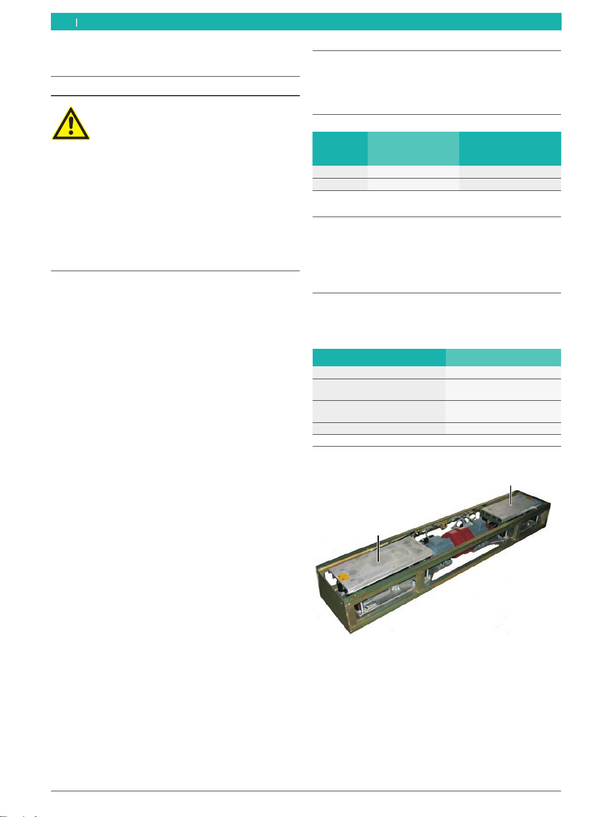
3.6 SA / SN 6xx
1
2
Fig. 1: SA / SN 6xx
1 Left shaker plate
2 Right shaker plate

1 691 626 220 2015-08-05|Beissbarth GmbH
Maintenance | SA / SN 6xx | 13 en
3.7 Commissioning
!Commissioning is only to be performed by an autho-
rized service engineer.
iThe installation conditions must be satisfied before
the start of erection work by a service engineer. Fur-
ther information can be found in the planning folder.
!The specifications given in the planning folder are
minimum requirements designed to ensure cor-
rect installation of the SA / SN 6xx. Any particular
local legislation, guidelines and standards must
be observed with regard to the specifications.
Beissbarth GmbH does not accept any liability for
damage arising from non-observance of local regula-
tions.
3.8 Operation
Operation of the SA / SN 6xx is described in the operating
instructions.
Remaining hazard warning
The possibility of remaining hazards cannot
be excluded.
¶Observe the safety instructions. Refer to
"User information".
¶Wear protective clothing and equipment.
The SA / SN 6xx consists of two shaker plates
operated by an electric motor via an eccentric drive.
The shaker plates consecutively execute sinusoidal
motion with variable frequency and constant amplitude.
The sensors measure the resultant sinusoidal dynamic
wheel load in the frequency range 0…25 Hz.
Noise simulator SN 680:
The SN 680 is equipped with fans and an integrated
ventilation control system.
iThe fans are switched on and off as a function of
motor temperature. The cut-in temperature of the
fans can be configured by the user.
An integrated safety cut-out function is provided to
guard against overheating of the motors.
4. Maintenance
This Section describes the maintenance work which
can be performed by the user.
4.1 Cleaning and servicing
!Servicing and repair work is only to be performed
by authorized service personnel. Ensure compliance
with the safety precautions for service and main-
tenance as described in the "Safety instructions"
Section.
4.2 Maintenance intervals
Observe the following intervals for maintenance work
and testing.
Component
Daily
Monthly
Annually
Cleaning x x
SN 680: Fan check x
4.3 Cleaning
!Do not use high-pressure cleaners.
Component Notes on cleaning
SA / SN 6xx To ensure proper operation, brush off or extract
any contamination (e.g. stones) from the shaker
plates and the cover plate.
Water drain Make sure the water drain is not obstructed and
cannot become clogged.
4.4 Fan check (SN 680 only)
1. Switch off the master switch and secure against
renewed switch-on.
2. Cover plate:
Slacken off the 12 hexagon socket head bolts and
remove the cover plate.
3. Check the fans of both motors for freedom of
movement. Extract any contamination.
4. Re-fit the cover plate.
5. Switch the master switch back on.
6. Check fan operation.

1 691 626 220 2015-08-05| Beissbarth GmbH
14 | SA / SN 6xx | Checking operational reliabilityen
5. Checking operational
reliability
5.1 Test intervals
Component
Daily
Annually
Every 2 years
Visual inspection x
Safety check x
Routine test (Germany only) x
5.2 Visual inspection
¶Always perform a visual inspection on switching on
the device.
iThe functions of relevance to safety are automatically
checked by the integral electronics each time the
device is switched on.
5.3 Safety checks
Safety check for Germany
¶The operator must check the system components of
relevance to safety at least once a year (BGV A1,
§39 para. 1 and 3).
International safety check
¶The operator should check the system components
of relevance to safety at least once a year. Local
legislation must be heeded.
5.4 Routine test (Germany only)
Routine testing must be conducted by an authorized
service engineer as follows:
RPrior to initial commissioning.
REvery 2 years (repeat test).
RImmediately (within 4 weeks) following SA / SN 6xx
repair work involving the replacement of assemblies
of relevance to measurement.
!The deadline for the next routine test must be clearly
indicated on the SA / SN 6xx.
6. Decommissioning
6.1 Temporary shutdown
In the event of lengthy periods of non-use:
6.2 Change of location
¶If the SA / SN 6xx is passed on, all the documentation
included in the scope of delivery must be handed over
together with the unit.
¶The SA / SN 6xx is only ever to be transported in the
original or equivalent packaging.
¶Unplug the electrical connection.
¶Heed the notes on initial commissioning.
6.3 Disposal and scrapping
6.3.1 Substances hazardous to water
!Oils and greases as well as refuse containing oil and
grease (e.g. filters) represent a hazard to water.
1. Substances hazardous to water must not be allowed
to enter the sewage system.
2. Substances hazardous to water must be disposed of
in accordance with the applicable regulations.
6.3.2 SA / SN 6xx and accessories
1. Disconnect the SA / SN 6xx from the mains and detach
the power cord.
2. Dismantle the SA / SN 6xx and sort out and dispose of
the different materials in accordance with the ap-
plicable regulations.
The SA / SN 6xx is subject to the European
directive 2002/96/EC (WEEE).
Dispose of used electrical and electronic
devices, including cables, accessories and
batteries, separately from household waste.
¶Make use of the local return and collection
systems for disposal.
¶
Proper disposal of SA / SN 6xx prevents en
-
vironmental pollution and possible health
hazards.
1. Switch off the master switch and secure with a
padlock.
2. Secure the SA / SN 6xx to prevent unauthor-
ized use. Erect a warning sign.
1 691 626 220 2015-08-05|Beissbarth GmbH
Technical data | SA / SN 6xx | 15 en
7. Technical data
7.1 Ambient conditions
Designation Value
Operating temperature -10…+50 °C
Storage temperature -10…+50 °C
Relative humidity
(no condensation)
< 85 %
7.2 SA 640
Measurement system:
Designation Value
Measurement system Bending bar with strain
gauge
Basic data:
Designation Value
Dimensions (L x W x H) 440 x 2360 x 280 mm
Shaker plate dimensions (L x W) 690 x 273 mm
Maximum test width 2200 mm
Minimum test width 820 mm
Weight approx. 260 kg
Permissible test load per axle 2000 kg
Max. permissible driveover load per
axle
4000 kg
Workplace emission sound pressure
level as
≤ 70 dB(A)
Degree of protection (as per
DIN 40 050)
IP 54
Operating data:
Designation Value
Power supply 3 x 230 VAC / 11,4A / 50-60Hz
3 x 400 VAC / 6,6A / 50-60Hz
Fuse protection (customer) 3 x 20 A / C 3-pole (230 V)
3 x 20 A / C 3-pole (400 V)
Supply cable (customer) 4 x 2,5 mm (230V)
5 x 2,5 mm (400 V)
Rated power of drive motors 2 x 2,5 kW
Motor speed 1360 1/min
cos f of motors 0,75
Max. test frequency 25 Hz
Stroke 6 mm
7.3 SN 680
Measurement system:
Designation Value
Measurement system Bending bar with strain
gauge
Basic data:
Designation Value
Dimensions (L x W x H) 440 x 2360 x 280 mm
Shaker plate dimensions (L x W) 690 x 273 mm
Weight approx. 270 kg
Maximum test width 2200 mm
Minimum test width 820 mm
Permissible test load per axle 1650 kg
Max. permissible driveover load per
axle
4000 kg
Workplace emission sound pressure
level as
≤70 dB(A)
Degree of protection (as per
DIN 40 050)
IP 54
Operating data:
Designation Value
Power supply
(via master switch box)
3 x 230 VAC / 14,2A / 50-60Hz
3 x 400 VAC / 8,2A / 50-60Hz
Fuse protection (customer) 3 x 20 A / C 3-pole (230 V)
3 x 20 A / C 3-pole (400 V)
Supply cable (customer) 4 x 2,5 mm (230V)
5 x 2,5 mm (400 V)
Rated power of drive motors 2 x 3,0 kW
Motor speed 1420 1/min
cos f of motors 0,7
Test frequency of suspension
tester
0…30 Hz
Noise simulator test
frequency
10…30 Hz
Cut-out limit of
overtemperature safeguard
90 °C

1 691 626 220 2015-08-05| Beissbarth GmbH
16 | SA / SN 6xx | Symboles utilisésfr
Sommaire Français 1. Symboles utilisés
1.1 Dans la documentation
1.1.1 Avertissements – Conception et signification
Les avertissements mettent en garde contre les dangers
pour l’utilisateur et les personnes présentes à proximité.
En outre, les avertissements décrivent les conséquences
du danger et les mesures préventives. La structure des
avertissements est la suivante :
Symbole
d’avertisse-
ment
MOT CLÉ - Nature et source du danger !
Conséquences du danger en cas de non-
observation des mesures et indications.
¶Mesures et indications pour la pré-
vention du danger.
Le mot clé indique la probabilité de survenue ainsi que
la gravité du danger en cas de non-observation :
Mot clé Probabilité
de survenue
Gravité du danger en
cas de non-observation
DANGER Danger direct Mort ou blessure
corporelle grave
AVERTISSE-
MENT Danger poten-
tiel Mort ou blessure
corporelle grave
PRUDENCE Situation potenti-
ellement dange-
reuse
Blessure corporelle
légère
1.1.2 Symboles – désignation et signification xxx
Symbole Désignation Signification
!Attention Signale des dommages matériels
potentiels.
iInformation Consignes d'utilisation et autres
informations utiles.
1.
2.
Procédure à plu-
sieurs étapes
Instruction d'exécution d’une opé-
ration comportant plusieurs étapes.
eProcédure à une
étape
Instruction d'exécution d’une opé-
ration comportant une seule étape.
Résultat inter-
médiaire
Un résultat intermédiaire est visib-
le au cours d’une procédure.
"Résultat final Le résultat final est présenté à la
fin de la procédure.
1.2 Sur le produit
!Observer tous les avertissements qui figurent sur les
produits et les maintenir lisibles.
Montage (réservé au service clients)
Ne soulever la plaque oscillante qu’avec des
sangles textiles. Ne pas fixer les sangles tex-
tiles aux plaques de mesure.
1. Symboles utilisés 16
1.1 Dans la documentation 16
1.1.1 Avertissements – Conception et signi-
fication 16
1.1.2 Symboles – désignation et significa-
tion xxx 16
1.2 Sur le produit 16
2. Consignes d’utilisation 17
2.1 Remarques importantes 17
2.2 Consignes de sécurité 17
2.3 Autres documents à observer 17
2.4 Configuration 17
2.5 Compatibilité électromagnétique (CEM) 17
3. Description du produit 18
3.1 Utilisation conforme 18
3.2 Fonction spéciale SN 680 18
3.3 Versions 18
3.4 Fournitures 18
3.5 Accessoires spéciaux 18
3.6 SA / SN 6xx 18
3.7 Première mise en service 19
3.8 Utilisation 19
4. Maintenance 19
4.1 Nettoyage et entretien 19
4.2 Intervalles d’entretien 19
4.3 Nettoyage 19
4.4 Contrôler les ventilateurs
(SN 680 seulement) 19
5. Contrôle de la sécurité de fonctionnement 20
5.1 Intervalles de contrôle 20
5.2 Contrôle visuel 20
5.3 Contrôles de sécurité 20
5.4 Contrôle individuel (Allemagne uniquement) 20
6. Mise hors service 20
6.1 Mise hors service provisoire 20
6.2 Déplacement 20
6.3 Elimination et mise au rebut 20
6.3.1 Substances dangereuses
pour les eaux xxx 20
6.3.2 SA / SN 6xx et accessoires 20
7. Caractéristiques techniques 21
7.1 Conditions d'environnement 21
7.2 SA 640 21
7.3 SN 680 21

1 691 626 220 2015-08-05|Beissbarth GmbH
Consignes d’utilisation | SA / SN 6xx | 17 fr
2. Consignes d’utilisation
2.1 Remarques importantes
Vous trouverez des remarques importantes sur ce qui a été con-
venu en matière de droits d'auteur, de responsabilité et de ga-
rantie, sur le groupe d'utilisateurs et les obligations incombant
à l'entrepreneur, dans le manuel séparé "Remarques impor-
tantes et consignes de sécurité pour Beissbarth Test Equipment".
Avant la mise en service, le raccordement et l'utilisation du
SA / SN 6xx, il est impératif de lire et d'appliquer ces remarques.
2.2 Consignes de sécurité
Vous trouverez toutes les consignes de sécurité dans la noti-
ce séparée "Remarques importantes et consignes de sécu-
rité pour Beissbarth Test Equipment" (consignes d’utilisation,
référence de commande 1 691 696 920). Avant la mise en
service, le raccordement et l'utilisation du SA / SN 6xx, il est
impératif de lire et d'appliquer ces remarques.
2.3 Autres documents à observer
Tous les documents dans la série BD 6xx / TL / SL 6xx:
Document Référence de commande
Consignes d’utilisation 1 691 696 920
Description de produit
RBanc d’essai de freinage
BD 6xx
RTesteur de suspension
SA / SN 6xx
RPlaque de test de ripage
ST 600
RTélécommande IR
1 691 606 220
1 691 626 220
1 691 636 220
1 691 696 225
Notice d’utilisation
Ravec afficheur analogique
Ravec PC
Ravec logiciel de test externe
1 691 696 020
1 691 706 020
1 691 696 012
Manuel de contrôle de / en 1 691 696 620 / 1 691 696 621
Notice simplifiée de / en
RBD 6xx stand alone
RTestlane TL / SL 6xx
1 691 606 420 / 1 691 601 421
1 691 696 420 / 1 691 696 401
Dossiers d’étude de / en
RBD 6xx stand alone
(pas BD 66x)
de
en
es
RBD 66x stand alone de/en
RSA / SN 6xx stand alone
RTestlane TL / SL 6xx
de
en
es
905 607 040
905 607 041
1 691 606 302
905 607 050 / 905 607 051
905 627 011 / 905 627 012
905 697 021
905 697 022
1 691 696 303
Déclaration de conformité CE
RBD 6xx
RTL / SL 6xx
1 691 696 921
1691 696 921
2.4 Configuration
!Tous les réglages de configuration nécessaires de
même que l’étalonnage des capteurs doivent être
effectués uniquement par le SAV.
2.5 Compatibilité électromagnétique (CEM)
Le SA / SN 6xx est conforme aux critères de la directive de
CEM 2014/30/EU.
Le SA / SN 6xx est un produit de la catégorie B selon EN 61 000.
1 691 626 220 2015-08-05| Beissbarth GmbH
18 | SA / SN 6xx | Description du produitfr
3. Description du produit
L’utilisation conforme englobe également :
RLa lecture et l’observation de tous les documents
afférents au SA / SN 6xx.
RLe respect des caractéristiques techniques du
SA / SN 6xx et de tous ses composants.
RObserver les consignes de sécurité lors de tous les
travaux effectués.
RUtiliser toujours le SA / SN 6xx dans les règles.
RTous les contrôles de châssis doivent être effectués
en travaillant dans les règles.
REffectuer les opérations d’entretien à temps.
Toute utilisation qui dépasse le cadre de ces indications
est considérée comme non conforme et peut occasi-
onner des dommages corporels et matériels graves.
Le fabricant décline toute responsabilité pour de tels
dommages.
3.1 Utilisation conforme
Avertissement dommages matériels ou
corporels !
Un fonctionnement sûr du SA / SN 6xx n’est
pas garanti en cas d’utilisation non conforme.
¶Utiliser le SA / SN 6xx toujours de manière
conforme.
¶Ne pas effectuer de modifications et de
transformations de sa propre initiative sur
le SA / SN 6xx.
¶Observer les consignes du constructeur
automobile (notice d’utilisation) concer-
nant la réalisation des contrôles de
châssis.
Le SA / SN 6xx est un accessoire spécial pour les bancs
d’essai de freinage de la série BD 6xx. Le SA / SN 6xx
doit être utilisé uniquement pour le contrôle de l’état
technique des éléments de suspension des roues.
Lorsque les conditions sont défavorables, l’adhé-
rence d’une roue est fonction de l’état technique des
éléments de suspension (suspension de la roue, rou-
lements de roue, pneumatique et amortisseur). Le
SA / SN 6xx mesure l’adhérence relative d’une roue
d’après le principe de mesure internationalement re-
connu EUSAMA. Le résultat du test complet du châssis
est une indication globale sur la sécurité du véhicule.
iLe SA / SN 6xx ne peut être utilisé qu’associé à un banc
d’essai de freinage de la série BD 6xx.
3.2 Fonction spéciale SN 680
La fonction spéciale de diagnostic des bruits ne doit
être utilisée que pour identifier l’origine de bruits méca-
niques gênants sur le véhicule, par ex. de claquements.
3.3 Versions
Version
Testeur de sus-
pension Diagnostic de bruits
SA 640 x
SN 680 x x
Tab. 1: Versions SA / SN 6xx
3.4 Fournitures
Les composants suivants sont fournis :
Rtesteur de suspension,
Rcâble de raccordement,
Rjeu de fers de fixation et matériel de fixation.
3.5 Accessoires spéciaux
Les accessoires spéciaux suivants sont disponibles
pour le SA / SN 6xx :
Travaux sur fondations :
Composant Référence de commande
Jeu de chevilles pour SA 640 1 691 621 001
Cadre de protection des bords
pour SA / SN 6xx
1 691 622 002
Cadre de protection des bords
ligne d’essai
1 691 602 001
Cuve de montage ligne d’essai 1 691 602 001
3.6 SA / SN 6xx
1
2
Fig. 1: SA / SN 6xx
1 Plaque vibrante gauche
2 Plaque vibrante droite

1 691 626 220 2015-08-05|Beissbarth GmbH
Maintenance | SA / SN 6xx | 19 fr
3.7 Première mise en service
!La première mise en service du SA / SN 6xx doit être
effectuée uniquement par un technicien autorisé.
iLes conditions de montage doivent être remplies
avant que le technicien ne commence l’installation.
Vous trouverez des indications supplémentaires dans
le dossier d’étude.
!Les indications qui figurent dans le dossier d’étude
sont des indications minimales pour garantir
une installation correcte du SA / SN 6xx. Observer
les législations, normes et directives nationa-
les dans l’application des consignes ! La société
Beissbarth GmbH décline toute responsabilité
pour les dommages consécutifs au non-respect de
règlements nationaux.
3.8 Utilisation
L’utilisation du SA / SN 6xx est décrite dans la notice
d’utilisation.
Attention, dangers résiduels !
Les dangers résiduels ne peuvent être
totalement exclus au cours de l’utilisation
du SA / SN 6xx.
¶Respectez les consignes de sécurité !
Voir "Consignes d’utilisation".
¶Portez un équipement de protection
personnel !
Le SA / SN 6xx se compose de deux plaques vibrantes
mues par un moteur électrique par l’intermédiaire
d’une transmission à excentrique.
Les plaques vibrantes exécutent l’une après l’autre un
mouvement sinusoïdal de fréquence variable et d’ampli-
tude constante.
Des capteurs mesurent la charge sinusoïdale dyna-
mique résultante au niveau de la roue dans une plage
de fréquences de 0 à 25 Hz.
Simulateur de bruits SN 680 :
Le SN 680 est équipé de ventilateurs et d’une com-
mande de ventilation intégrée.
iLes ventilateurs se mettent en marche et à l’arrêt
en fonction de la température du moteur. La tempé-
rature d’enclenchement des ventilateurs peut être
configurée librement.
Une fonction de coupure de sécurité est intégrée en
cas de surchauffe des moteurs.
4. Maintenance
Ce chapitre décrit les opérations de maintenance qui
peuvent être effectuées par l’utilisateur.
4.1 Nettoyage et entretien
!Les travaux d’entretien et de réparation peuvent être
effectués uniquement par le personnel d’entretien
autorisé. Observez les consignes de sécurité pour la
maintenance et l’entretien au chapitre "Consignes de
sécurité".
4.2 Intervalles d’entretien
Observez les intervalles d’entretien et de contrôle sui-
vants.
Composant
Quotidienne-
ment
Mensuelle-
ment
Annuelle-
ment
Nettoyage x x
SN 680: Contrôler les ventilateurs x
4.3 Nettoyage
!Ne pas utiliser de nettoyeur haute pression
Composant Consignes de nettoyage
SA / SN 6xx Pour garantir un parfait fonctionnement,
balayer ou aspirer les salissures (par ex. les
cailloux) sur les plaques vibrantes et la plaque
de recouvrement.
Ecoulement
d’eau
S’assurer que l’écoulement d’eau est dégagé
et qu’il ne peut pas s’obstruer.
4.4 Contrôler les ventilateurs
(SN 680 seulement)
1. Couper l’interrupteur principal et en empêcher
l’actionnement.
2. Plaque de recouvrement :
Desserrer les 12 vis à six pans creux et retirer la
plaque de recouvrement.
3. Vérifier la mobilité des ventilateurs des deux mo-
teurs. Aspirer les salissures.
4. Remonter la plaque de recouvrement.
5. Ré-enclencher l’interrupteur principal.
6. Vérifier le bon fonctionnement des ventilateurs.

1 691 626 220 2015-08-05| Beissbarth GmbH
20 | SA / SN 6xx | Contrôle de la sécurité de fonctionnementfr
5. Contrôle de la sécurité de
fonctionnement
5.1 Intervalles de contrôle
Composant
Quotidiennement
Annuellement
Tous les 2 ans
Contrôle visuel x
Contrôle de sécurité x
Contrôle individuel (Allemagne uniquement) x
5.2 Contrôle visuel
¶Effectuer un contrôle visuel à chaque mise en mar-
che.
iL’électronique intégrée contrôle automatiquement
les fonctions importantes pour la sécurité à chaque
mise en marche.
5.3 Contrôles de sécurité
Contrôle de sécurité Allemagne
¶L’exploitant est tenu de contrôler au moins une fois
par an les équipements de sécurité de l’installation
(BGV A1, §39 al. 1 et 3).
Contrôle de sécurité international
¶L’exploitant est tenu de contrôler les équipements
de sécurité de l’installation au moins une fois par an.
Observer impérativement les dispositions légales
correspondantes en vigueur dans le pays considéré.
5.4 Contrôle individuel (Allemagne
uniquement)
Le contrôle individuel doit être effectué par un monteur
de SAV autorisé:
RAvant la première mise en service.
RTous les 2 ans (contrôle récurrent).
RImmédiatement (dans les 4 semaines) après une
réparation du SA / SN 6xx si des sous-groupes con-
cernant la mesure ont été remplacés.
!L’échéance du prochain contrôle individuel doit être
apposée de manière bien visible sur le SA / SN 6xx.
6. Mise hors service
6.1 Mise hors service provisoire
En cas de non utilisation prolongée :
6.2 Déplacement
¶En cas de cession du SA / SN 6xx, joindre l’intégralité de
la documentation fournie.
¶Ne transporter le SA / SN 6xx que dans son emballage
d'origine ou un emballage équivalent.
¶Débrancher le raccordement électrique.
¶Observer les consignes de première mise en service.
6.3 Elimination et mise au rebut
6.3.1 Substances dangereuses pour les eaux xxx
!Les huiles et graisses ainsi que les déchets huileux
et graisseux (par ex. filtre) sont des substances dan-
gereuses pour les eaux !
1. Ne pas déverser de telles substances dans les cana-
lisations.
2. Eliminer les substances dangereuses pour les eaux
en application de la réglementation en vigueur.
6.3.2 SA / SN 6xx et accessoires
1. Débrancher le SA / SN 6xx du réseau électrique et reti-
rer le cordon secteur.
2. Désassembler le SA / SN 6xx, trier les matériaux et les éli-
miner en application de la réglementation en vigueur.
Le SA / SN 6xx est soumis à la directive
européenne 2002/96/CE (DEEE).
Les appareils électriques et électroniques
usagés, y compris leurs câbles, accessoires,
piles et batteries, doivent être mis au rebut
séparément des déchets ménagers.
¶A cette fin, recourir aux systèmes de repri-
se et de collecte mis à disposition.
¶L'élimination en bonne et due forme
du SA / SN 6xx permet d‘éviter de nuire à
l'environnement et de mettre en danger la
santé publique.
1. Couper l’interrupteur principal et le verrouiller avec
un cadenas.
2. Empêcher toute utilisation abusive du SA / SN 6xx.
Mettre en place un panneau d’avertissement.
This manual suits for next models
3
Table of contents
Languages:
Other Beissbarth Test Equipment manuals


