1
RULES for SAFE OPERATION
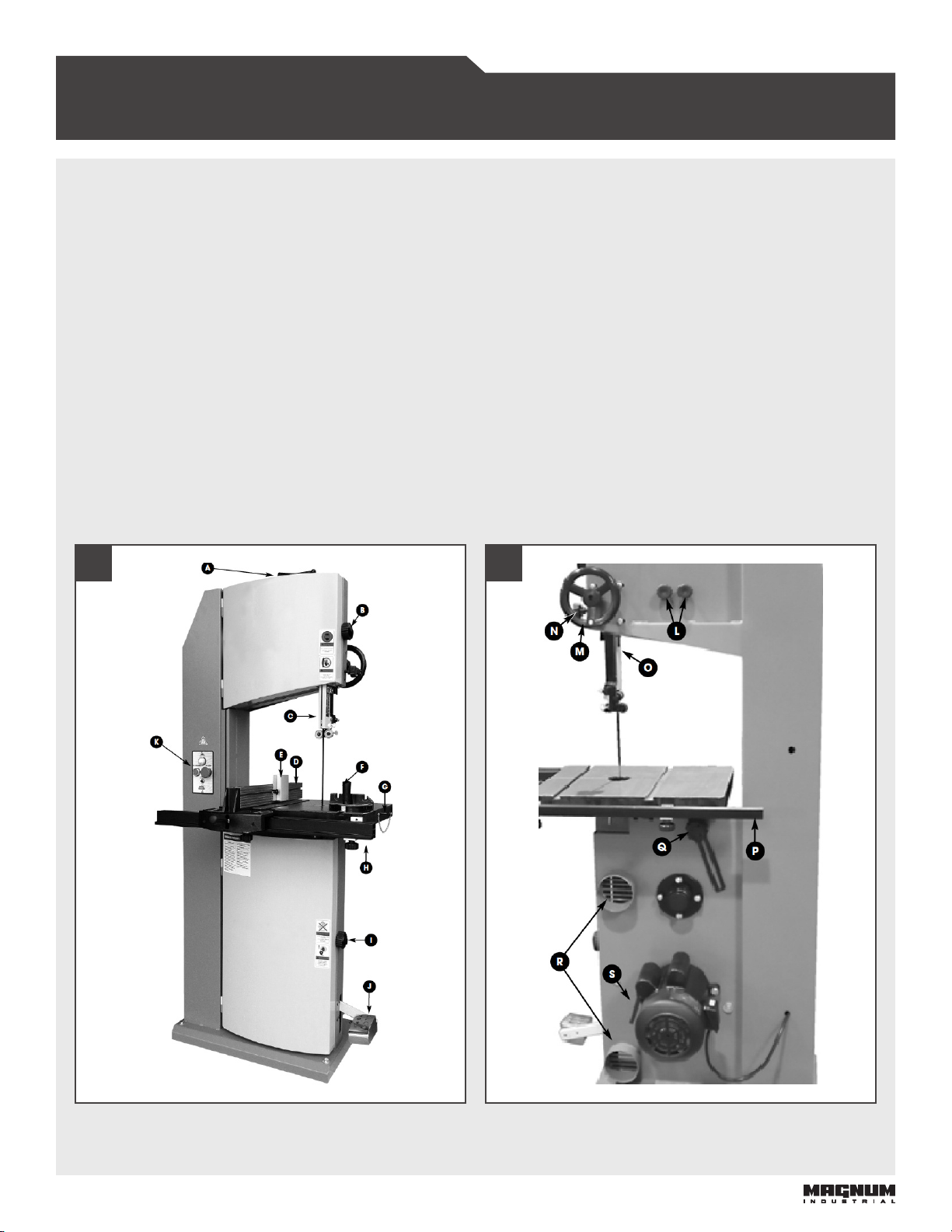
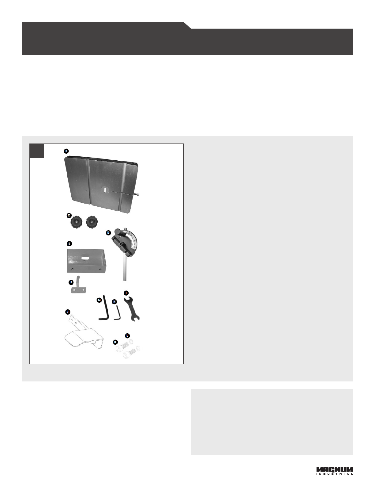
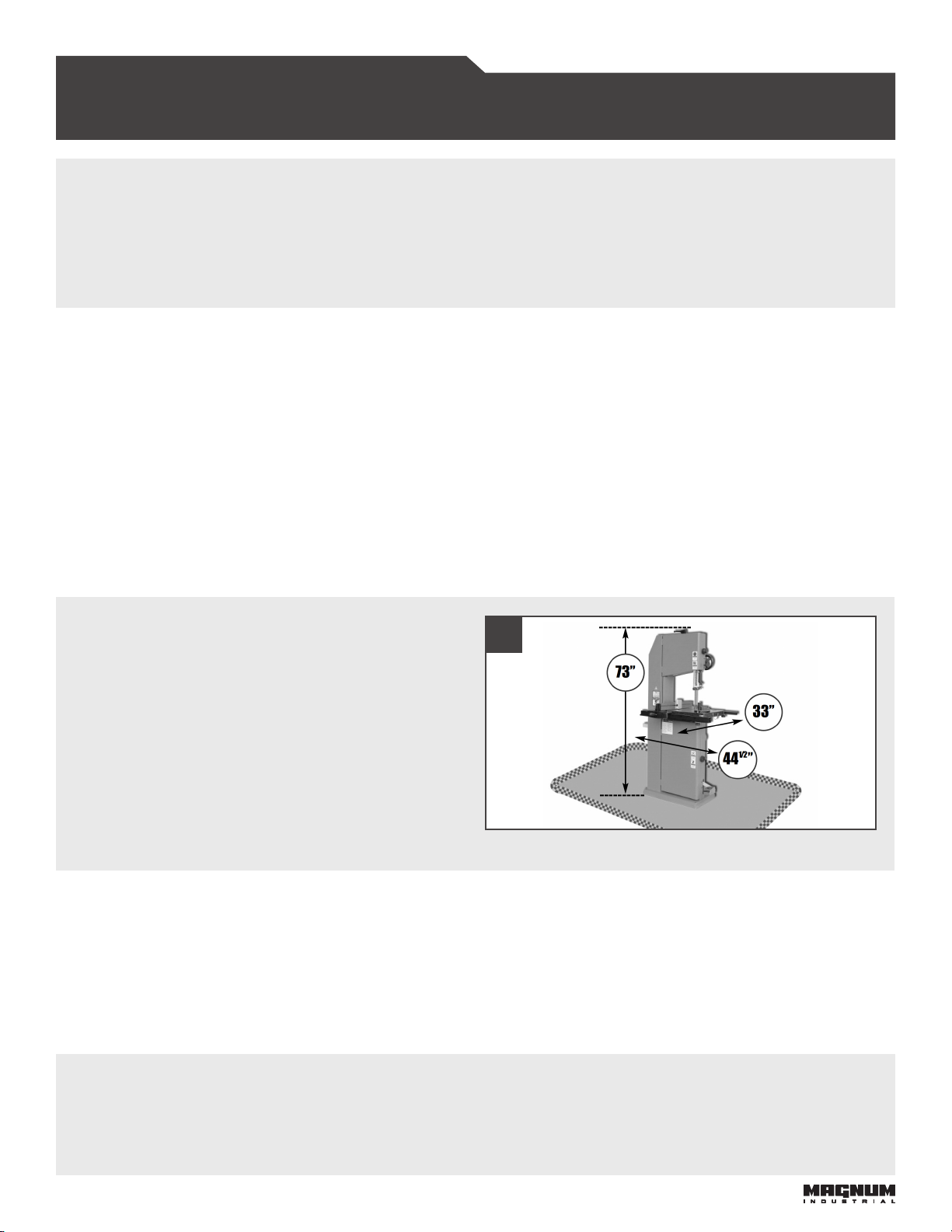
MAGNUM INDUSTRIAL MI-91500 DELUXE 14” BAND SAW
To help ensure safe operation, please take a moment to learn the how to operate the machine and understand its
applications and limitations, as well as potential hazards. KMS Tools and Equipment disclaims any real or implied warranty
and holds itself harmless for any injury that may result from the improper use of its equipment.
• Do not operate the band saw when tired, distracted or
under the effects of drugs, alcohol or any medication that
impairs reflexes or alertness.
• Ensure your working area is well lit and free of debris.
• Keep children and visitors at a safe distance when the
band saw is in operation. Do not permit them to operate
the band saw.
• Prevent unauthorized or unsupervised use by child
proofing and tamper proofing your shop and all machinery
with locks, master electrical switches and switch keys.
• Stay alert! Give your work your undivided attention. Even a
momentary distraction can lead to serious injury.
• Fine particulate dust is a carcinogen that can be hazardous
to health. Work in a well-ventilated area and whenever
possible use a dust collector. Wear face, eye, ear,
respiratory and body protection devices.
• Do not wear loose clothing, gloves, bracelets, necklaces or
other jewelry while the band saw is in operation.
• Remove adjusting wrenches, tools and other clutter
from the machine and the table surface before using the
machine.
• Keep hands well away from the blade and all moving parts.
Use a brush, not hands, to clear away chips and dust.
• Adjust and position upper and lower blade guides
before cutting. Upper blade guide should be adjusted to
approximately 1/8” above the material to be cut.
• Adjust blade tension and tracking before cutting.
• Saw teeth must point down toward the table.
• Be sure that the blade reaches full operating speed before
starting your cut.
• Always use a clean, properly sharpened blade. Dirty or dull
blades are unsafe and can lead to accidents.
• Use suitable workpiece support if the workpiece does not
have a at surface.
• Hold material rmly against the table.
• Do not work on long stock without adequate support on
the outfeed end of the table.
• If using a power feeder, stop the feeder before stopping
the band saw.
• Do not push or force stock into the blade. e band saw
will perform better and more safely when working at the
rate for which it was designed.
• Avoid working from awkward or o balance positions. Do
not overreach and keep both feet on oor.
• Keep guards in place and in working order. If a guard must
be removed for maintenance or cleaning, properly re-
attach it before using the tool again.
• Never leave the machine unattended while it is running or
with the power on.
•Never stand on machinery. Serious injury could result if the
tool is tipped over or if the cutting tool is unintentionally
contacted.
• Always disconnect the machine from the power source
before servicing or changing accessories such as blades, or
before performing any maintenance or cleaning, or if the
machine will be le unattended.
• Ensure the switch is in the OFF position before plugging in
the power cord.
• Make sure the tool is properly grounded. If equipped with
a three-prong plug it should be used with a three-pole
receptacle. Never remove the third prong.
• Do not use this band saw for other than its intended use.
If used for other purposes, KMS Tools and Equipment
disclaims any real or implied warranty and holds itself
harmless for any injury that may result from that use.