manuals.online logo
Brands
  1. Home
  2. •
  3. Brands
  4. •
  5. Beko
  6. •
  7. Dryer
  8. •
  9. Beko DRYPOINT M PLUS DM 08-19 K-N User guide

Beko DRYPOINT M PLUS DM 08-19 K-N User guide

DRYPOINT DM 08-19 K-N, 08-24 K-N, 08-28 K-N, 08-34 K-N 1
Sehr geehrter Kunde,
vielen Dank, daß Sie sich für DRYPOINT®M PLUS - Druckluft-Membrantrockner mit integriertem Filter entschieden haben.
Bitte lesen Sie vor Montage und Inbetriebnahme diese Installations- und Betriebsanleitung aufmerksam durch und befolgen Sie
unsere Hinweise. Nur bei Beachtung der Vorschriften und Hinweise ist eine einwandfreie Funktion des DRYPOINT®M PLUS
- Druckluft-Membrantrockners für eine hohe Druckluftqualität sichergestellt.
Dear Customer,
Thank you for deciding in favour of the DRYPOINT®M PLUS membrane dryer with integrated lter. Please read the present
instructions carefully before installing the DRYPOINT®M PLUS unit and putting it into service. The perfect functioning of the
DRYPOINT®M PLUS membrane dryer - and thus compressed-air quality of a high standard - can only be guaranteed if the
instructions and conditions stated here are complied with.
Cher client,
Vous venez d'acquérir un DRYPOINT®M PLUS avec ltre intégré et nous vous en félicitons. Nous vous recommandons de
lire attentivement ces instructions avant le montage et la mise en service et de suivre nos conseils. Car, seul le respect des
prescriptions et consignes données, peut garantir le parfait fonctionnement du sécheur à membrane DRYPOINT®M PLUS et
de ce fait, une haute qualité d'air comprimé.
Vážený zákazníku,
děkujeme, že jste se rozhodl pro pneumatickou membránovou sušičku se zabudovaným ltrem DRYPOINT®M PLUS. Ještě
předtím, než ji nainstalujete a uvedete do provozu, přečtěte si pozorně tento návod k instalaci a obsluze a respektujte naše
upozornění. Jen pokud budou dodržovány předpisy a upozornění, je zaručena bezchybná funkce pneumatické membránové
sušičky DRYPOINT®M PLUS pro zajištění vysoké kvality stlačeného vzduchu.
Installations- und Betriebsanleitung deutsch
Instructions for installation and operation english
Instructions de montage et de service français
Návod k instalaci a obsluze česky
DRYPOINT®M PLUS
Gehäuseversion mit integriertem Filter
Housing version with integrated lter
Version corps avec ltre intégré
Verze s krytem a zabudovaným ltrem
DM 08 - 19 K (A, B, C) - N
DM 08 - 24 K (A, B, C) - N
DM 08 - 28 K (A, B, C) - N
DM 08 - 34 K (A, B, C) - N
07-083
DRYPOINT DM 08-19 K-N, 08-24 K-N, 08-28 K-N, 08-34 K-N
2
Wichtige Hinweise • Important Notes
deutsch
1. Sachmängelhaftung
Bitte lesen Sie aufmerksam die nachfolgenden Hinweise.
Nur bei Beachtung dieser Hinweise und Einhaltung der Instal-
lationsanleitung kann eine Sachmängelhaftung übernommen
werden.
Beim Einsatz der vorgesehenen CLEARPOINT®-Filter und
einem jährlichen Tausch der Filterelemente besteht auf den
Druckluft-Membrantrockner ein Anspruch auf Beseitigung von
Sachmängeln innerhalb von 2 Jahren ab Rechnungsdatum.
BEKO TECHNOLOGIES GmbH haftet nicht für Schäden, die
durch unsachgemäße Behandlung, Abnutzung, Lagerung oder
sonstige Handlungen des Bestellers oder Dritter auftreten.
Dies gilt insbesondere für Verschleißteile.
2. Temperatur
Der Aufstellungsort muß frostfrei sein, die Temperaturen am
Aufstellungsort sowie der Druckluft müssen zwischen +2 und
+60 °C liegen.
3. Filter
Beachten Sie die Anforderung an Filter (siehe Seite 8 - 9):
Partikel, Ölanteile und üssiges Kondensat müssen sicher
zurückgehalten werden.
Hierzu ist ein CLEARPOINT®-Filter S (0,01 µm) im Gehäuse
des Membrantrockners integriert. Bei hoher Schmutzbelastung
oder starkem Kondensatanfall sind zusätzlich Feinstlter (0,01
µm) und ggf. Vorlter (5 µm) einzusetzen (siehe Seite 12).
Achtung: Die Filterelemente jährlich wechseln.
Achtung: Wartungsarbeiten nur am drucklosen Gerät durch-
führen !
Dazu gehört auch das Wechseln des im Membrantrockner
integrierten Filters :
- Gehäuseunterteil lösen (Feingewinde), dabei Gehäuseprol
des Membrantrockners festhalten
- Schwimmerableiter begutachten und ggf. auswechseln
(4006090)
- Filterelement austauschen und Gehäuse wieder festschrau-
ben
2
5
4
1
3
4
4
5
3 : integrierter Filter
integrated lter
5
5
5
5
8
DRYPOINT DM 08-19 K-N, 08-24 K-N, 08-28 K-N, 08-34 K-N 3
Wichtige Hinweise • Important Notes
english
1. Liability for defects
Please read this information very carefully:
Liability for defects can only be accepted if the following rules
and the instructions for installation are complied with.
Provided appropriate CLEARPOINT® lters are being used and
the lter elements are replaced once a year, the purchaser of
the compressed-air membrane dryer shall be entitled to claim
remedy of defects within 2 years from date of invoice.
BEKO TECHNOLOGIES GmbH shall not be liable for damage
due to improper or incorrect use, wear, storage or other actions
by the purchaser or third parties.
This applies in particular to wearing parts.
2. Temperature
There must be no danger of frost at the place of installation; the
temperatures at the place of installation and of the compressed
air should be between +2 and + 60 °C.
3. Filters
Please observe the relevant lter requirements (see page
8 - 9):
Dirt particles, oil residues and liquid condensate have to be
safely retained.
For these purposes a CLEARPOINT® lter S (0,01µ) is inte-
grated in the membrane dryer housing. With high dirt loads or
large amounts of condensate, it will be necessary to install a
super ne lter (0,01 µm) in addition and, where appropriate,
a pre lter (5 µm) (see page 12).
Caution: The lter elements need to be replaced once a
year.
Caution: maintenance works must be carried out only when
the device is pressureless!
This applies for the replacement of the lter as well which is
an integrated part of the membrane dryer:
- Remove bottom part of the membrane dryer housing (ne
thread). In doing so hold the upper part tight in its posi-
tion.
- check the oat drain and replace it, if required (4006090)
- Exchange the lterelement and reassemble the two body
parts and screw tight
4. Shuto󰀨 units
The shuto󰀨 elements must not be opened suddenly. It is rec-
ommended to install a bypass around the unit.
5. Installation/putting into service
Clean the pipes thoroughly (e.g., by blowing through them)
before installing the membrane dryer.
Observe the installation direction of lters and membrane dryer
(see marking indicating the direction of ow on the heads).
6. Mounting of DRYPOINT®M PLUS
Wall brackets are available as accessories. Ensure that
replacement of the lter elements cannot damage the mem-
brane dryer.
7. Sealing material
Note: Use Teon tape to seal o󰀨 all threaded connections
upstream of the DRYPOINT®M PLUS membrane dryer and
on the device itself. Do not use any liquid sealants.
8. Purge air
The purge air must be able to ow freely out of the orices.
9. Place of installation
The room of installation, plants and equipments in this room,
or stored materials must not release chemically active materi-
als.
4. Absperreinheiten
Absperrelemente nicht schlagartig ö󰀨nen.
Eine Bypassleitung um die Einheit wird empfohlen.
5. Montage/Inbetriebnahme
Vor Einbau des Membrantrockners Leitungen gründlich reini-
gen (z.B. durch Ausblasen).
Einbaurichtung von Filtern und Membrantrockner beachten
(vgl. Kennzeichnung der Durchussrichtung auf den Köp-
fen).
6. Befestigung DRYPOINT®M PLUS
Wandhalter können als Zubehör bestellt werden. Die Befesti-
gung so anbringen, dass beim Wechsel der Filterelemente kei-
ne Beschädigungen am Membrantrockner auftreten können.
7. Dichtmittel
Achtung: Alle Gewinde vor und am DRYPOINT®M PLUS-
Druckluft-Membrantrockner mit Teonband eindichten. Keine
üssigen Dichtmittel benutzen.
8. Spülluft
Die Spülluft muss ungehindert aus den Bohrungen austreten
können.
9. Installationsort
Aufstellungsraum bzw. darin enthalten Anlagen und Ausrü-
stungen oder gelagerte Materialien dürfen nicht chemisch
aktive Sto󰀨e freisetzen.
DRYPOINT DM 08-19 K-N, 08-24 K-N, 08-28 K-N, 08-34 K-N
4
Remarques importantes • Důležitá upozornění
français
Responsabilité du fait des produits défectueux
Veuillez lire attentivement les consignes suivantes.
La responsabilité du fait des produits défectueux n’est engagée
que si ces consignes et instructions de montage et de service
sont respectées.
Si les ltres CLEARPOINT® préconisés sont utilisés, et si les
éléments ltrants sont remplacés une fois par an, le sécheur
d’air comprimé à membrane bénécie d’une garantie d’élimi-
nation des vices pendant une période de 2 ans, à compter de
la date de facturation.
BEKO TECHNOLOGIES GmbH n’engage pas sa respon-
sabilité pour les dégâts occasionnés par une utilisation non
conforme, par l’usure, par le stockage ou par d’autres mani-
pulations e󰀨ectuées par le donneur d’ordre ou un tiers.
Ceci est valable en particulier pour les pièces d’usure.
2. Température
Le lieu d'installation doit être à l'abri du gel, les températures
ambiantes ainsi que celle de l'air comprimé doivent être com-
prises entre +2 et +60 °C.
3. Filtre
Respectez les exigences relatives au choix du ltre (voir
page 8 - 9) :
Les particules solides, les particules d'huile et le condensat
liquide doivent être retenus en toute abilité.
Pour ce faire, un ltre CLEARPOINT® S(0,01 µm) est inté-
gré dans le corps du sécheur à membrane. En cas de fortes
concentrations en impuretés et de production importante de
condensat, il faut utiliser en plus un ltre submicronique (0,01
µm) et le cas échéant un préltre (5 µm) (voir pagina 12).
Attention : Les éléments ltrants doivent être remplacés une
fois par an.
Attention : Les travaux de maintenance ne doivent être e󰀨ec-
tués que lorsque l´appareil se trouve hors pression !
En fait également partie, le remplacement du ltre intégré
dans le sécheur à membrane :
- Desserrer la partie inférieure du corps (letage n) ; pour ce
faire, maintenir le prolé du sécheur à membrane
- Vérier l’état du purgeur à otteur et au besoin, le remplacer
(4006090).
- Remplacer l’élément ltrant et resserrer le corps
3: Filtre intégré
zabudovaný ltr
2
5
4
1
3
4
4
5
5
5
5
5
8
DRYPOINT DM 08-19 K-N, 08-24 K-N, 08-28 K-N, 08-34 K-N 5
Remarques importantes • Důležitá upozornění
4. Vannes d'arrêt
Ne pas ouvrir brusquement les vannes d'arrêt.
La mise en place d'une conduite bypass est recommandée.
5. Installation / mise en service
Avant d'installer le sécheur à membrane, nettoyer soigneuse-
ment les conduites (par ex., les sou󰀪er à l'air comprimé).
Respecter le sens de montage des ltres et du sécheur à
membrane (le sens de circulation est indiqué sur l'enveloppe
têtes).
6. Fixation du DRYPOINT®M PLUS
Les consoles murales ne sont disponibles en tant qu' accesoi-
res. Mettre en œuvre la xation de telle sorte que le sécheur
ne risque pas d'être endommagé lors du remplacement des
éléments ltrants.
7. Étanchéité
Attention : pour assurer l'étanchéité de tous les letages,
avant et sur le sécheur à membrane DRYPOINT®M PLUS,
utiliser du ruban de téon. N'utiliser aucun produit d'étan-
chéité liquide.
8. Air de balayage
L‘air de balayage doit pouvoir s‘échapper librement des trous
de perçage.
9. Lieu de l´installation
La pièce où est placée l´appareil à savoir les installations ou
équipements pouvant s´y trouver ou les matières pouvant y
être entreposées ne doivent libérer aucune substance chimi-
quement active.
čeština
1. Ručení za věcné vady
Přečtěte si pozorně níže uvedená upozornění.
Ručení za věcné vady můžeme převzít jen za předpokladu, že
jsou respektována tato upozornění a dodržován tento návod
k instalaci.
Při použití určeného ltru CLEARPOINT® a každoroční výmě-
ně ltračních vložek existuje na pneumatickou membránovou
sušičku nárok na odstranění věcných vad po dobu dvou let od
data vystavení faktury.
BEKO TECHNOLOGIES GmbH neručí za škody, které vznik-
nou neodbornou manipulací, opotřebením, skladováním nebo
dalším konáním objednavatele nebo třetích osob.
To se týká zejména dílů podléhajících rychlému opotřebení.
2. Teplota
Na místě instalace nesmí docházet k zamrzání, teplota v místě
instalace a teplota stlačeného vzduchu se musí pohybovat v
rozmezí od +2 do +60 °C.
3. Filtr
Dodržujte požadavky na ltr (viz strana 8 – 9):
Zachycování částic, částí oleje a tekutého kondenzátu musí
probíhat bezpečně.
Kvůli tomu je v krytu membránové sušičky zabudován ltr
CLEARPOINT® S (0,01 µm). Při vysokém hromadění nečistot
nebo silné tvorbě kondenzátu je třeba použít navíc jemný ltr
(0,01 µm) a popř. předřazený ltr (5 µm) (viz strana 12).
Pozor: Filtrační vložky vyměňujte jednou za rok.
Pozor: Údržba přístroje se musí provádět jen ve chvíli, kdy
není přístroj pod tlakem!
Do údržby patří též výměna ltru zabudovaného v membrá-
nové sušičce:
- uvolněte spodní díl krytu (jemný závit), přitom pevně přidr-
žujte prol krytu membránové sušičky
- zkontrolujte plovákový odvaděč a popř. jej vyměňte
(4006090)
- vyměňte ltrační vložku a kryt zase pevně přišroubujte
4. Uzavírací jednotky
Uzavírací prvky neotvírejte prudce.
Doporučujeme použít obtokové vedení kolem jednotky.
5. Montáž / uvedení do provozu
Před montáží membránové sušičky důkladně vyčistěte potrubí
(např. jeho profouknutím).
Dodržte směr namontování ltrů a membránové sušičky (srov.
symbol směru průtoku na hlavicích).
6. Upevnění přístroje DRYPOINT®M PLUS
Nástěnné držáky lze objednávat jako příslušenství. Upevnění
udělejte tak, aby při výměně ltračních vložek nemohlo dojít k
poškození membránové sušičky.
7. Těsnicí prostředky
Pozor: Všechny závity před pneumatickou membránovou
sušičkou DRYPOINT®M PLUS a na této sušičce utěsněte teo-
novou páskou. Zákaz použití tekutých těsnicích prostředků.
8. Profukovací vzduch
Profukovací vzduch musí volně proudit z otvorů.
9. Místo instalace
Místo instalace, resp. v něm se nacházející zařízení a vyba-
vení či uskladněné materiály nesmějí uvolňovat chemicky
aktivní látky.
DRYPOINT DM 08-19 K-N, 08-24 K-N, 08-28 K-N, 08-34 K-N
6
Funktion • Function • Fonctionnement • Funkce
deutsch
Aufbau des Membrantrockners
A : Kopf (Eingang / Ausgang)
B : Gehäuse / Filtergehäuse
C: Filter mit Abstützung
D: Membranelement mit Kernrohr
E : Düse mit Adapter
F: Schwimmerableiter 4006090
Funktion
(1) Feuchte Druckluft tritt durch den Kopf
(A) ein und strömt durch das Kernrohr
des Membranelements (D) nach unten.
(2) Im Austritt des Kernrohres ist ein
Filter (C) xiert, der die Druckluft von
restlichen Aerosolen und Partikeln be-
freit. Abgeschiedenes Kondensat ießt
am Boden ab.
Im Bereich des Filterelementes wird
die Strömungsrichtung gedreht und
die feuchte Druckluft durchströmt die
Membranen des Membranelements (D)
innen.
(3) Nach dem Membranelement wird
kontinuierlich ein Teilstrom der Druck-
luft abgezweigt und an einer Düse (E)
atmosphärisch entspannt.
Durch die Entspannung wird diese Spül-
luft wesentlich trockener, da sich die in
der Druckluft enthaltene Feuchte auf ein
Vielfaches des ehemaligen Volumens
verteilt.
(4) Diese sehr trockene Spülluft wird im
Membranelement (D) über die Aussen-
seite der Membranen geführt und durch
die geordnete Lage der Membranen sehr
gleichmäßig verteilt.
(5) Dadurch bewegen sich – nur ge-
trennt durch die Membranwandung
– zwei Luftströme mit unterschiedlichem
Feuchtegehalt im Gegenstrom durch das
Membranelement :
Innen die feuchte Druckluft, aussen die
trockene Spülluft. Aufgrund des Feuch-
teunterschiedes di󰀨undiert Feuchtigkeit
aus der Druckluft in die Spülluft.
(6) Die Druckluft tritt getrocknet aus
dem DRYPOINT®M PLUS Druckluft-
Membrantrockner aus.
(7) Die feuchte Spülluft gelangt in die
Umgebung.
A
5
2
4
3
6
C
D
B
E
1
7
B
F
DRYPOINT DM 08-19 K-N, 08-24 K-N, 08-28 K-N, 08-34 K-N 7
Funktion • Function • Fonctionnement • Funkce
English
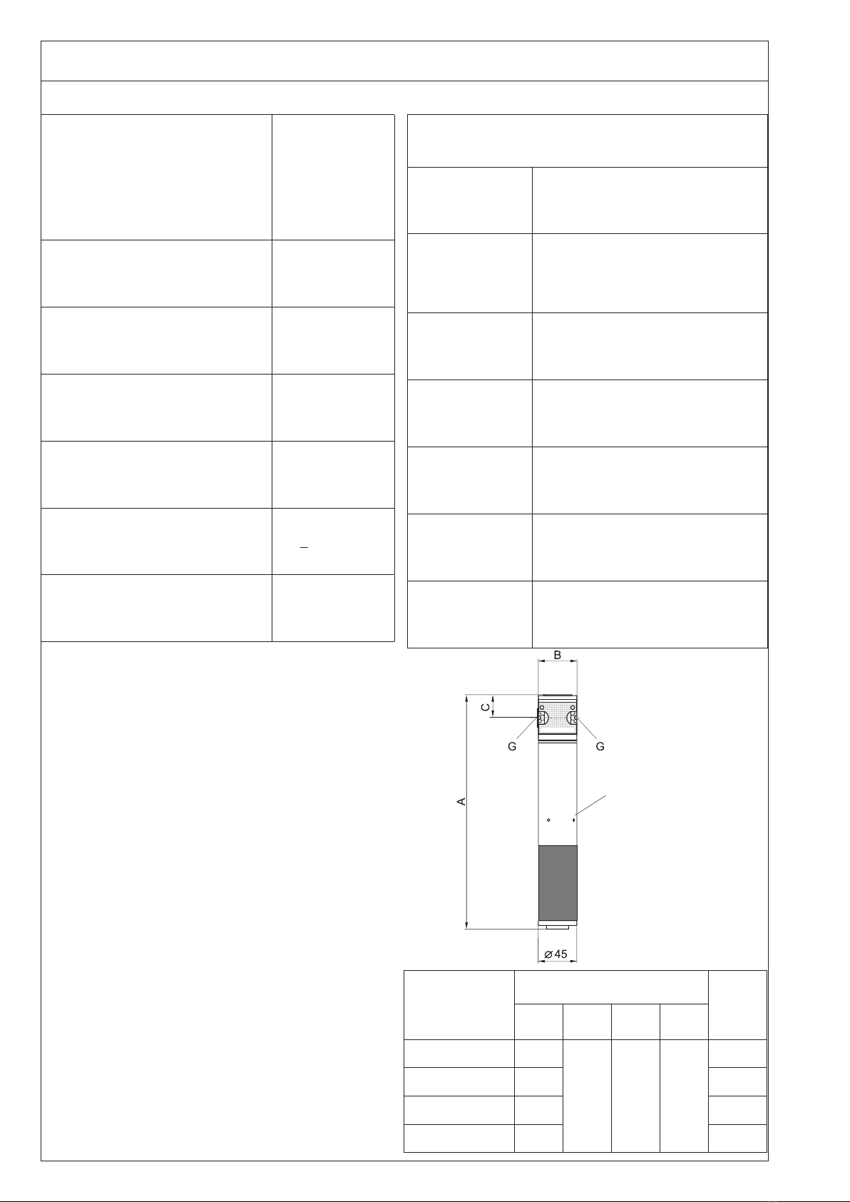
Membrane dryer layout
A : Head (inlet/outlet)
B : Housing / Filter housing
C : Filter with support
D: Membrane element with core tube
E : Nozzle with adapter
F : oat drain 4006090
Function
(1) Moist compressed air enters through
the head (A) and flows downwards
through the core tube of the membrane
element (D).
(2) The outlet of the core tube is con-
nected to a lter (C) which separates
the compressed air from aerosoles and
particulate matter. Separated condensate
uid is discharged from the bottom.
In the area of the lter element, the di-
rection of ow is reversed and the moist
compressed air then ows through the
membranes of the inner membrane ele-
ment (D).
(3) At the end of the membrane element
a partial ow of compressed air is con-
tinuously diverted and atmospherically
expanded through a nozzle (E).
Due to the expansion, the diverted air –
referred to as purge air – becomes much
drier because the moisture contained in
the compressed air is now distributed
over a much greater volume.
(4) This extremely dry purge air is chan-
nelled through the membrane element
(D) along the outside of the membranes.
Due to the ordered structure of the
membranes, the purge air is very evenly
distributed.
(5) Consequently, two ows of air with
different humidity levels move in a
countercurrent direction through the
membrane element, separated only by
the membrane wall:
inside the moist compressed air, outside
the dry purge air. As a result of the humid-
ity di󰀨erence, moisture di󰀨uses from the
compressed air into the purge air.
(6) Dry compressed air ows out of the
DRYPOINT®M PLUS membrane dryer.
(7) Moist purge air is discharged into the
environment.
français
Constitution du sécheur à membrane
A : Tête (entrée/sortie)
B : Corps / corps de ltre
C : Filtre avec appui
D: Élément de membranes avec
tube support
E : Buse avec adapteur
F: Purgeur à otteur 4006090
Fonctionnement
(1) L’air comprimé humide entre par la
tête (A) et circule à travers le tube support
de l’élément de membranes (D), du haut
vers le bas.
(2) A la sortie du tube support est xé
un ltre (C), qui libère l’air comprimé
des aérosols et particules résiduels. Le
condensat séparé s’écoule par le fond.
Dans la zone du ltre, le sens de circula-
tion est inversé et l’air comprimé humide
circule à l’intérieur des membranes de
l’élément (D).
(3) Après l'élément à membranes, une
partie du ux d'air comprimé est prélevée
en continu puis détendue à la pression
atmosphérique par une buse (E).
Suite à la détente, cet air de balayage
devient beaucoup plus sec, étant donné
que l'humidité contenue dans l'air com-
primé se répand dans un multiple du
volume initial.
(4) Cet air de balayage très sec circule
au sein de l'élément à membranes (D)
le long de la face extérieure des mem-
branes et du fait de la position ordonnée
des membranes, ce ux d'air est réparti
de façon homogène.
(5) C'est ainsi que circulent à contre-
courant à travers l'élément à membranes
deux ux d'air d'un taux d'humidité di󰀨é-
rent - séparés uniquement par la paroi
des membranes.
A l'intérieur, l'air comprimé humide, à
l'extérieur, l'air de balayage sec. La di󰀨é-
rence d'humidité provoque une di󰀨usion
continue de la vapeur d'eau de l'air com-
primé vers l'air de balayage.
(6) L'air comprimé sort du sécheur à mem-
brane DRYPOINT®M PLUS à l'état sec.
(7) L'air de balayage humide est refoulé
dans l'atmosphère.
čeština
Konstrukce membránové sušičky
A : Hlavice (vstup / výstup)
B : Kryt / kryt ltru
C : Filtr s vyztužením
D : Membránové vlákno s jádrovou trub-
kou
E : Tryska s adaptérem
F : Plovákový odvaděč 4006090
Funkce
(1) Vlhký stlačený vzduch vstupuje hlavicí
(A) a proudí jádrovou trubkou membrá-
nového vlákna (D) dolů.
(2) Na výstupu jádrové trubky je při-
pevněn ltr (C), který zbavuje stlačený
vzduch zbytkových aerosolů a částic.
Odloučený kondenzát odtéká na dno.
V oblasti ltrační vložky se směr proudě-
ní otáčí a vlhký stlačený vzduch proudí
uvnitř skrz membrány membránového
vlákna (D).
(3) Za membránovým vláknem se dílčí
proud stlačeného vzduchu nepřetržitě
rozděluje a uvolňuje na jedné trysce (E)
do atmosféry.
Tento profukovací vzduch je díky uvolnění
výrazně sušší, protože vlhkost obsažená
ve stlačeném vzduchu se rozloží na ně-
kolikanásobek původního objemu.
(4) Tento velice suchý profukovací vzduch
je v membránovém vláknu (D) veden
po vnější straně membrán a velice rov-
noměrně distribuován díky pravidelně
uloženým membránám.
(5) Membránovým vláknem se tak proti
sobě pohybují dva proudy vzduchu s
rozdílným obsahem vlhkosti oddělené
pouze stěnou membrány:
Uvnitř proudí vlhký stlačený vzduch, vně
pak suchý profukovací vzduch. Z důvodu
rozdílné vlhkosti dochází k difúzi vlhkosti
ze stlačeného vzduchu do profukovacího
vzduchu.
(6) Z pneumatické membránové sušičky
DRYPOINT®M PLUS vystupuje vysuše-
ný stlačený vzduch.
(7) Vlhký profukovací vzduch je odváděn
do okolí.
DRYPOINT DM 08-19 K-N, 08-24 K-N, 08-28 K-N, 08-34 K-N
8
Filtration • Filtration • Filtration • Filtrace
ölgeschmiert / oil lubricated
lubrié à l'huile / namazaný olejem
ölfrei / oilfree
non huileux / bez oleje
hinter Kessel
downstream of receiver
en aval de la cuve
za kotlem
hinter Kältetrockner
downstream of refridgerated dryer
en aval du sécheur frigorique
za sušičkou pro vysoušení za
studena
Filter
S
(inte-
gr.)
Filter
0,01
µm
Vorl-
ter
5 µm
ölgeschmiert
oil lubricated
lubrié à l'huile
namazaný olejem
ölfrei / oilfree
non huileux / bez oleje
ölgeschmiert / oil lubricated
lubrié à l'huile / namazaný
olejem
ölfrei / oilfree
non huileux / bez oleje
direkt hinter Kompressor
directly downstream of compressor
directement en aval du compresseur
hned za kompresorem
DRYPOINT DM 08-19 K-N, 08-24 K-N, 08-28 K-N, 08-34 K-N 9
Filtration • Filtration • Filtration • Filtrace
deutsch
Eine e󰀨ektive Partikel- und Kondensatabscheidung sowie
eine bestmögliche Ölabscheidung vor dem Membrantrockner
sind Grundvoraussetzung für eine sichere Funktion und eine
lange Standzeit.
Für die Ölabscheidung ist immer ein Feinstlter 0,01 µm er-
forderlich (im Membrantrockner integriert).
Grundanforderungen an die Druckluft für Eintritt in den
Membrantrockner :
- kein Kondensat
- keine Partikel größer 1 µm
- Ölgehalt max. 0,01 mg/m³
Beachten Sie bitte die nachfolgend schematisch dargestellten
Empfehlungen und Vorgaben für Hauptanwendungen zu den
Filtrationsstufen vor dem Membrantrockner.
Achtung: Wartungsarbeiten nur am drucklosen Gerät durch-
führen !
Wechsel des integrierten Filterelements :
- Gehäuseunterteil lösen (Feingewinde), dabei Gehäuse des
Membrantrockners festhalten
- Schwimmerableiter begutachten und ggf. auswechseln
(4006090)
- Filterelement austauschen und Gehäuse wieder festschrau-
ben
english
Effective particle and condensate separation as well as
optimum oil removal upstream of the membrane dryer are
fundamental requirements for the reliable operation and long
lifetime of the unit.
For oil separation an 0.01 mm super ne lter needs to be
installed (integrated in the membran dryer).
Basic specifications for compressed-air entering the
membrane dryer:
- Free of condensate
- No particles larger than 1 mm
- Residual oil content max. 0.01 mg/m³
It is essential to observe the recommendations and speci-
cations for the ltration stages upstream of the membrane
dryer, as set out here schematically in relation to the main
applications.
Caution: maintenance works must be carried out only when
the device is pressureless!
Replace of the integrated lter:
- Remove bottom part of the membrane dryer housing (ne
thread). In doing so hold the upper part tight in its posi-
tion.
- check the oat drain and replace it, if required (4006090)
- Exchange the lterelement and reassemble the two body
parts and screw tight
français
La condition requise pour un fonctionnement able et une
longue durée de vie des membranes est la présence en
amont du sécheur, d'une séparation e󰀩cace des particules,
des condensats et de l'huile en suspension.
Un ltre submicronique 0,01 µm est toujours requis pour la
séparation de l'huile (intégré dans le sécheur à membrane).
Exigences fondamentales pour que l'air comprimé puisse
entrer dans le sécheur à membrane :
- pas de condensat
- pas de particules supérieures à 1 µm
- teneur en huile max. 0,01 mg/m³
Tenez compte des recommandations et indications représen-
tées sous forme graphique ci-dessous et relatives aux di󰀨érents
étages de ltration en amont du sécheur à membrane.
Attention : Les travaux de maintenance ne doivent être e󰀨ec-
tués que lorsque l´appareil se trouve hors pression !
Remplacement de l’élément ltrant du ltre intégré:
- Desserrer la partie inférieure du corps (letage n) ; pour ce
faire, maintenir le prolé du sécheur à membrane
- Vlotterafscheider controleren en eventueel vervangen
(4006090)
- Remplacer l’élément ltrant et resserrer le corps
čeština
Základní podmínkou bezpečné funkce a dlouhé životnosti
sušičky je efektivní odlučování částic a kondenzátu a optimální
odlučování oleje před membránovou sušičkou.
Pro odlučování oleje je vždy nutný jemný ltr 0,01 µm (zabu-
dovaný v membránové sušičce).
Základní požadavky na stlačený vzduch pro vstup do
membránové sušičky:
- žádný kondenzát
- žádné částice větší než 1 µm
- obsah oleje max. 0,01 mg/m³
Respektujte níže uvedená schématicky znázorněná doporučení
a dodržujte stanovené hodnoty pro hlavní použití ltračních
stupňů před membránovou sušičkou.
Pozor: Údržba přístroje se musí provádět jen ve chvíli, kdy
není přístroj pod tlakem!
Výměna zabudované ltrační vložky:
- uvolněte spodní díl krytu (jemný závit), přitom pevně přidr-
žujte kryt membránové sušičky
- zkontrolujte plovákový odvaděč a popř. jej vyměňte
(4006090)
- vyměňte ltrační vložku a kryt zase pevně přišroubujte
DRYPOINT DM 08-19 K-N, 08-24 K-N, 08-28 K-N, 08-34 K-N
10
Technische Daten • Technical Data
Caractéristiques Techniques • Technické parametry
1) Version mit Montageverguss (-AP) bis 16 bar / 70 °C
Version with assembly potting (-AP) up to 16 bar / 70 °C
Version moulée (-AP) jusqu’à 16 bar / 70°C
verze s montážním kompaundem (-AP) do 16 bar / 70 °C
2) bei anderen Bedingungen bitte anfragen
with di󰀨erent conditions, please request
si les conditions di󰀨èrent, consulter le constructeur
v případě jiných podmínek nás kontaktujte
3) abhängig von der Druckluftdurchußmenge
depending on compressed-air throughput
dépend du débit d'air comprimé
závislé na množství protékajícího stlačeného vzduchu
4) Ölgehalt < 0,01 mg/m³ bei 20 °C
oil content < 0.01 mg/m³ at 20 °C
teneur en huile < 0,01 mg/m³ à 20° C
obsah oleje < 0,01 mg/m³ při 20 °C
Spülluftausgang
Purge air outlet
Sortie de l'air de balayag
Výstup profukovacího
vzduchu
Druckbereich / Temperatur Druckluft 1)
Pressure range / Compressed-air
temperature
Plage de pression / Température air
comprimé
Rozsah tlaku / teplota stlačeného
vzduchu
4...12,5 bar / +50 °C
4...7 bar / +60 °C
Umgebungstemperatur 2)
Ambient temperature
Température ambiante
Okolní teplota
+2 ... +60 °C
Druckverlust 3)
Pressure loss
Perte de charge
Pokles tlaku
0,1 ... 0,3 bar
Vorlter 4)
Prelter
Pré ltre
Předřazený ltr
1 µm
Feinstlter, integriert 4)
super ne lter, integrated
ltre submiquronicue, intégré
Jemný ltr, zabudovaný
0,01 µm
Geräuschpegel
Noise level
Niveau sonore
Hladina hluku
< 45 dB (A)
Einbaulage
Installation position
Position de montage
Montážní poloha
senkrecht
vertical
vertical
svislá
Werksto󰀨e / Materials / Matériaux / Materiály
Membran
Membrane
Membrane
Membrána
Polyethersulfon
Polyether sulphone
Polyéthersulfone
Polyethersulfon
Vergussmaterial
Cast material
Pièces moulées
Kompaundový
materiál
Polyurethan
Polyurethane
Polyuréthane
Polyuretan
Filterkopf
Filter head
Tête du ltre
Filtrační hlavice
Zingdruckguss
Zinc die casting
Zinc moulé sous pression
Tlakový zinkový odlitek
Gehäuse
Housing
Corps
Kryt
Aluminium, eloxiert
Aluminium, anodized
Aluminium, anodisé
Hliník, eloxovaný
Kernrohr
Core tube
Tube support
Jádrová trubice
Aluminium, seewasserbeständig
Aluminium, seawater-resistant
Aluminium, résistant aux milieux salins
Hliník, odolný vůči mořské vodě
Düse
Nozzle
Buse
Tryska
Messing
Brass
Laiton
Mosaz
O-Ringe
O ring
Joint torique
O-kroužky
NBR
Baugröße
Size
Modèle
Velikost konstrukce
Abmessungen / Dimensions
Dimensions / Rozměry Gewicht
Weight
Poids
Hmotnost
A
mm
D
mm
SW
mm
G
Zoll
DM 08 - 19 K-N 265
46 27 ¼"
0,79
DM 08 - 24 K-N 315 0,87
DM 08 - 28 K-N 355 0,94
DM 08 - 34 K-N 415 1,03
DRYPOINT DM 08-19 K-N, 08-24 K-N, 08-28 K-N, 08-34 K-N 11
Leistungsangaben • Performance data
Capacités nominales • Výkonové parametry
Beispiel für eine Drucktaupunktabsenkung von 35 °C auf 3 °C, DM 08 - 19 K-N, Typ B :
Eingangsvolumenstrom: 35 l/min (bei 7 bar)
Leistung bei 5 bar: 35 l/min x 0,56 = 19,6 l/min
Example of pressure dew point suppression from 35 °C to 3 °C, DM 08 - 19 K-N, Type B :
Inlet volumetric ow: 35 l/min (at 7 bar)
Performance at 5 bar: 35 l/min x 0.56 = 19,6 l/min
Exemple de calcul pour un abaissement du PRSP de 35 °C à 3 °C, DM 08 - 19 K-N, Modèle B :
Débit d'entrée: 35 l/min (à 7 bar)
Capacité à 5 bar: 35 l/min x 0,56 = 19,6 l/min
Příklad poklesu tlakového rosného bodu z 35 °C na 3 °C, DM 08 - 19 K-N, typ B:
Vstupní objemový průtok: 35 l/min (při 7 bar)
Výkon při 5 bar: 35 l/min x 0,56 = 19,6 l/min
Typ
Type
Modèle
Typ
Spülluft
Purge air
Air de
balayage
Profuko-
vací
5)
l/min
7 bar, Drucktaupunktabsenkung von 35 °C auf
7 bar, pressure dew point suppression from 35 °C to
7 bar, abaissement du PRSP de 35 °C à
7 bar, pokles tlakového rosného bodu z 35 °C na
15 °C 6)3 °C 6)-10 °C 6)-20 °C 6)
Ein
In
Aus
Out
Ein
In
Aus
Out
Ein
In
Aus
Out
Ein
In
Aus
Out
DM 08 - 19 K-N
A5 50 45 32 27 23 18 19 14
B 3 31 28 21 18 15 12 12 9
C 3 -- -- 21 18 15 12 12 9
DM 08 - 24 K-N
A 10 100 90 66 56 49 39 42 32
B5 51 46 35 30 27 22 24 19
C5-- -- 35 30 27 22 24 19
DM 08 - 28 K-N
A15 150 135 100 85 74 59 63 48
B 10 102 92 70 60 55 45 48 38
C7 74 67 52 45 40 33 35 28
DM 08 - 34 K-N
A 20 200 180 133 113 99 79 84 64
B15 153 138 105 90 82 67 72 57
C 10 106 96 74 64 57 47 50 40
7)
Die Leistungsdaten und Drucktaupunktabsenkungen beziehen
sich auf einen Eintrittsdrucktaupunkt der Druckluft von +35
°C und einen Druck von 7 bar.
The performance data and the lowering of the pressure dew
point (PDP) relate to compressed air with an inlet pressure
dew point of +35 °C and a pressure of 7 bar.
Les capacités et les abaissement du point de rosée se rappor-
tent à un point de rosée sous pression à l'entrée de l'air
comprimé de +35 °C et à une pression de 7 bar.
Výkonové parametry a pokles tlakového rosného bodu se
vztahují na vstupní tlakový rosný bod stlačeného vzduchu
+35 °C a tlak 7 bar.
5) Toleranz Spülluftmenge :
+3 % bezogen auf max. Eingangs - Volumenstrom
Purge-air supply tolerance :
+3 % related to max. volumetric ow at inlet
Tolérances Débit d'air de balayage :
+3 % par rapport au débit d'air maximal à l'entrée
tolerance množství profukovacího vzduchu:
+3 % vztaženo na max. vstupní objemový průtok
6) Toleranz Drucktaupunkt : +3 K
Pressure dew point tolerance : +3 K
Tolérances Point de rosée sous pression : +3 K
Toleranz Drucktaupunkt : +3 K
7) Volumenstrom bei Betriebsüberdruck 7 bar,
bezogen auf 20 °C und 1bar absolut
Volumetric ow at 7 bar operating pressure,
related to 20 °C and 1 bar absolute
Débit pour une pression de service de 7 bar,
reletif à 20 °C et 1 bar, absolu.
objemový průtok při navýšeném provozním tlaku 7 bar,
vztaženo na 20 °C a 1 bar absolutní
Bei abweichenden Betriebsdrücken von 7 bar sind nachfolgende Korrekturfaktoren für den Volumenstrom einzusetzen :
With operating pressures other than 7 bar, the following correction factors should be used for the volumetric ow :
Lorsque la pression de service diverge de la pression nominale de 7 bar, il faut multiplier le débit par les facteurs de correction
suivants :
Při odlišných hodnotách provozního tlaku než 7 bar je nutné použít opravné faktory pro objemový průtok:
Druck/Pressure/Pression/Tlak (bar) 4 5678 9 10 11 12
Faktor/Factor/Facteur/Faktor 0,39 0,56 0,77 1 1,19 1,4 1,61 1,84 2,07
DRYPOINT DM 08-19 K-N, 08-24 K-N, 08-28 K-N, 08-34 K-N
12
Zubehör • Assessories • Accessores • Příslušenství
0,35
0,45
Bestell-Nr. • order ref.
No de com. • Obj.
Gewicht / Weight
Poids / váha
4011323
4005810
4008652
Vorlter mit Schwimmerableiter und Koppelpaket 5 µm
Pre lter with ball oat trap including coupling packet
Préltre micronique avec purgeur à otteur et kit d’accouplement
Předřazený ltr s plovákovým odvaděčem a spojovacím ma-
teriálem
Druckregler
Pressure regulator
Régulateur de pression
Tlakový ventil
Wandhalter
Wall bracket
Console murale
Nástěnný držák
Feinstlter mit Schwimmerableiter und Koppelpaket 0,01 µm
Super ne lter with ball oat trap including coupling packet
Filtre submicronique avec purgeur à otteur et kit d’accouplement
Jemný ltr s plovákovým odvaděčem a spojovacím materiálem
Aktivkohlelter mit Koppelpaket
Activated carbon lter with coupling packet
Filtre à charbon actif avec kit d'accouplement
Filtr s aktivním uhlím se spojovacím materiálem
0,35
0,30
0,15 4008004
4005032
DRYPOINT DM 08-19 K-N, 08-24 K-N, 08-28 K-N, 08-34 K-N 13
DRYPOINT DM 08-19 K-N, 08-24 K-N, 08-28 K-N, 08-34 K-N
14
DRYPOINT DM 08-19 K-N, 08-24 K-N, 08-28 K-N, 08-34 K-N 15
BEKO TECHNOLOGIES GmbH
Im Taubental 7
D - 41468 Neuss
Tel. +49 2131 988 0
Fax +49 2131 988 900
[email protected]
[email protected]
BEKO TECHNOLOGIES LTD.
Unit 11-12 Moons Park
Burnt Meadow Road
North Moons Moat
Redditch, Worcs, B98 9PA
Tel. +44 1527 575 778
[email protected]
BEKO TECHNOLOGIES S.à.r.l.
Zone Industrielle
1 Rue des Frères Rémy
F - 57200 Sarreguemines
Tél. +33 387 283 800
[email protected]
[email protected]
BEKO TECHNOLOGIES B.V.
Veenen 12
NL - 4703 RB Roosendaal
Tel. +31 165 320 300
[email protected]
[email protected]
BEKO TECHNOLOGIES
(Shanghai) Co. Ltd.
Rm. 606 Tomson Commercial Building
710 Dongfang Rd.
Pudong Shanghai China
P.C. 200122
Tel. +86 21 508 158 85
[email protected]
[email protected]
BEKO TECHNOLOGIES s.r.o.
Na Pankraci 58
CZ - 140 00 Praha 4
Tel. +420 24 14 14 717 /
+420 24 14 09 333
[email protected]
BEKO Tecnológica España S.L.
Torruella i Urpina 37-42, nave 6
E - 08758 Cervelló
Tel. +34 93 632 76 68
Mobil +34 610 780 639
[email protected]
BEKO TECHNOLOGIES LIMITED
Unit 1010 Miramar Tower
132 Nathan Rd.
Tsim Sha Tsui Kowloon Hong Kong
Tel. +852 5578 6681 (Hong Kong)
+86 147 1537 0081 (China)
[email protected]
BEKO TECHNOLOGIES INDIA Pvt. Ltd.
Plot No.43/1 CIEEP Gandhi Nagar
Balanagar Hyderabad
IN - 500 037
Tel. +91 40 23080275 /
+91 40 23081107
[email protected]
[email protected]
BEKO TECHNOLOGIES S.r.l
Via Peano 86/88
I - 10040 Leinì (TO)
Tel. +39 011 4500 576
Fax +39 0114 500 578
[email protected]
[email protected]
BEKO TECHNOLOGIES K.K
KEIHIN THINK Building 8 Floor
1-1 Minamiwatarida-machi
Kawasaki-ku, Kawasaki-shi
JP - 210-0855
Tel. +81 44 328 76 01
[email protected]
BEKO TECHNOLOGIES Sp. z o.o.
ul. Pańska 73
PL - 00-834 Warszawa
Tel. +48 22 314 75 40
[email protected]
BEKO TECHNOLOGIES S.E.Asia
(Thailand) Ltd.
75/323 Soi Romklao, Romklao Road
Sansab Minburi
Bangkok 10510
Tel. +66 2-918-2477
[email protected]
BEKO TECHNOLOGIES CORP.
900 Great Southwest Pkwy SW
US - Atlanta, GA 30336
Tel. +1 404 924-6900
Fax +1 (404) 629-6666
[email protected]
ES
TH
HK
FR
CZ
PL
IN
US
NL
IT
CN
JP
DE GB
www.beko-technologies.com

This manual suits for next models

15

Other Beko Dryer manuals

Beko DRX927WN User manual

Beko

Beko DRX927WN User manual

Beko DS 8133 G User manual

Beko

Beko DS 8133 G User manual

Beko DPY 8405 X User manual

Beko

Beko DPY 8405 X User manual

Beko DCU 8330 User manual

Beko

Beko DCU 8330 User manual

Beko MDXS 727 A User manual

Beko

Beko MDXS 727 A User manual

Beko DH 8444 RX User manual

Beko

Beko DH 8444 RX User manual

Beko DV8121 User manual

Beko

Beko DV8121 User manual

Beko DRYPOINT M PLUS DM 40-61 C-N User guide

Beko

Beko DRYPOINT M PLUS DM 40-61 C-N User guide

Beko DH 9433 RX0 User manual

Beko

Beko DH 9433 RX0 User manual

Beko DCY 9402 GXB1 User manual

Beko

Beko DCY 9402 GXB1 User manual

Beko DRY934CI User manual

Beko

Beko DRY934CI User manual

Beko DTBP 8001 W User manual

Beko

Beko DTBP 8001 W User manual

Beko DV 7120 User manual

Beko

Beko DV 7120 User manual

Beko DC 1160 User manual

Beko

Beko DC 1160 User manual

Beko DCU 8230 User manual

Beko

Beko DCU 8230 User manual

Beko DS8433RX User manual

Beko

Beko DS8433RX User manual

Beko DTGC9100W User manual

Beko

Beko DTGC9100W User manual

Beko BDP710W User manual

Beko

Beko BDP710W User manual

Beko DH8534RX User manual

Beko

Beko DH8534RX User manual

Beko DU 9133 GA0 User manual

Beko

Beko DU 9133 GA0 User manual

Beko DRZ835BI User manual

Beko

Beko DRZ835BI User manual

Beko DS 7433 RX0 User manual

Beko

Beko DS 7433 RX0 User manual

Beko DH 10412 RX User manual

Beko

Beko DH 10412 RX User manual

Beko DS7431PX0 User manual

Beko

Beko DS7431PX0 User manual

Popular Dryer manuals by other brands

Lumina LCD5E Instruction book

Lumina

Lumina LCD5E Instruction book

NEFF WT46G491GB user manual

NEFF

NEFF WT46G491GB user manual

Indesit IDV 75 instruction manual

Indesit

Indesit IDV 75 instruction manual

AEG LAVATHERM 8DEE95S user manual

AEG

AEG LAVATHERM 8DEE95S user manual

Samsung DV3C6BGW/XAA owner's manual

Samsung

Samsung DV3C6BGW/XAA owner's manual

Samsung DV48H7400E DV48H7400G user manual

Samsung

Samsung DV48H7400E DV48H7400G user manual

Zanussi ZDC8203W user manual

Zanussi

Zanussi ZDC8203W user manual

Maytag Bravos W10201175A Use and care guide

Maytag

Maytag Bravos W10201175A Use and care guide

Cissell MANHD30.1 owner's manual

Cissell

Cissell MANHD30.1 owner's manual

Dexter Laundry DCBD 30 Series Operator's manual

Dexter Laundry

Dexter Laundry DCBD 30 Series Operator's manual

Whirlpool YLER4634EQ2 installation instructions

Whirlpool

Whirlpool YLER4634EQ2 installation instructions

montpellier MVSD7W Installation and operating instructions

montpellier

montpellier MVSD7W Installation and operating instructions

Siemens wt34v100me Operating and installation instructions

Siemens

Siemens wt34v100me Operating and installation instructions

Asko T784 Mode d'emploi

Asko

Asko T784 Mode d'emploi

Frigidaire FEFB9200ES0 Use and care guide

Frigidaire

Frigidaire FEFB9200ES0 Use and care guide

Clarke BD3500 operating instructions

Clarke

Clarke BD3500 operating instructions

smart home SH-H2 Manual book

smart home

smart home SH-H2 Manual book

Drieaz Jet CXV TurboDryer F367 owner's manual

Drieaz

Drieaz Jet CXV TurboDryer F367 owner's manual

manuals.online logo
manuals.online logoBrands
  • About & Mission
  • Contact us
  • Privacy Policy
  • Terms and Conditions

Copyright 2025 Manuals.Online. All Rights Reserved.