Testing Instructions
•Connect the Light Source Unit to the Plug side of the cable or patch panel.
•Connect the Meter Unit to the Socket side of the cable or patch panel.
•Power on Meter Unit by pressing any key. (On/off switch for older models.)
•Press OK when in active mode to start the test. The LSU will power on
automatically.
•The screen will indicate “Electric Pass” on the bottom, or it will pull up a
diagnostic screen indicating the electrical failure. “Electric Pass” indicates that
the electrical auxiliary power, signal, and ground connections are cabled correctly
with no shorts or opens across those links. If a failure is found, the diagnostic
screen will graphically indicate what failures you have.
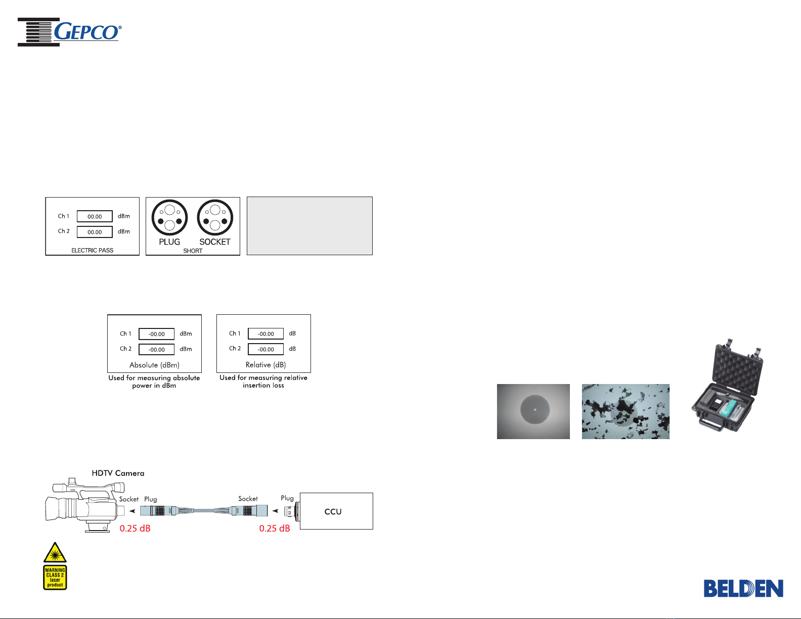
How To Measure Optical Signal Loss
•Each connection creates an additional 0.25dB of loss.
•Due to some higher optical RX sensitivities, it is possible to see as much as 5dB
of insertion loss in a system and still receive optical data from the camera head.
Short - Shaded Circle
Open - Flashing Circle
Miswire - Flashing Shaded Circle
•Optical pass/fail is determined by the end user. The screen indicates the fiber
loss per channel in Absolute (dBm) or Relative (dB) Mode. Press the up/down
arrow keys to toggle between these two modes.
How To Check the Tester
To make sure the tester is working properly, connect the Light Source Unit with the
Meter Unit and perform the following steps:
•Select Absolute Measurement Mode using up/down arrow keys.
• Press “OK” button to test the connection between the Meter and Light Source Units.
•Verify that optical power measured on Channel 1 and Channel 2 are greater than
-10dBm and less than -3dBm.
How To Zero Out The Tester
To zero out the tester, connect the Light Source Unit with the Meter Unit and
perform the following steps:
•Select Relative Measurement Mode using up/down arrow keys.
•Hold “OK” button for four seconds and release to zero out the meter.
•The bottom of the screen will indicate “Zero/Ref” when you release the “OK”
button.
Fiber Cleaning
Always make sure your connections are clean before connecting them to the Meter
Unit or Light Source Unit. With continuous use of the tester, periodic cleaning may
be necessary. Visit gepco.com/cleanfiber for fiber cleaning tips and instructional
video. Additional tools may be necessary for fiber inspection or cleaning.
Recommended Inspection Scope
Clean Fiber Contact Dirty (High Loss)
Fiber Contact
WARNING!
•Failure to properly clean fiber contacts before each connection could cause
severe damage to the contacts! Visit gepco.com/cleanfiber for fiber cleaning tips
or to view an instructional video.
•Do not attempt any repairs of the Meter and/or Light Source Units as this will
break the warranty seals and void the warranty. Repairs should only be performed
by an authorized Gepco repair facility.
Product meets eye safety requirement for Class 2 type lasers. LEMO is a trademark of Interlemo Holding, S.A.
Recommended inspection scope (Lemo®LEM-CL001) for identifying
optical loss-causing debris.
SMPTE Tester Manual 2016_0108.indd 2 1/15/2016 2:30:58 PM


