Bit Trade One USB Cable Checker2 User manual

USB CABLE CHECKER2
Instruction Manual 2 Nov 2020
Function introduction
This product has the following functions.
•USBChecking cable wire termination status
•Confirmation of built-in resistance value of type C plug( D for E Marker with or without)
•Checking the resistance value of the power line
•Ground fault check of plug shell
Description of each part
Precautions before use
At the time of purchase, the USBCableChecker2 is equipped with a battery for checking operation.
An insulating seal is sandwiched between the main unit and the main unit, so remove it before use.
Also, although the board is protected with acrylic, the connectors and other parts are exposed, so
please handle with care.
This product is a dedicated cable inspection device. Do not connect other USB devices. Risk of
breakage.
how to use
•• Judgment of plug conversion adapter
•After turning on the power of this product, connect the conversion adapter to either the A
side connector or the B side connector.
•If there is a built-in resistor connected to CC with a type C plug conversion connector, the
resistance value will be displayed on the OLED display.

•If the adapter has OTG function, "OTG ENABLE" will be displayed.
• • Cable judgment
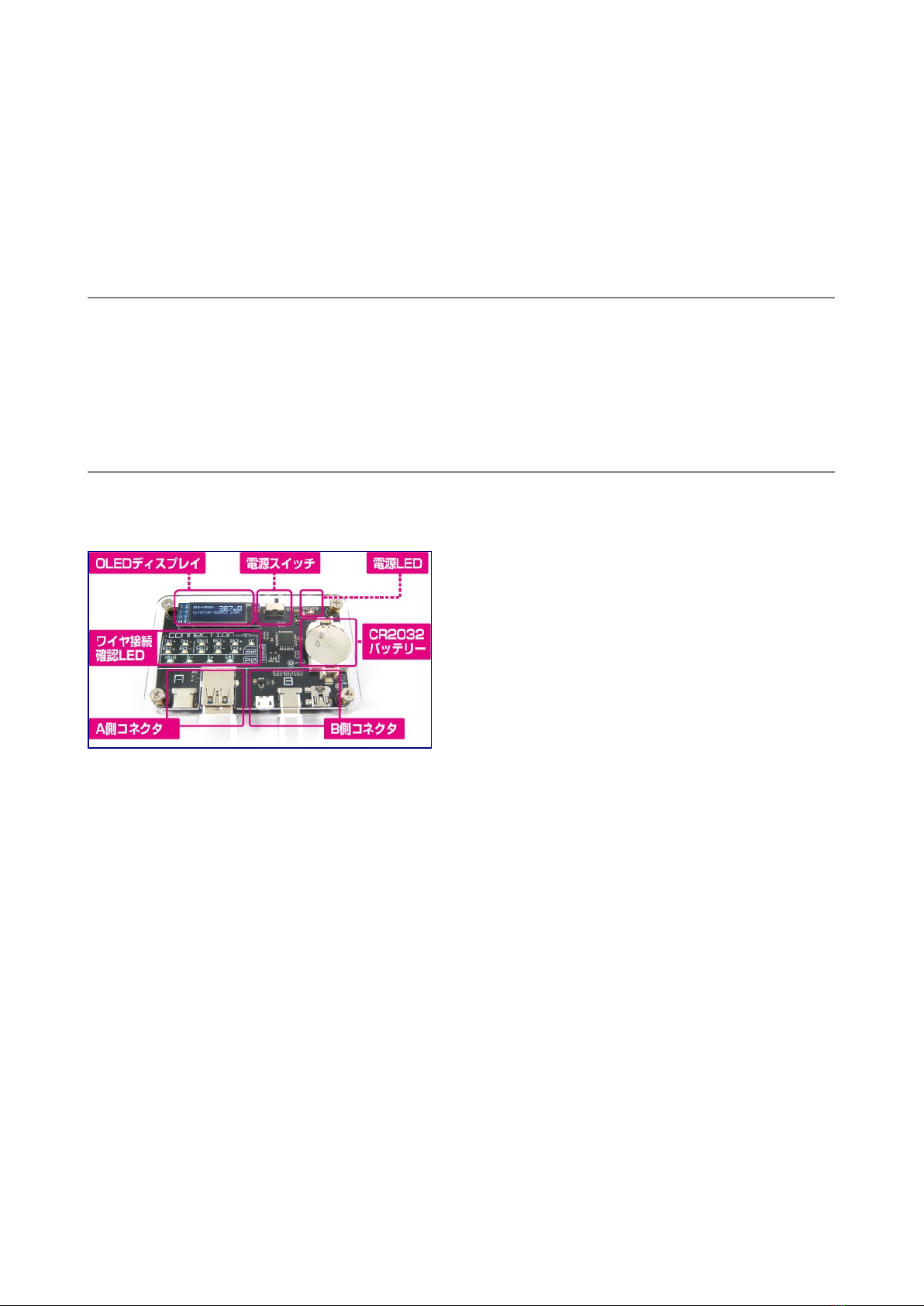
•After turning on the power of this product, connect the connector on the A side and the
connector on the B side with a USB cable.
•If the wire is connected, the LED corresponding to "CONNECTION" will light up.
• • OLED display display
•If both the VBUS and GND of the cable connected to the A side and B side are connected,
the total resistance value of the VBUS line and GND line resistance will be displayed on the
display.
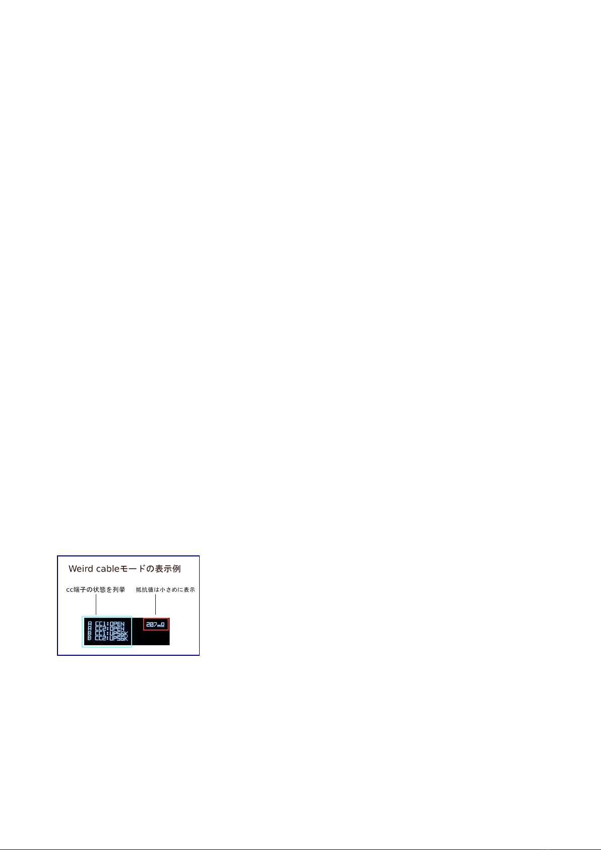
•When you connect a type C plug that has a built-in resistor inside the plug, the value of the
pull-up/pull-down resistor connected to CC and the corresponding maximum allowable
current value notified to the connected device are displayed.
•If a 10k pull-down resistor is detected, it will be judged as a MARKED cable.
O ED Explanation of display indication
[Resistance value]
This is the total resistance value of the GND line and VBUS line.
This includes USB plug-to-connector contact resistance. The unit is milliΩ and the accuracy is
±15%.
The measurement limit is 1100mΩ, above which "HIGH" is displayed.
[UP10K/SOURCE 3.0A]
It has a 10kΩ resistor connected between VBUS-CC in the C plug.
Make the USB device think the host is capable of supplying 3A current.
A cable with a resistor of this resistance value in the plug is out of the USB standard.
[UP22K/SOURCE 1.5A]
It has a 22kΩ resistor connected between VBUS and CC in the C plug.
Make the USB device think the host is capable of supplying 1.5A current.
A cable with a resistor of this resistance value in the plug is out of the USB standard.
[UP56K/SOURCE 0.5A]
It has a 56kΩ resistor connected between VBUS and CC in the C plug.
Make the USB device think the host is capable of supplying 0.5A current.
This value is the only connector built-in pull-up resistor allowed by the USB standard.

[DOWN1K/E-MARKED]
Have a 1kΩ resistor connected between GND and VCONN in the C plug.
This notifies the connected USB device that it is a cable with built-in E-marker IC.
[DOWN5.1K/SINK 0.5A]
It has a 5.1kΩ resistor connected between GND and CC in the C plug.
This allows the connected USB device to act as a host if possible.
[OTG ENAB E]
Although it is not a resistor, it lights up when the GND-ID terminals of the Mini-B and Micro-B
connectors are shorted.
This allows the connected USB device to act as a host if possible.
[SHE -GND SHORT(SIDE)]
Appears when the plug shell is connected to GND. The number in parentheses indicates whether the
connector on the conducting side is A or B.
A&B is displayed when both connectors are conductive.
In the type C-C cable, the standard stipulates that the GND and the shell are connected.
[SHIE D CONNECT]
"SHIELD CONNECT" is displayed when the shells at both ends are connected by wires
independent of GND.
Note that the shield wire of a legacy USB cable is normally connected to only one of the plugs, and
there is no continuity between the plugs.
Weird cable(weird cable) mode
If you find multiple CC pull-up or pull-down resistors in the cable, plug, the display will be
different than normal
Enter display mode. In this display mode, the resistance value is displayed small and the shell and
shield status are not displayed,
Lists the states of all CC pins on the A and B sides. This function is useful for discovering Type-C
cables that do not comply with the USB standard, such as being unable to distinguish between the
front and back.

Explanation of wire connection confirmation ED
[3.2]
Wire used for USB3.2 connection. The name of the differential line conforms to the terminal name
on the A side connector side.
CC
This wire is mainly used for host and device identification and USB D communication in TypeC
cables.
Whether or not various functions can be used is exchanged between devices through this wire.
SBUs
Side Band Use is a wire used when exchanging data (audio, video, etc.) other than USB data
communication.
Mainly used in alternate mode.
TX1/2 and RX1/2
A wire that communicates with USB 3.0 or later.
USB3.0 uses two pairs of wires for data communication (SuperSpeed /SS),
USB3.2 or later performs data communication (SuperSpeed+ / SS+) using 4 pairs of wires.
[2.0]
Wire used for USB1.0~USB2.0 connection.
D
This wire is used for data communication up to USB2.0 (Low Speed / Full Speed and High Speed).
VBUS and GND
This wire is used for power management.

Battery replacement method
When "LOW BATTERY" is displayed on the OLED display at startup, it is time to replace the
batteries.
As shown in the image above, slide the tip of the flathead screwdriver into the gap between the
negative terminal and the battery and use the principle of leverage to remove it.
Then install the new CR2032 battery with the positive side facing up.
Official page http://bit-trade-one.co.jp/adusbcim

USB CABLE CHECKER 2 FAQ
Q: Can USB CABLE CHECKER 2 be connected to an external device for measurement?
A: No.
USB CABLE CHECKER2 is a product for checking USB cables, not for connecting to other
devices.
Be sure to connect the USB cable to the A side and B side of the USB CABLE CHECKER2.
In the worst case, the device may be damaged by connecting other devices.
Q: Can it be used via a conversion connector?
A: It is not possible to use it with a conversion connector, but we have not verified it.
lease note that the performance of the connector also affects the results.
Q: Is it possible to identify the USB1 generation?
A: It is not possible to distinguish the first generation.
Table of contents