800-543-9038 USA 866-805-7089 CANADA 203-791-8396 LATIN AMERICA
23
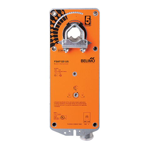
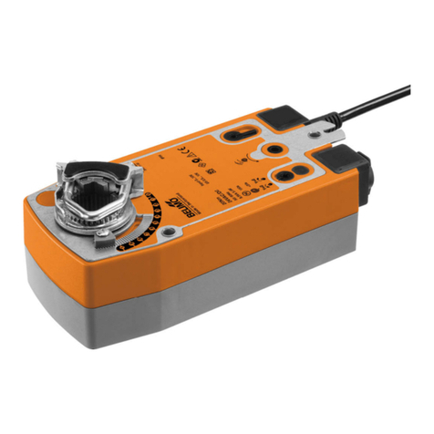
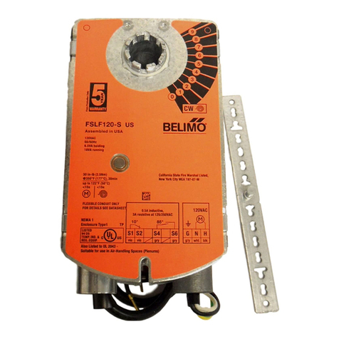
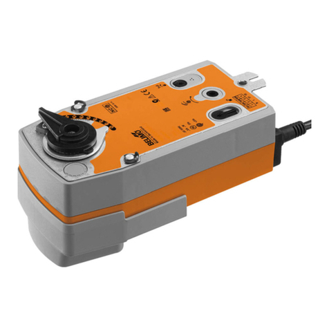
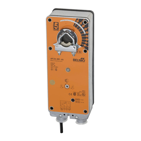
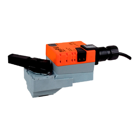
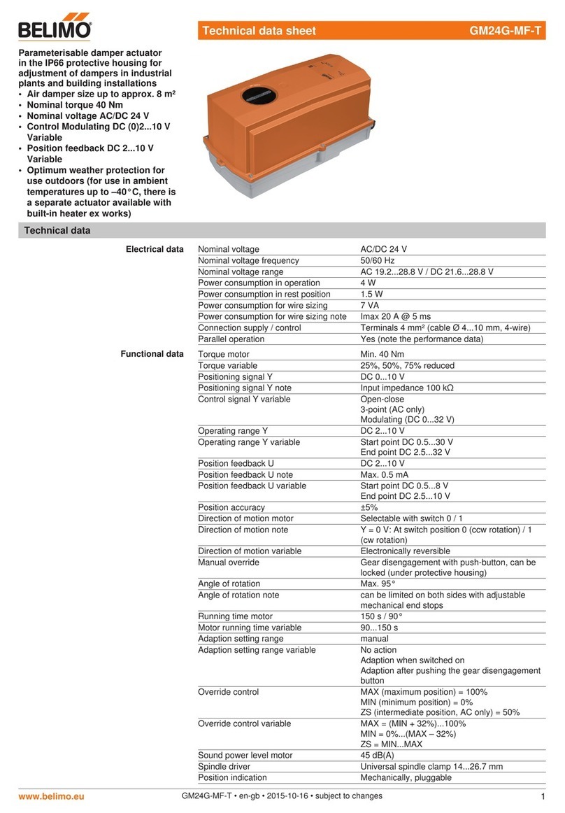
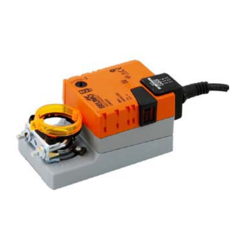
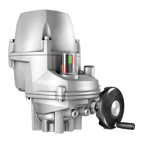
AF24-SR US
Proportional Damper Actuator, Spring Return Fail-Safe,
24 V for 2 to 10 VDC and 4 to 20 mA Control Signal.Output Signal of 2 to 10 VDC for Position Indication.
Accessories
AV 10-18 Shaft extension
IND-AF2 Damper position indicator
K4 US Universal clamp for 3/8” to 3/4” shafts
K4-1 US Universal clamp for up to 1.05” dia jackshafts
K4-H Universal clamp for hexshafts 3/8” to 5/8”
KH-AF Crankarm for up to 3/4” round shaft (Series 2)
KH-AF-1 Crankarm for up to 1.05” jackshaft (Series 2)
KH-AFV V-bolt kit for KH-AF and KH-AF-1
Tool-06 8mm and 10 mm wrench
SGA24 Min. and/or man. positioner in NEMA 4 housing
SGF24 Min. and/or man. positioner for flush panel mounting
ZG-R01 500 7resistor for 4 to 20 mA control signal
ZG-HTR Thermostat/Heater Kit
ZDB-AF2 US Angle of rotation limiter
ZG-100 Universal mounting bracket
ZG-101 Universal mounting bracket
ZG-102 Multiple actuator mounting bracket
ZG-103 Universal mounting bracket
ZG-104 Universal mounting bracket
ZG-106 Mounting bracket for Honeywell®Mod IV replacement or
new crankarm type installations
ZG-107 Mounting bracket for Honeywell®Mod III or Johnson®
Series 100 replacement or new crankarm type installations
ZG-108 Mounting bracket for Barber Colman®MA 3../4..,
Honeywell®Mod III or IV or Johnson®Series 100
replacement or new crankarm type installations
ZG-AF US Crankarm adaptor kit for AF/NF
ZG-AF108 Crankarm adaptor kit for AF/NF
ZS-100 Weather shield (metal)
ZS-150 Weather shield (polycarbonate)
ZS-260 Explosion-proof housing
ZS-300 NEMA 4X housing
NOTE: When using AF24-SR US actuators, only use accessories listed on this page.
For Actuator Wiring Information and Diagrams, Please See Belimo Wiring Guide (pg 349).
Typical Specification
Spring return control damper actuators shall be direct coupled type which
require no crankarm and linkage and be capable of direct mounting to a jackshaft
up to a 1.05” diameter. The actuator must provide proportional damper control in
response to a 2 to 10 VDC or, with the addition of a 500 7resistor, a 4 to 20 mA
control input from an electronic controller or positioner. The actuators must be
designed so that they may be used for either clockwise or counterclockwise fail-
safe operation. Actuators shall have control direction of rotation switch
accessible on its cover. Actuators shall use a brushless DC motor controlled by a
microprocessor and be protected from overload at all angles of rotation. Run
time shall be constant, and independent of torque. A 2 to 10 VDC feedback signal
shall be provided for position feedback or master-slave applications. Actuators
shall be UL Approved and CSA certified, have a 5 year warranty, and be
manufactured under ISO 9001 International Quality Control Standards. Actuators
shall be as manufactured by Belimo.
Wiring Diagrams
1Provide overload protection and disconnect as required.
2CAUTION Equipment damage!
Actuators may be connected in parallel.
Power consumption and input impedance must be observed.
3Actuators may also be powered by 24 VDC.
5Only connect common to neg. (–) leg of control circuits.
The ZG-R01 500 7resistor converts the 4 to 20 mA control signal to
2 to 10 VDC, up to 2 actuators may be connected in parallel.
WARNING Live Electrical Components!
During installation, testing, servicing and troubleshooting of this product, it maybe
necessary to work with live electrical components. Have a qualified licensed electrician
or other individual who has been properly trained in handling live electrical components
perform these tasks. Failure to follow all electrical safety precautions when exposed to live
electrical components could result in death or serious injury.
Control Signal
(+)
2 to 10 VDC
(–)
1 Common
2 + Hot
3 Y Input, 2 to 10V
5 U Output 2 to 10V
1
2
3
24 VAC Transformer
AF24-SR US
Line
Volts
W011
2 to 10 VDC control
W197_08
4 to 20 mA control
K20901 - 01/09 - Subject to change. © Belimo Aircontrols (USA), Inc.
