manuals.online logo
Brands
  1. Home
  2. •
  3. Brands
  4. •
  5. Belimo
  6. •
  7. Controllers
  8. •
  9. Belimo SY U24-SR Series Quick start guide

Belimo SY U24-SR Series Quick start guide

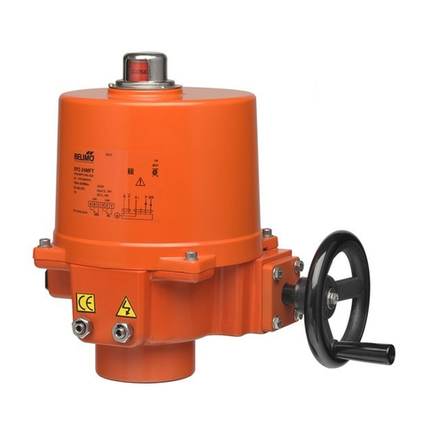
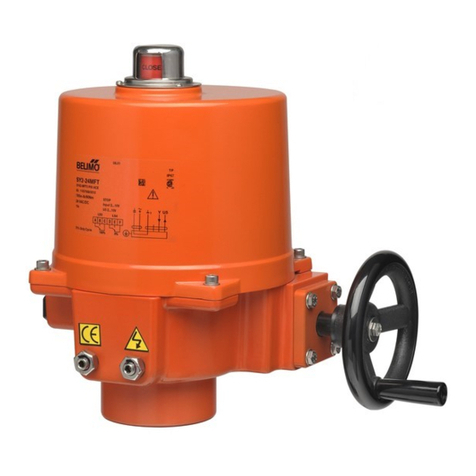
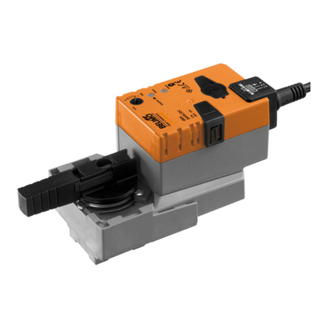
SY(2...9)U230-SR/MF-T actuator
SY(2...5)U24-SR/MF/MP-T modulating actuator
Circuit Board Set Up
Wiring diagram
Note: 1) Power supply Com/Neutral and control signal " - " wiring
to a common is prohibited.
Incorrect wiring will damage the actuator!
2) 75% duty cycle
Auxilary Switches
(SPDT Relays)
SY(2...5)U24-SR/MF/MP-T
SY(2...9)U230-SR/MF-T
Install to butterfly valve
Manual operate the actuator
to the similar open position
of the valve, which can be
judged by the valve disc or
the red line on the valve top
stem.
Fit coupling on the top stem
of the valve.
Mount the actuator onto the
coupling, manual operate
the actuator to align the holes
of valve top flange and actu-
ator bottom; then tighten the
bolts by wrench in diagonal
sequence.
Uncover the actuator, wire
according to the wiring diag-
ram, check the DIP switch
setting.
Power on to test run the
actuator, check its stroke
and feedback position, do
some adjustment if necessary.
Put the cover on and tighen
the bolts for it.
1).
2).
3).
4).
5).
6).
!
Auxiliary switch for closed
Auxiliary switch for open
(factory setting 3°)
(factory setting 87°)
The line indicates
the position of the
valve's disc
Before power on, make sure the input signal and voltage wiring are
in accordance with the actuator nameplate.
Subject to technical changes
F
ECBA
S1 100% S2 0%
D
TC2/TC4 (CW)
TC2/TC4 (CCW)
TC1/TC3 (CCW)
TC1/TC3 (CW)
Current position
Required position
1. How to adjust the travel cam
Perform an adaption after changing
the position of the travel cam.
1.1
Loosen the cam to be adjusted
with a 2.5 mm allen key;
1.2 By turning the key rotate and
adjust the cam as shown in
the right diagram;
1.3
Commission;
1.4
Tighten the cam after succes-
sful
adjustment.
LS4
LS3
LS2
LS1
TC4
TC3
TC2
TC1
shaft
Limiting of manual rotation with stop screws
SY quarter-turn actuator is provided with a limiting of manual rotation
device to avoid over-travel with the handwheel going beyond the 1/4-turn
rotation.
The actuator is supplied and tested for 90°electrical operation, and -2°
...92° limiting of manual rotation.
The limiting of manual rotation is realized by the stop screws 1and 2
( max. ± 2° which corresponding to 1 turn of the stop screw).
SY(2...5)U24-SR/MF/MP-T
SY(2...9)U230-SR/MF-T
Open
Adaption button
Close
If it's necessary to change the following settings, only
authorized and trained persons are allowed to do that.
!
Limit switches LS.. with travel cams TC..
The TC.. cams operating the LS.. limit switches rotate with the shaft.
Clockwise movement of the shaft closes the actuator, counterclockwise
opens the actuator.
There are 4 cams included , marked with two colors : blue for open,
silver for close; each cam can be set independently.
(factory setting 0°)
(factory setting 90°)
Closed switch
Open switch
!Connect via safety
isolating transformer
1
2
3
1- Stop screw for manual OPEN limit
2- Stop screw for manual CLOSED limit
3- Handwheel connection
(Note: SY1 without the device)
The stop screws must be sec-
ured with the lock nut after any
adjustment. (by both a allen key
and a wrench)
The 90° travel must always be
limited by the travel limit sw-
it
ches so they must be set to
trip just BEFORE stop screw's
contact. To achieve this, loose
stop screws by 2 1/2 turns. Then,
after travel limit switch setting is
terminated, (see paragraph
Limit switches LS.. with travel cams TC..), operate the actuator elect-
rically to
closed position. Now rotate the stop screw 2to closed position,
re-loose 1 turn, and secure by lock nut. Proceed in the same way for stop
screw 1in open position.
It is emphasized that the limiting of manual rotation device is only a design
feature to prevent over-travel when the actuator is being operated manually,
not a safety function to prevent over-travel in the event of travel limit
switch failure.
2. Closed position (0%) setting
2.1
2.2 Power on.
The actuator will stop
.
2.3
Adjust travel cam TC2 in the closed position.
Check whether
LS2 switch trips prior to manual operation stop.
(The fanshaped cam which connected with the potentiometer need
to be loosed firstly, then retightened after the
travel limit switches
setting is
terminated.)
(
So when motor stops at fully closed position, it should be
possible to further operate the handwheel CW 1/2...3/4 turn.
Otherwise the stop screw for close need to be adjusted.)
Proceed in the similar way for TC1 in open position.
± 1°
T T
AC 24 V AC 230 V
-
Y1U5 C1C22
+-
+
~
T
~
T
N L
Direction switch
Direction switch
Y2 standard
Y2 standard
SY(2...5)U24-SR/MF/MP-T
SY(2...9)U230-SR/MF-T
71102-00001.A
SY(2...9)U230-SR/MF-T 执行器
SY(2...5)U24-SR/MF/MP-T 调节型执行器
调节板设置
接线说明
1) 禁止将电源零线与控制信号零线共线。
错误的接线可能会损坏执行器。
2) 75% 工作频率
SY(2...5)U24-SR/MF/MP-T
SY(2...9)U230-SR/MF-T
与蝶阀安装
根据阀板或阀轴顶端红线所指示
位置,将执行器手动打开至该
位置。
将连接件套在阀轴顶端。
将执行器套上连接件,之后手
动操作执行器使阀门上法兰螺
栓孔与执行器下方安装孔对齐,
然后通过扳手将螺栓按对角线
顺序紧固。
拆下执行器上盖,按接线说明
接线。
给执行器通电并试运行,检查
运行状况与反馈位置,需要时
调整。
装好上盖并紧固螺栓。
1).
2).
3).
4).
5).
6).
!
通电前请检查各项接线是否与执行器标牌中接线说明一致。
Subject to technical changes
F
ECBA
S1 100% S2 0%
D
TC2/TC4 (CW)
TC2/TC4 (CCW)
TC1/TC3 (CCW)
TC1/TC3 (CW)
1. 如何调整行程凸轮
调整过凸轮位置后需执行一次
“daption” 自适应 。
1.1
将
2.5 mm
内六角扳手插入所要设定
的凸轮的螺孔内,松动螺栓。
1.2
用内六角扳手挑动凸轮,按左图
所示方法调整凸轮位置,并预拧
紧螺丝。
1.3
通电检查限位开关
LS
的动作是否
使阀板到位。
1.4
成功调整完毕后,务必锁定凸轮。
LS4
LS3
LS2
LS1
TC4
TC3
TC2
TC1
轴
SY(2...5)U24-SR/MF/MP-T
SY(2...9)U230-SR/MF-T
Adaption-自适应按钮
只有经过培训和授权的人员才允许改变以下设置
!
限位开关 LS.. 与行程凸轮 TC..
!
1
2
3
2. 关闭位置 (0%) 设定
2.1
2.2
接通电源,直至执行器停止在全关位置。
2.3
调节行程凸轮TC2至全关位置。
检查电子限位行程是否在机械限位范围之内。
(在调节前将与电位计相连的凸轮先松开,待调整过程成功
完成后再紧固。)
(即马达于全关位置停止后,逆时针方向操作手轮能旋转
1/2...3/4圈,
否则需调整止附螺栓。)
调整全开位置方法与上述类似。
± 1°
T T
AC 24 V AC 230 V
-
Y1U5 C1C22
+-
+
~
T
~
T
N L
转向开关
Y2为出厂设置
SY(2...5)U24-SR/MF/MP-T
SY(2...9)U230-SR/MF-T
通过安全隔离
的变压器连接 辅助开关
注:
转向开关
Y2为出厂设置
该线指示阀
板当前位置
行程凸轮TC.. 随轴的转动使电子行程开关LS.. 动作。
轴顺时针方向转动时执行器关闭,逆时针转动时执行器打开。
共有4个行程凸轮,以两种颜色标记:蓝色表示控制打开状态,
银行表示控制关闭状态;任何一个行程凸轮都可以单独调整。
辅助开关用于全关位置反馈
辅助开关用于全开位置反馈
(出厂设置 3°)
(出厂设置 87°)
用于全关限位开关定位(出厂设置 0°)
用于全开限位开关定位(出厂设置 90°)
当前位置
正确位置
开
关
机械限位
SY执行器具有机械限位。
执行器经过测试只提供90°电子行程以及-2°...92°的机械限位范围。
机械限位由止附螺栓1和止附螺栓2控制
( 转动限位螺栓1圈相当于最多2°)。
止附螺栓被调整后必须紧固螺母
(通过一个内六角与一个扳手)
电子行程必须被设定在90°以内
并在机械限位范围之内。
当电子行程设定结束后,
(参见:电子行程开关LS.. 与行程
凸轮TC.. 部分)可将止附螺栓
拧松2圈半左右,然后通电运
转执行器到全关位置。
将止附螺栓2顺时针旋至尽头后,再逆时针转1圈,紧固螺母。
对于止附螺栓1请重复上述操作。
需要强调的是SY执行器机械限位仅为了避免手轮过度转动,而不可替代
电子行程开关的作用。
1- “全开”止附螺栓
2- “全关”止附螺栓
3- 连接手轮,用于手动操作

This manual suits for next models

7

Other Belimo Controllers manuals

Belimo NM24A-MOD Instruction Manual

Belimo

Belimo NM24A-MOD Instruction Manual

Belimo LF24-3 US User manual

Belimo

Belimo LF24-3 US User manual

Belimo AR 24-3 Series User manual

Belimo

Belimo AR 24-3 Series User manual

Belimo AMQB24-MFT User manual

Belimo

Belimo AMQB24-MFT User manual

Belimo NIMVR C Series User manual

Belimo

Belimo NIMVR C Series User manual

Belimo FSNF User manual

Belimo

Belimo FSNF User manual

Belimo PRCA-S2-T Instruction Manual

Belimo

Belimo PRCA-S2-T Instruction Manual

Belimo HR series User manual

Belimo

Belimo HR series User manual

Belimo SY4 Series User manual

Belimo

Belimo SY4 Series User manual

Belimo LF24-SR US User manual

Belimo

Belimo LF24-SR US User manual

Belimo NKQB24-1 User manual

Belimo

Belimo NKQB24-1 User manual

Belimo EFB Series User manual

Belimo

Belimo EFB Series User manual

Belimo NF24A User manual

Belimo

Belimo NF24A User manual

Belimo CQB24-3 User manual

Belimo

Belimo CQB24-3 User manual

Belimo LMC24 User manual

Belimo

Belimo LMC24 User manual

Belimo GM24A-MOD Instruction Manual

Belimo

Belimo GM24A-MOD Instruction Manual

Belimo FGVL Series User manual

Belimo

Belimo FGVL Series User manual

Belimo AVK230A-3 User manual

Belimo

Belimo AVK230A-3 User manual

Belimo LRB24-MFT User manual

Belimo

Belimo LRB24-MFT User manual

Belimo AVK230A-3 Instruction Manual

Belimo

Belimo AVK230A-3 Instruction Manual

Belimo SY 3-T Series User manual

Belimo

Belimo SY 3-T Series User manual

Belimo AFX24LON User manual

Belimo

Belimo AFX24LON User manual

Belimo LF24 US User manual

Belimo

Belimo LF24 US User manual

Belimo NM24A-MP Instruction Manual

Belimo

Belimo NM24A-MP Instruction Manual

Popular Controllers manuals by other brands

WindowMaster WMS 309-n Installation instructions manual

WindowMaster

WindowMaster WMS 309-n Installation instructions manual

HANYOUNG NUX TPR-3N instruction manual

HANYOUNG NUX

HANYOUNG NUX TPR-3N instruction manual

Oriental motor DRS Series operating manual

Oriental motor

Oriental motor DRS Series operating manual

RockJam RJMK25 user guide

RockJam

RockJam RJMK25 user guide

Tolomatic ACS Hardware installation guide

Tolomatic

Tolomatic ACS Hardware installation guide

superbrightleds RGB-MDC83 user manual

superbrightleds

superbrightleds RGB-MDC83 user manual

Data Video RMC-180 MARK II instruction manual

Data Video

Data Video RMC-180 MARK II instruction manual

OzCharge OC-RM800i owner's manual

OzCharge

OzCharge OC-RM800i owner's manual

Hobby-Wing Xerun XR10 Pro user manual

Hobby-Wing

Hobby-Wing Xerun XR10 Pro user manual

wattstopper MRDS10 installation instructions

wattstopper

wattstopper MRDS10 installation instructions

Fairplay MP-70/50 Series user guide

Fairplay

Fairplay MP-70/50 Series user guide

Oriental motor AZX Series operating manual

Oriental motor

Oriental motor AZX Series operating manual

wattstopper legrand LMRC-102 quick start guide

wattstopper

wattstopper legrand LMRC-102 quick start guide

IMG STAGE LINE DMX-510USB instruction manual

IMG STAGE LINE

IMG STAGE LINE DMX-510USB instruction manual

Alfalaval LKLA NC instruction manual

Alfalaval

Alfalaval LKLA NC instruction manual

Alfalaval ThinkTop v.3.0 instruction manual

Alfalaval

Alfalaval ThinkTop v.3.0 instruction manual

Bluesky SB3000i Installation and operation

Bluesky

Bluesky SB3000i Installation and operation

Aqua Medic T controller twin Operation manual

Aqua Medic

Aqua Medic T controller twin Operation manual

manuals.online logo
manuals.online logoBrands
  • About & Mission
  • Contact us
  • Privacy Policy
  • Terms and Conditions

Copyright 2025 Manuals.Online. All Rights Reserved.