manuals.online logo
Brands
  1. Home
  2. •
  3. Brands
  4. •
  5. Belimo
  6. •
  7. Controllers
  8. •
  9. Belimo SY-3-T-TS Series Quick start guide

Belimo SY-3-T-TS Series Quick start guide

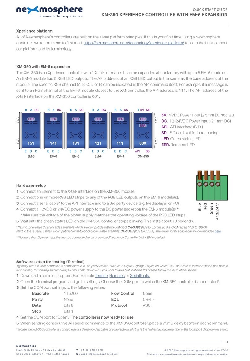
Wiring Diagram
"L" (Live wire) connects to terminal #3 for OPEN.
"L" connects to terminal #4 for CLOSE.
Connect "L" to terminal #7 to activate the internal heater. (No
need to connect internal heating for indoor applications with
constant temperature conditions.)
Note:
1)
"L"
shall
not
connect
to terminal #3 and #4
simultaneously
2) Relays are needed in parallel connection of
several actuators!
3) 30% duty cycle
If it is necessary to change the following settings,
only authorized and trained personnel are allowed
to do so.
Install to butterfly valve
1)
Manual operate the actuator to the
similar open position of the valve,
which can be judged by the valve
disc.
2) Fit coupling on the top stem of the
valve.
3) Mount the actuator onto the
coupling, manual operate the
actuator to align the holes of valve
top flange and actuator bottom;
then tighten the bolts by wrench in
diagonal sequence.
4) Remove the actuator cover, wire
according to the wiring diagram.
5) Power on to test run the actuator,
check its travel angle and feedback
position, make adjustment if
necessary.
6) Put the cover on and tighten the
bolts
Limit switches LS.. with travel cams TC..
Note:
TC1 and TC2 switches are carefully calibrated at factory and
adjustment is normally not needed. Adjustment on these limit
switches must be carried out by trained personnel and wrong
adjustment could damage the system.
The TC.. cams rotate with the shaft, and trigger the LS.. limit
switches. Clockwise movement of the shaft closes the actuator,
counterclockwise movement opens the actuator.
There are 4 cams included, marked with two colors: blue for open,
silver for close; each cam can be set independently.
1. How to adjust the travel
cam
1.1. Loosen the cam to be
adjusted with a
2.5mm allen key;
1.2. By turning the key,
rotate and adjust the
cam as shown in the
diagram on the right;
1.3.
Check if the valve can open and close properly
1.4. Tighten the cam after successful adjustment
2. Closed position (0%) setting
2.1. Connect power to terminal #1 and #4.
2.2. Power on. The actuator will drive CW to fully closed
position.
2.3. Adjust travel cam TC2 in the closed position.
2.4. Check whether LS2 switch trips prior to manual
operation stop. (When motor stops at fully closed
position, it should be possible to further operate the
handwheel CW ½…¾ turn. Otherwise the stop screw for
manual closed limit need to be adjusted.)
3. Adjust similarly for TC1 in open position by connecting power
to terminal #1 and #3.
Limiting of manual rotation with top screws
Note: Top screws for manual OPEN and CLOSE limit are carefully
calibrated at factory and adjustment is normally not needed.
Adjustment on these screws must be carried out by trained
personnel and wrong adjustment could damage the system.
SY quarter-turn actuator is provided with a limiting of manual
rotation device to avoid over-travel with the handwheel going
beyond the ¼-turn rotation.
The actuator is supplied and tested for 90⁰ electrical operation, and
-2⁰…92⁰ limiting of manual rotation.
The limiting of manual rotation is realized by the stop screws 1 and
2 (max. ±2⁰ which corresponding to 1 turn of the stop screw).
The top screws must be secured
with the lock nut after any
adjustment. (by both an allen key
and a wrench)
The 90⁰ travel must always be
limited by the travel limit
switches so they must be set to
trip just BEFORE contacting the
Stop screws.
To achieve this, loose stop screws by 2½ turns. After travel limit
switch setting is completed, operate the actuator electrically to
closed position. (See paragraph Limit switches LS.. with travel
cams TC..) Now rotate the stop screw 2 to closed position, re-
loosen 1 turn, and secure by lock nut. Proceed in the same way for
stop screw 1 in open position. The limiting of manual rotation
device is only a design feature to prevent over-travel when the
actuator is being operated manually, it is not a safety function to
prevent over-travel in the event of travel limit switch failure.
Overload protection
This actuator is equipped with a torque switch that breaks the
power when an overload condition appears. An alarm switch will
be triggered when the torque limit switch activates.
TS3: When the torque value is overloaded, terminal #8 will loop to
terminal #9 when actuator turns counterclockwise.
TS4: When the torque value is overloaded, terminal #11 will loop to
terminal #12 when actuator turns clockwise.
Auxiliary switch for closed (factory setting 3⁰)
Auxiliary switch for open (factory setting 87⁰)
Closed switch (factory setting 0⁰)
Open switch (factory setting 90⁰)
!
7
2105-00001.B
!
SY..-3-T-TS actuators for 3-point control or open/close control
1- Stop screw for manual OPEN limit
2- Stop screw for manual CLOSED limit
3- Handwheel connection
接线说明
L(火线)与端子#3 连接为打开
L 与端子#4 连接为关闭
L 与端子#7 连接,激活内置电加热(恒温的室内应用中,无需连
接内置电加热。)
注: 1) 禁止将"L"与#3 和 #4 端子同时连接。
2) 当多个执行器并联连接时需于接线点加继电器!
3) 30% 工作频率
只有经过培训和授权的人员才允许改变以下设置
与蝶阀安装
1) 根据阀板所指示位置,将执行器
手动打开至该位置。
2) 将连接件套在阀轴顶端。
3) 将执行器套上连接件,之后手动
操作执行器使阀门上法兰螺栓孔
与执行器下方安装孔对齐,然后
通过扳手将螺栓按对角线顺序紧
固。
4) 拆下执行器上盖,按接线说明接
线。
5) 给执行器通电并试运行,检查运
行状况与反馈位置,需要时调
整。
6) 装好上盖并紧固螺栓。
电子行程开关 LS.. 与行程凸轮 TC..
注意:TC1 和 TC2 开关在出厂前经过仔细校准,通常不需要调整。
必须由经过培训的人员对这些限位开关进行调整,调整不当可能会
损坏系统。
行程凸轮 TC.. 随轴的转动并使电子行程开关 LS.. 动作。 轴顺时针
方向转动时执行器关闭,逆时针转动时执行器打开。 共有 4 个行程
凸轮,以两种颜色标记:蓝色表示控制打开,银色表示控制关闭;
任何一个凸轮都可以单独调整。
1. 如何调整行程凸轮
1.1. 将 2.5 mm 内六角扳手
插入所要设定的行程凸
轮 的 螺 孔 内 , 松 动 螺
栓。
1.2. 用内六角扳手按图所示方法调 整行程凸轮位置,并预拧
紧螺丝。
1.3. 检查阀门是否能正常开或关。
1.4. 成功调整完毕后必须锁定行程凸轮。
2. 关闭位置(0%)设定
2.1. 端子 #1, #4 连接电源;
2.2. 通电,执行器会顺时针转动至全关位置。
2.3. 调节行程凸轮 TC2 至全关位置。
2.4. 检查电子限位行程是否在机械限位范围之内。(即马达
于 全 关 位 置 停 止 后 , 逆 时 针 方 向 操 作 手 轮 能 旋 转
1/2...3/4 圈, 否则需调整止附螺栓。)
3. 端子#1 和#3 连接电源,通电后,对 TC1 开启位置(100%)通
过上述步骤进行设定。
机械限位
注意:手动开/关的止附螺栓在出厂前经过仔细校准,通常不需要调
整。 必须由经过培训的人员对止附螺栓进行调整,调整不当可能
会损坏系统。
SY 执行器具有机械限位。
执行器经过测试只提供 90°电子限位行程以及-2°...92°的机械限位
范围。 机械限位由止附螺栓 1 和止附螺栓 2 控制(转动止附螺栓 1
圈相当于最多 2°)。
止附螺栓被调整后必须紧固螺母
(通过一个内六角与一个扳手) 电
子行程必须被设定在 90°以内 并
在机械限位范围之内。
当电子行程设定结束后, (参见:
电子行程开关 LS.. 与行程 凸轮
TC.. 部分)可将止附螺栓 拧松 2 圈
半左右,然后通电运转执行器到
全关位置。
将止附螺栓 2 顺时针旋至尽头后,再逆时针转 1 圈,紧固螺母。
对于止附螺栓 1 请重复上述操作。 需要强调的是 SY 执行器机械限
位仅为了避免手轮过度转动,而不可替代电子行程开关的作用。
过扭矩保护
该执行器配有一个扭矩开关,当出现过载情况时,该开关切断电
源。 当扭矩限制开关启动时,警报开关将被触发。
TS3: 当扭矩值过载时,端子#8 与端子#9 导通(出厂默认为逆时针
方向,阀门打开)。
TS4: 当扭矩值过载时,端子#11 与端子#12 导通(出厂默认为顺时
针方向,阀门关闭)。
辅助开关用于全开位置反馈(出厂设置 87°)
!
!
SY..-3-T-TS 执行器用于三态控制或开/关控制
1- "全开"止附螺栓
2- "全关"止附螺栓
3- 连接手轮,用于手动操作
辅助开关用于全关位置反馈(出厂设置 3°)
轴
用于全关限位开关定位(出厂设置 0°)
用于全开限位开关定位(出厂设置 90°)
开
关
当前位置
正确位置

This manual suits for next models

3

Other Belimo Controllers manuals

Belimo ZEV Instruction manual
Belimo

Belimo ZEV Instruction manual
Belimo PRCA-S2-T Instruction Manual

Belimo

Belimo PRCA-S2-T Instruction Manual
Belimo AVK230A-3 Instruction Manual
Belimo

Belimo AVK230A-3 Instruction Manual

Belimo AF24-LIN US User manual

Belimo

Belimo AF24-LIN US User manual

Belimo VAV-Compact D3 User manual

Belimo

Belimo VAV-Compact D3 User manual

Belimo FSNF230 US User manual

Belimo

Belimo FSNF230 US User manual

Belimo AMB24-SR-X1 User manual

Belimo

Belimo AMB24-SR-X1 User manual

Belimo SY4 Series User manual

Belimo

Belimo SY4 Series User manual

Belimo LMQB24-MFT Instruction manual

Belimo

Belimo LMQB24-MFT Instruction manual

Belimo ZSN-BF User manual

Belimo

Belimo ZSN-BF User manual

Belimo TFC120-S US User manual

Belimo

Belimo TFC120-S US User manual

Belimo FS Series Use and care manual

Belimo

Belimo FS Series Use and care manual

Belimo SRF24A-SR Instruction Manual

Belimo

Belimo SRF24A-SR Instruction Manual

Belimo LMB series Guide

Belimo

Belimo LMB series Guide

Belimo TRANE TTF Series Guide

Belimo

Belimo TRANE TTF Series Guide

Belimo LF-2 Series User manual

Belimo

Belimo LF-2 Series User manual

Belimo NMB24-SR User manual

Belimo

Belimo NMB24-SR User manual

Belimo ZTH Series Quick start guide

Belimo

Belimo ZTH Series Quick start guide

Belimo GMX24-3-X1 User manual

Belimo

Belimo GMX24-3-X1 User manual

Belimo LMQB24-1 User manual

Belimo

Belimo LMQB24-1 User manual

Belimo AFX24LON User manual

Belimo

Belimo AFX24LON User manual

Belimo NF24A-SR-S2 Instruction Manual

Belimo

Belimo NF24A-SR-S2 Instruction Manual

Belimo PRCA-S2-T Instruction Manual

Belimo

Belimo PRCA-S2-T Instruction Manual

Belimo SMQ24G-SR Instruction Manual

Belimo

Belimo SMQ24G-SR Instruction Manual

Popular Controllers manuals by other brands

Bender CC612 manual

Bender

Bender CC612 manual

D-Link DWC-1000 user manual

D-Link

D-Link DWC-1000 user manual

Banda Solar LG30A user manual

Banda Solar

Banda Solar LG30A user manual

Omron CJ1W-CT021 Operation manual

Omron

Omron CJ1W-CT021 Operation manual

pitsco Tetrix Max User & Technical Guide

pitsco

pitsco Tetrix Max User & Technical Guide

Panasonic CZ-CAPEK2 Installation and service instructions

Panasonic

Panasonic CZ-CAPEK2 Installation and service instructions

Siemens Simatic S7-300 Hardware and installation manual

Siemens

Siemens Simatic S7-300 Hardware and installation manual

ARIS Linearis N+ Original declaration of incorporation with manual

ARIS

ARIS Linearis N+ Original declaration of incorporation with manual

Solter AUTONOMY 3500 manual

Solter

Solter AUTONOMY 3500 manual

Kostal inveor operating manual

Kostal

Kostal inveor operating manual

SOMFY animeo IB + 1822064 installation guide

SOMFY

SOMFY animeo IB + 1822064 installation guide

Sinclair XK64 user manual

Sinclair

Sinclair XK64 user manual

Element Labs Versa Drive C1 user manual

Element Labs

Element Labs Versa Drive C1 user manual

National Instruments PXI-8109 user manual

National Instruments

National Instruments PXI-8109 user manual

Nordson Gun Controller manual

Nordson

Nordson Gun Controller manual

SKF CAHB-20E Installation, operation and maintenance manual

SKF

SKF CAHB-20E Installation, operation and maintenance manual

Borg Warner Delco Remy 28MT Diagnostic Procedures Manual

Borg Warner

Borg Warner Delco Remy 28MT Diagnostic Procedures Manual

Johnson Controls FEC26 Series installation guide

Johnson Controls

Johnson Controls FEC26 Series installation guide

manuals.online logo
manuals.online logoBrands
  • About & Mission
  • Contact us
  • Privacy Policy
  • Terms and Conditions

Copyright 2025 Manuals.Online. All Rights Reserved.