manuals.online logo
Brands
  1. Home
  2. •
  3. Brands
  4. •
  5. MFJ
  6. •
  7. Controllers
  8. •
  9. MFJ MFJ-1278 User manual

MFJ MFJ-1278 User manual

This manual suits for next models

1

Other MFJ Controllers manuals

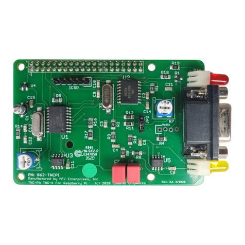
MFJ MFJ-1270Pi User manual

MFJ

MFJ MFJ-1270Pi User manual

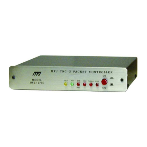
MFJ MFJ-1270C User guide

MFJ

MFJ MFJ-1270C User guide

MFJ MFJ-1270X User manual

MFJ

MFJ MFJ-1270X User manual

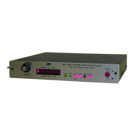
MFJ Multi-mode Data Controller MFJ-1278B User manual

MFJ

MFJ Multi-mode Data Controller MFJ-1278B User manual

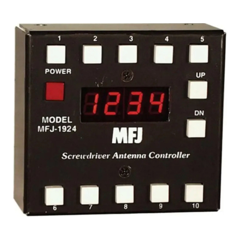
MFJ MFJ-1924 User manual

MFJ

MFJ MFJ-1924 User manual

MFJ MFJ-1270X User manual

MFJ

MFJ MFJ-1270X User manual

MFJ Memory Keyer MFJ-493 User manual

MFJ

MFJ Memory Keyer MFJ-493 User manual

MFJ MFJ-1270X User manual

MFJ

MFJ MFJ-1270X User manual

Popular Controllers manuals by other brands

Sunricher SR-ZV9003T3-RGBW-US Installation

Sunricher

Sunricher SR-ZV9003T3-RGBW-US Installation

Ksenia intro Installation and configuration manual

Ksenia

Ksenia intro Installation and configuration manual

Inovance CAN200 Series manual

Inovance

Inovance CAN200 Series manual

Gauzy LC6 FLEX Controller Installation and operation guide

Gauzy

Gauzy LC6 FLEX Controller Installation and operation guide

Viking SLP-1 Technical practice

Viking

Viking SLP-1 Technical practice

CKD KBX-30E-U Series instruction manual

CKD

CKD KBX-30E-U Series instruction manual

Sharp Energy Sun Flux User manual & installation guide

Sharp Energy

Sharp Energy Sun Flux User manual & installation guide

Yamaha RCX40 user manual

Yamaha

Yamaha RCX40 user manual

AB Quality PowerFlex 400 Frames D-H Service bulletin

AB Quality

AB Quality PowerFlex 400 Frames D-H Service bulletin

Yamaha MJC8 owner's manual

Yamaha

Yamaha MJC8 owner's manual

AL-KO ATC operating instructions

AL-KO

AL-KO ATC operating instructions

Savant SmartControl 2 Deployment guide

Savant

Savant SmartControl 2 Deployment guide

GameSir T3S user manual

GameSir

GameSir T3S user manual

Kostal inveor operating manual

Kostal

Kostal inveor operating manual

Emerson Yarway 20-55 Operating and safety instructions

Emerson

Emerson Yarway 20-55 Operating and safety instructions

CoCo ACM-LV24 Quick installation guide

CoCo

CoCo ACM-LV24 Quick installation guide

Brooks SLA5810/20 Installation and operation manual

Brooks

Brooks SLA5810/20 Installation and operation manual

SIGMA TEK SR 011 Technical manual

SIGMA TEK

SIGMA TEK SR 011 Technical manual

manuals.online logo
manuals.online logoBrands
  • About & Mission
  • Contact us
  • Privacy Policy
  • Terms and Conditions

Copyright 2025 Manuals.Online. All Rights Reserved.

Easy-to follow guide to connecting your new
MFJ-1278/1278T Multi-Mode Data Controller
between your radio and computer
CAUTION: Read all Instructions Before Operating Equipment
MFJ ENTERPRISES, INC.
P.O.BOX 494, MISSISSIPPI STATE, MS 39762, USA
COPYRIGHT © 1990 MFJ ENTERPRISES, INC.
MFJ-1278 & MFJ-1278T Fast-Start Manual
1
Introduction
This MFJ-1278 Fast-Start Manual is intended to provide you with the minimum Information ne es-
sary to install your MFJ-1278 or MFJ-1278T "Turbo" Multi-Mode as qui kly as possible. For detail
operation, please see the main instru tion manual.
The differen e between the MFJ-1278 and the MFJ-1278T is that the MFJ-1278T has the 2400 mo-
dem installed. If your MFJ-1278 does not have the 2400 modem installed, it an be pur hased sep-
arately (Model MFJ-2400) and installed by the user. With the 2400 modem installed, your MFJ-
1278 an operate 300 baud, 1200 baud and 2400 bps pa kets.
The Computer Installation se tion assumes that you have pur hased one of the MFJ Starter Pa ks.
If you are not using the MFJ Starter Pa k, you should refer to the main MFJ-1278 Owner's Manual
for Computer interfa e onne tions. However, you may still use the Radio Installation and the oth-
er parts of the Fast-Start manual.
Your MFJ Starter Pa k onsists of terminal Software and a serial able to onne t between the
MFJ-1278 and your Computer.
The Starter Pa ks available are MFJ-1289 for IBM and ompatible Computers, MFJ-1282B for Com-
modore 64/128 Computers and MFJ-1287B for the Ma intosh Computer.
MFJ-1289 Starter Pa k in ludes the MULTICOM advan ed terminal program. MULTICOM supports
multi-gray levels FAX and SSTV re eiving and transmitting. It also supports VGA pa ket pi ture
passing. Other unique features this program gives you are: Auto-Router™ lets you store digipeater
node routes for easy exe ution, Multi-Word™ makes it easy for you to transmit any portion of a
file, Pa ket Multi-Plex™ lets you send and re eive pa ket messages during binary file transfer.
MULTICOM is fully menu driver, and it is very easy to use. It has dedi ated fun tion buffers for
ea h mode of Operation.
MFJ-1289 MULTICOM is highly re ommended if you are using an IBM or ompatible Computer with
your MFJ-1278.
MFJ-1282B for the Commodore C64/128 and MFJ-1287B for the Ma intosh Computers also support
Multi-Gray FAX/SSTV Operation.
MFJ-1278 & MFJ-1278T Fast-Start Manual
2
I. INSTALLATION
A. Pow r Supply
Your MFJ-1278 is supplied with an AC adapter. Plug the power supply into a 110 VAC outlet and
plug the 2.1 mm oaxial plug into "POWER" ja k lo ate at the rear of the MFJ-1278.
For operation on AC line voltage other than 110 V AC, you must obtain a suitable AC adapter
whi h will provide 12 VDC at 500 mA to operate your MFJ-1278.
If it is ne essary for you to wire the 2.1 mm oaxial plug for your power supply, wire the 2.1 mm
plug so that the enter pin is positive and the outside sleeve is ground.
B. Comput r Int rfac s
This omputer installation applies to those who are using the MFJ Starter Pa k with IBM and om-
patibles, Commodore C64/128 and Ma intosh omputers. If you are not using one of these om-
puters, or if you are not using an MFJ Starter Pa k, then you must refer to the main MFJ-1278 in-
stru tion manual for omputer installation.
The able supplied with the Starter Pa k must be t used in this installation. If you are not using
the Starter Pa k omputer able to make this onne tion, you should refer to the main MFJ-1278
instru tion manual, Chapter 2 "Computer Interfa ing" to verify that the able you are using is or-
re tly wired.
WARNING: IMPROPERLY WIRED CABLE COULD DAMAGE YOUR MFJ-1278 AND/OR YOUR COM-
PUTER!
1. Conne t the able from the omputer to the MFJ-1278 as follows:
IBM and ompatibles:
Conne t the able end with DB-25 male to the ba k of the MFJ-1278 RS-232 onne tion
mark "RS-232". Then onne t the other end of the able with DB-25 female to COM1 or
COM2 RS-232 port of your omputer.
Commodore C64/128
Conne t the able end with 8-pin TTL onne tor to the ba k of the MFJ-1278 TTL onne tor
marked "TTL", Then onne t the other end of the able to the user port of the C64/128.
Follow the instru tion supplied with the Starter Pa k arefully. Make sure that the able is
wired orre tly and also make sure that the onne tor is oriented properly before plugging
it to the MFJ-1278 and the Computer.
Apple Ma intosh
Conne t the able end with DB-25 female to the ba k of the MFJ-1278 RS-232 onne tor
marked "RS-232". Conne t the other end of the able to the Computer modem port.
2. Load the terminal program by following the pro edure des ribed in the terminal program do u-
mentation.
3. Make sure that the terminal program parameters are set as follows:
Baudrate: 9600 (4800 for C64/128) Wordlength: 8
Stopbit: 1 Parity: None
MFJ-1278 & MFJ-1278T Fast-Start Manual
3
4. Turn on the MFJ-1278.
5. Press the "Return" key several times in su ession.
MFJ-1278 will sign-on with the sign-on message and end with the CMD: ommand prompt.
If the sign-on message is garbled, this may be aused by the wordlength and parity of MFJ-
1278 not mat hing the terminal parameters. Remove the over of the MFJ-1278 and dis on-
ne t the shorting Jumper at JMP5. JMP 5 is lo ated next to the battery. After about 2 minutes,
re onne t the shorting Jumper at JMP5.
Note: Removing JMP 5 dis onne ts the memory ba kup battery and resets all MFJ-127S para-
meters to default values. The wordlength and parity default values of the MFJ-1278 are 8 bits
and no parity. This mat hes the terminal parameters äs suggested above in step 3.
6. After the MFJ-1278 has signed on and the CMD: ommand prompt is displayed, type "Display"
and press "Return" key.
MFJ-1278 will display a long list of parameter and end with the CMD: ommand prompt.
The above pro edure verifies that the MFJ-1278 is ommuni ating with your Computer.
C. Radio Int rfac
The first step in onne ting the MFJ-1278 is to wire a able to onne t the MFJ-1278 Radio Port to
the mi rophone or a essory onne tor of the radio. The radio able supplied with your MFJ-1278
has one end already wired with a 5-pin DIN onne tor. You will need to wire the other onne tor
to this able to fit your radio.
MFJ offers optional pre-assembled able to onne t the MFJ-1278 to some radios. Conta t MFJ
dealer or MFJ for more information about these pre-assembled ables. Also available from MFJ
dealer or from MFJ is a "TNC-to-Mi rophone" swit h box (MFJ-1272B) whi h allows you to swit h
your radio between using the MFJ-1278 or using the mi rophone without dis onne ting ables.
Conta t MFJ or MFJ dealer for more information on erning this TNC/MIC swit h box. If pre-as-
sembled able or swit h box is not available you must wire a able to fit your radio.
IMPORTANT: The audio input to the MFJ-1278 must be fed though pin 4 of the MFJ-1278 radio
Port. DO NOT feed audio input though the Speaker ja k in the rear of the MFJ-1278.
The Speaker Ja k is used to onne t a Speaker. It is NOT an audio input.
1. Wire the radio able to MFJ-1278 as shown by the following diagram:
Radio Port Cable
MFJ-1278 & MFJ-1278T Fast-Start Manual
4
Note: Spe ifi wiring diagrams for many Kenwood, ICOM & Yaesu radios are shown at the end
of this Fast-Start manual. Che k to see if your radio is listed.
2. On e the able is properly wired, onne t the DIN end to the MFJ-1273 Radio port 1 or Radio
port 2. Conne t the other end to the radio.
3. Other onne tions whi h you may wish to make are:
CW keying:
Conne t a shielded audio able from the KEYING OUTPUT to the KEY input of your radio.
Use the Grid Blo k for tube type radio or Dire t for solid state radio. Wire the keying able
as follow:
CW Keying Cable
FSK Conne tion:
If your HF radio permits FSK Operation, this onne tion an be made thru the use of the
TTL onne tor in the rear panel of the MFJ-1278. Only two lines (Pin-8 FSK and Pin-3
ground) are needed in making the FSK onne tion to your radio. Use the 8-pin IDC onne -
tor supplied with your MFJ-1278 to make the FSK able. See Diagram below.
Note: The polarity of the FSK signal is defaulted to normal on the MFJ-1278. If your radio
requires you to provide a reverse FSK signal you will need to relo ate the shorting jumper
to position 2 & 3 of the JMP 14 header on the MFJ-1278 main board.
FSK Cable
Key paddle:
The able for the key paddle must be a shielded two ondu tor plus a shield for ground.
Use a 3.5 mm miniature stereo plug on one end of the able. The other end of the able is
wired to the paddle, See figure below to wire your key paddle able.
CW Key Paddle Cable
MFJ-1278 & MFJ-1278T Fast-Start Manual
5
Speaker Conne tion:
A monitor Speaker an be onne ted to the Speaker ja k of the MFJ-1278. MFJ-280 Mobile
Speaker is re ommended. This is a side tone monitor for both the re eiving and transmit-
ting audio for all modes in luding CW side tone. It also served as a pa ket onne t alarm.
Use a mono or stereo 3.5 mm plug for this onne tion.
Caution: DO NOT feed audio from the radio through this Speaker ja k. Use pin 4 of the Ra-
dio Port for audio input.
Printer Conne tion:
The built-in Parallel Printer Port on the MFJ-1278 allows you to print text or pi tures re-
eived without any spe ial terminal program. If your terminal program does not support
FAX or SSTV pi ture printing to the Computer s reen, printing of these pi tures are possible
through this built-in printer port. An EPSON or IBM graphi ompatible parallel printer is re-
quired.
The printer able ne essary to make this onne tion is a Standard IBM parallel printer a-
ble. You may pur hase this able (MFJ-12) from MFJ Enterprises, In . or from your MFJ
dealers.
5. After properly onne ting the MFJ-1278 to the Computer and to your radio, you are ready to
operate. Load the terminal program and make sure"that the terminal program Parameters are
set as des ribed earlier.
6. Turn on the MFJ-1278. Press the "Return" key several times in su ession. MFJ-1278 will sign-
on with the display of sign-on messages and end with the md: ommand prompt.
II. BASIC OPERATION COMMANDS
The terminal program provided by the MFJ Starter Pa k is designed to allow easier and faster ways
to use your MFJ-1278. Some operational pro edures given by the MFJ-1278 manual may be differ-
ent from the pro edure given by the do umentation of the terminal program. In this ase you
should follow the pro edure given by the terminal program do umentation.
Most of the ommands of the MFJ-1278 are defaulted to enable you to operate in any mode. How-
ever, before you start to use the MFJ-1278, you must first enter your allsign into the MFJ-1278
memory.
To Enter Your Callsign:
Under md: prompt, type: MYCALL
xxxxxx
<CR> (
xxxxxx
is your all sign)
To hange operation mode:
Use the MODE ommand to hange operation mode of the MFJ-1278.
The MODE ommand has the following form:
MODE
xx,bbbb,m
where,
xx
is the operation mode,
bbbb
is the radio baud rate or speed and
m
is the modem se-
le ted to be used for that mode. In most ases you will not need to spe ify the modem (
m
) to
be used. The defaulted modem will be mat hed to the mode of operation by the MFJ-1278 au-
tomati ally.
MFJ-1278 & MFJ-1278T Fast-Start Manual
6
Examples:
a. To sele t CW mode at 13 wpm, you will type:
MODE CW,13<CR>
If no radio baud rate or modem are sele ted, MFJ-1278 will used the defaulted radio baud-
rate/speed and modem.
b. To sele t 300 baud HF pa ket, you will type:
MODE HP<CR>
MFJ-1278 will be set to operate 300 baud HP pa ket.
. To sele t 1200 baud VHF pa ket, you will type:
MODE VP,1200<CR>
MFJ-1278 will be set to operate 1200 baud pa ket.
d. To enter SSTV mode, type:
MODE TV<CR>
MFJ-1278 will be set to operate SSTV in the 8.5 se ond format.
Abbreviation for all the MODEs are as follows:
MODE VP for VHF pa ket
MODE HP for HE pa ket
MODE VB for VHF RTTY
MODE HB for HF RTTY
MODE VA for VHF ASCII
MODE HA for HF ASCII
MODE CW for CW & Memory Keyer
MODE MC for Modulator CW
MODE FX for FAX
MODE TV for SSTV
MODE AM for AMTOR and NAVTEX
For a listing of the MODE abbreviation, type:
SET<CR>
To verify the present operation mode, type:
MODE<CR>
To hange Radio port, type:
R 1<CR> for radio port 1, or
R 2<CR> for radio port 2.
MFJ-1278 & MFJ-1278T Fast-Start Manual
7
For detail of Operation in ea h Operation mode, refer to Chapter 4 of the MFJ-12/8 main instru -
tion manual.
III. TRANSMIT AUDIO LEVEL SETTING
Before you start to use the MFJ-1278, you must set the transmit audio level properly. Radio port 1
and Radio port 2 must be independently set.
A. VHF Radio Transmit Audio L v l S tting:
1. Conne t the radio to a dummy load and listen to the transmission with another radio nearby.
2. With the MFJ-1278 in the VHF pa ket (VP) mode and under the md: ommand prompt, type:
CALIBRA<CR>
3. Type K, then press the spa e bar for the higher of the two tones transmitted by the MFJ-1278.
Note the MFJ-1278 will unkey itself after a few se onds. Re-key, if needed by pressing the K
again to transmit.
4. The transmit audio level ontrols are lo ated on the left side of the MFJ-1278. With a small
s rew driver turn the transmit ontrol fully ounter- lo kwise (minimum).
5. Slowly turn it lo kwise (in rease) until no in rease in audio output level is heard at the moni-
toring re eiver.
6. Rotate the the ontrol ounter lo kwise until the audio Signal on the monitoring re eiver is re-
du ed by half of the maximum level.
7. Type the K key to return to re eive mode.
8. Type the Q key to exit the alibration routine.
B. HF Radio Transmit Audio S tting:
1. Conne t the HF radio to a dummy load.
2. Set the HF radio ontrols as follows:
VOX: OFF
AGC: FAST
Spee h Pro essor: OFF
Mode Sele tor: LSB
Meter Swit h: Power Reading
Speaker Monitor: ON (if available)
Mi rophone Gain: 1/4 Turn
3. Under the md: ommand prompt, type:
CALIBRA<CR>
4. Type K, then press the spa e bar for the lower of the two tones transmitted by the MFJ-1278.
Note the MFJ-1278 will unkey itself after a few se onds. Re-key, if needed by pressing the K
again to transmit.
MFJ-1278 & MFJ-1278T Fast-Start Manual
8
5. The transmit audio level ontrols are lo ated on the left side of the MFJ-1278. With a small
s rew driver turn the transmit ontrol fully ounter- lo kwise (minimum).
6. Slowly turn it lo kwise (in rease) until at a point where output power is slightly below the
rated Output of your radio.
7. Type the K key to return to re eive mode.
8. Type the Q key to exit the alibration routine.
IV. RECEIVER AUDIO SETTING
With your radio in the re eive mode, open the squel h ontrol so that a steady hiss is heard on the
Speaker. Set the volume ontrol to the minimum, then slowly in rease it to a point that the MFJ-
1278 tuning indi ator move toward the middle of the display. This is the minimum volume from
your re eiver to allow the MFJ-1278 to opy. Continue to in rease the volume ontrol until the
audio level is about twi e the minimum level.
The DCD Threshold ontrol needs to be set for proper Operation as well. While still listening to un-
squel hed re eiver noise, rotate the DCD Threshold ontrol on the MFJ-1278 lo kwise until the
DCD LED just fli kers with false data arrier indi ations.
Note that DCD Threshold setting may vary for other modes of Operation. Follow the method of set-
ting the DCD Threshold as des ribed in the main instru tion manual under ea h Operation mode.
V. MFJ-1278 2400 PACKET OPERATION
If your MFJ-1278 does not have the 2400 modem, an optional modem (MFJ-2400) an be pur-
hased and installed. Installation is simple; your MFJ-1278 is equipped with all onne tors ne es-
sary to make this Installation without modifi ation or soldering.
With the 2400 modem installed, your MFJ-1278 is apable of operating 300, 1200 or 2400 baud
pa ket. 300 baud and 1200 baud pa ket are not affe ted by the Installation of the 2400 modem.
The addition of the 2400 modem feature will in no way require any internal modifi ation to your
trans eiver.
A. 2400 Pack t Op ration S tup
All default parameters set for 1200 pa ket operation an be used for the 2400 operation. 2400 op-
eration needs no unusual setup or parameter hanges. There are however, some hanges that an
be made later to the MFJ-1278 parameters whi h will enable you to improve the speed the
throughput performan e of the 2400 operation. The "honing" of the parameters may not seem like
mu h, but we have found that at 2400, the MFJ-1278 seems to be more responsive to the TXDE-
LAY, DWAIT, RESPONSE and SLOTTIMES. When using dire t onne ts and good paths, the MAX-
FRAME and PACLEN ommands an be in reased to allow larger pa kets to be moved during ea h
transmission. When returning to the a tive thru-put frequen ies, these two ommands should be
redu ed to their original settings. You may find that if you were using a TXD of 50, then a TXD of
40 will now perform better. The DWAIT an be shortened or lengthened to suit the AGC re overy
time of your radio. For instan e, if you have been running the DWAIT of 16, it may now perform
better at DWAIT of 12 or even 10. The FRACK will appear to exer ise more at 2400.
MFJ-1278 & MFJ-1278T Fast-Start Manual
9
2400 really shows its pla e in the pa ket world when used to pass large ASCII, BINARY and PIC-
TURE files. It is always good to use lear frequen y and/or use dire t onne ts to the target sta-
tion rather than going thru a node or digipeater. The reason is obvious. There are few 2400 nodes
at the present time. However, it should be pointed out that implementation of a 2400 node is just
as easy as building and using a 1200 node.
To sele t 2400 pa ket operation, under the CMD: ommand prompt, type:
MODE VP,2400
MFJ-1278 will be set to 2400 pa ket operation. TURBO LED will light. 2400 pa ket an be operated
with Radio Port 1 or Radio Port 2 on the MFJ-1278. Note that if your MFJ-1278 is not equipped
with the 2400 modem, TURBO LED will not fun tion and you will not be able to operate 2400 pa -
ket.
B. R c iv Audio S tting
The MFJ 2400 modem employs automati gain ontrol (AGC) for its re eive audio. The re eive
audio level is preset for proper 2400 operation; no adjustment is ne essary in most ases. If you
set the re eive audio of your radio properly for 1200 operation, then it will be suitable for the 2400
operation also. No adjustment for the re eiver audio on the 2400 modem board is needed.
C. Transmit Audio S tting
Transmit audio on the 2400 board is set by adjusting R38 (next to T2) on the 2400 modem board.
Transmit audio for the 1278T is preset at the fa tory to mat h the audio level of the 1200 modem
on the MFJ-1278 mother board. On e the 1200 and the 2400 transmit audio are set to the same
level, then you may adjust the audio level going into your radio by using the "Transmit Audio" on-
trols on the left side of the MFJ-1278. Note that these ontrols set the transmit audio levels for all
the Operation modes of the MFJ-1278, in luding the 2400 pa ket operation.
When adjusting the transmit audio level please note that the range of R38 is preset by CN-6 head-
er. The shorting jumper on CN-6 header sets range as follows:
CN-6 Jumper Position Transmit Audio Range (no load)
no jumper 50 mV - 60 mV p-p
1 & 2 (default) 100 mV - 200 mV p-p
2 & 3 250 mV - 3 V p-p
VI. AUTOMATIC SIGNAL ANALYSIS (ASA)
The latest firmware (Release 3.4) is installed in your MFJ-1278. A major feature, Automati Signal
Analysis (ASA) is installed in this firmware release. ASA an analyze re eived Signals su h as RTTY,
ASCII, AMTOR and HF Pa ket. It will tell you the speed, data bits and whether or not the Signal is
inverted. ASA automati ally swit hes the MFJ-1278 to the orre t mode on e you a ept the re-
sults of the signal analysis by typing OK and <CR>. As you see ASA is extremely helpful when tun-
ing a ross the Amateur or the Short wave bands. Let ASA help you determine what kind of Signals
you are listening to.