1SS 2, SECTION 502-323-402
TABLE A
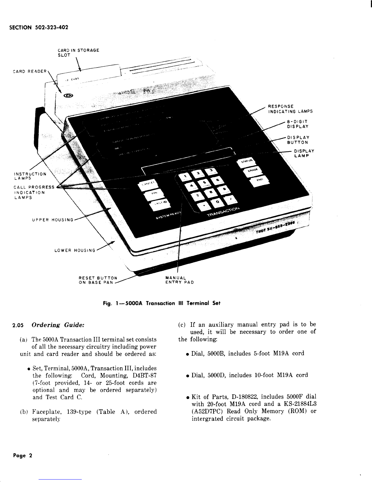
TRANSACTION Ill
FACEPLATE ORDERING GUIDE
FACEPLATE CODE ICOLOR GUIDE I
139 A-’
LETTERING
Standard
Instruction
139 B-*
LETTERING ISUFFIX ICOLOR I
-1oo Avocado
I-108 ITeak I
I-109 \Walnut I
-111 Gold
Blank -112 Orange
!-113 IBrown I
-114 Red
I-115 Blue
I-118 IBlack ]
*Add appropriate color suffix.
(d) If a5000A printer is to be provided, it
must be ordered separately and will be
shipped with the following items:
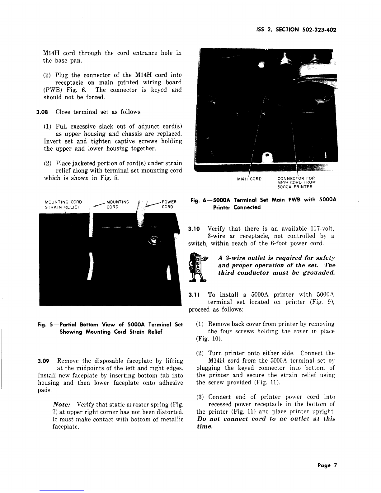
●Cord, M14H, to interconnect with 5000A
terminal set, (3-foot provided, 10-foot available)
●Housing Spacer, to be used when 5000A
terminal set is placed on top of printer (Fig.
10)
●Test Cards Dand E. (Test Card Dis
provided for use with the 51OOBMTransaction
set and will not be used with this terminal.)
●Cord, Power, KS-14532L30, 6-foot long
Note: Power cords with right angle plugs
are available in other lengths as follows:
824013262 (P-40J326) 1-1/2 foot
824013270 (P-40J327) 2foot
824013288 (P-40J328) 4foot
824013296 (P-40J329) 6foot
824010995 (P-40J099) 12 foot
3. INSTALLATION
3.o1 Verify that aTransaction Network polled
access line has been installed and terminated
in a150A Channel Service Unit (CSU) Fig. 2.
IVote; The mounting cord of the 5000A
terminal set must connect directly with a
150A CSU which has been tested and the
attenuator switches set for the correct signal
level. For installation and testing of the CSU,
refer to Section 590-101-000.
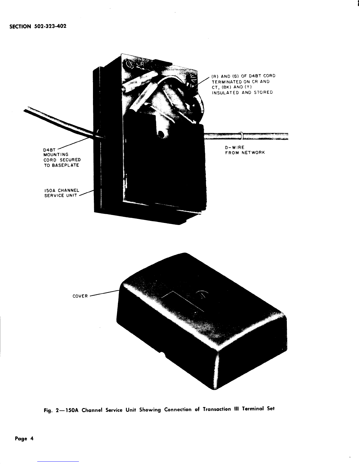
3.02 Secure the J-hook (Fig. 2) of the D4BT
mounting cord into the baseplate of the
CSU and terminate as follows:
(1)
(2)
Feed end of mounting cord under printed
wiring board (PWB) to opposite side of CSU.
Terminate tip (G) and ring (R) cord conductors
to CT and CR screw terminals, respectively,
of Csu.
(3) Insulate and store the (Y) and (BK) mounting
cord leads so they will not interfere with
wiring components of the CSU.
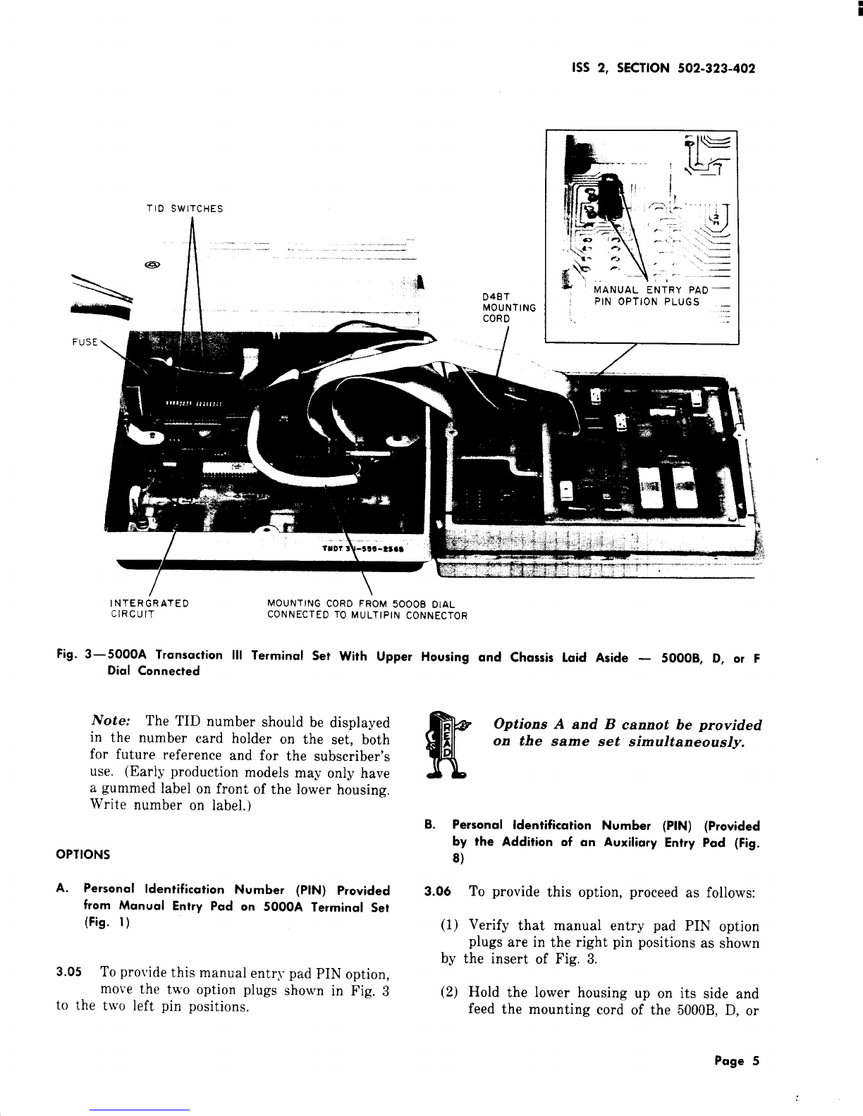
3.03
(1)
(2)
To open the 5000A terminal set, proceed as
follows:
Invert set and loosen the two captive screws
holding the upper housing and chassis.
Lay the upper housing and chassis to the
right, as shown by Fig. 3without disconnecting
any cables.
3.o4 The Terminal Identification (TID) for the
terminal being installed (number is on the
service order) should now be set on the terminal
identification switches (Fig. 3). The 4digits of
the TID are set by closing the appropriate
rocker-switches in each digit group which have
values of 1, 2, 4, and 8counting from left to right.
If front side of rocker switch is depressed, the
switch will close and the horizontal mark across
the bar is not visible. If rear side of rocker switch
is depressed, the switch will open and the horizontal
mark across the bar is visible. Only closed switches
produce a1, 2, 4, or 8(counting left to right) or
acombination thereof. See Fig. 4for example of
switches coded for TID No. 5874.
Page 3