Bellman & Symfon BE1411 Assembly instructions

Visit installer’sguide

Transmitters
Door transmitter
Push button transmitter
Telephone transmitters
Mobile phone transceiver
Baby monitor
Smoke alarms
CO alarm
Receivers
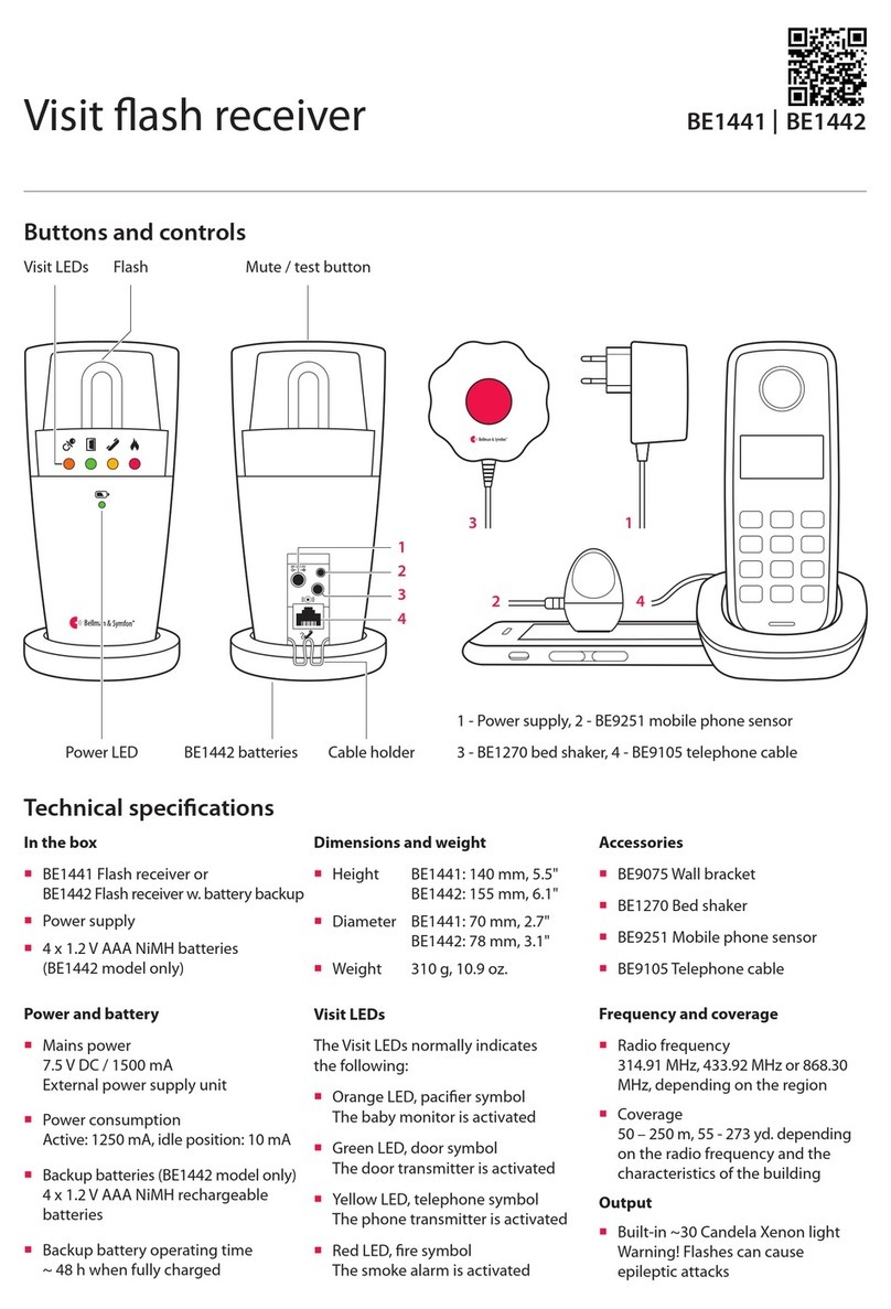
Flash receiver
Portable receiver
Pager receiver
Wrist receiver
Alarm clock receiver
Accessories
Magnetic mounting kit
Pager charger
Mobile phone sensor
Bed shaker
Flash receiver bracket
Magnetic switch
Contact mat
External microphone
External trigger cable
All you need to
know about Visit.
2

6
1
32
5
7
4
8
VISIT SYSTEM
System overview
1Door transmitter
Monitors the doorbell 2Smoke alarm
Detects smoke and re 3Baby monitor
Monitors your little one 4Mobile phone transceiver
Monitors your smart devices
Reliableandexible
TheVisit system is highly exible and can easily be
congured to cater for your client’s specic home
environment and lifestyle.
It oersdoorbell andphonedetection,babymonitoring
and re protection that meets the highest standards.
5Flash receiver
Alerts withbrightlights 6Alarm clock
Usessound,light& vibrations 7Portable receiver
Alerts with sound and light 8Pager receiver
Alerts with vibrations
Easy access to support material
Use the product QR codes with your
mobile phone or tablet to get web
access to detailed product information,
images and installation movies.QR CODE

65
Buttonsandconnections
Technicalspecications
VISITTRANSMITTERS
Visit door transmitter
Test / program buttons
Ext. trig.input
3.5 mm ext. mic. input BE9199 / BE9200
External microphone
Internal microphoneLED lights
Doorbell pushbutton
BE1411
Installation–singlesoundsource
Using the transmitter’s internal microphone
1Pull the battery tab to start the transmitter.
Clean the wall with the wet wipe and remove the protective lm from theVelcro.
2Mount the door transmitter to the left of the doorbell’s sound source, as close as possible.
You can also use the supplied screw and plug.
1 2
Max 3 cm, 1.2"
Sound source
Alternativeinstallation–single sound source
Using the external microphone accessory
1Connecttheexternalmicrophone(soldseparately)tothe transmitter.
Removethe protectivelm andattachit totheintercom’s speaker.
2Pull thebattery tab to start the transmitter. Remove the protective lm fromtheVelcro and mountthe transmitter onthe wall.
3Within2 min,pressthelowerbutton10times toturno theinternalmicrophone.TheLEDswillblink3timesinredtoconrm.
Note: Ifyouexceed2 minutes,youneedtorestartthetransmitterbyremovingthebatteries andputtingthem backinagain.
Turningthe internalmicrophonebackon
Restart the transmitter by removing the batteries and putting them back in.Within 2 minutes, press the lower button
10 times to turn the internal microphone back on.The LEDs will blink 3 times in green to conrm.
Ext. mic.
(sold separately)
1 2 3
10
In the box
BE1411Visit door transmitter
21.5V AA (LR6)
lithium or alkaline batteries
Velcro for wall mounting
Screw and wall plug
Power and battery
Battery power
21.5V AA lithium or
alkaline type batteries
Power consumption
Active < 70 mA
Idle position < 15 A
Operation time
Alkaline batteries:
~ 5 years
Lithium batteries:
~ 10 years
Frequency and coverage
Frequency: 315 MHz, 433.92 MHz or
868.3 MHz, depending on region
Coverage by region:
315 MHz: Up to 50 m (164 ft)
433 MHz: 30 – 80 m (98 - 260 ft)
868 MHz: 50 – 250 m (55 - 273 yd)
Coverage depends on the radio
frequency, building’s characteristics
and the combination of transmitters
and receivers.
Inputs
3.5 mm external microphone input
External trigger input
Accessories
The following accessories are available:
BE9199 External microphone
2.5 m, 8.2'
BE9200 External microphone
0.75 m, 2.4'
Dimensions and weight
Height: 100 mm, 4.0"
Width: 65 mm, 2.6"
Depth: 27 mm, 1.1"
Weight: 120 g, 4.2 oz. incl. batteries
Activation
The test buttons and the int. mic.
The electromagnetic detector
The external microphone accessory
The existing doorbell connected to
the external trigger input
Environment
For indoor use only
Operating temperature
0° to 35° C, 32° to 95° F
Relative humidity
15% to 90%, non-condensing

87
Usingelectromagneticdetection
The door transmitter can be set to detect electromagnetic elds emitted by electromechanical doorbells.
Here is how it’s done:
Activatingelectromagneticdetection:Move the 4th signal-switch to the up (on position).
Deactivatingelectromagneticdetection:Move the 4th signal-switch to the down (o position).
Ext. trig
Ext. trig
VISITTRANSMITTERS
Visit door transmitter BE1411
Installation– intercomandelectronicdoorbell
1Remove the protective lm from the external microphone (sold separately) and attach it to the intercom’s speaker.
Connect it to the door transmitter.
2Pull the battery tab to start the transmitter.
Clean the wall with the wet wipe and remove the protective lm from theVelcro.
3Mount the door transmitter to the left of the doorbell’s sound source, as close as possible.
Note: The intercom and doorbell must be at least 25 cm 10" apart to avoid sound interference.
Installation– intercomandmechanical doorbell
If you have an intercom and a mechanical doorbell, you may need two door transmitters, i.e. one for each sound source.
1Pull the battery tab to start each door transmitter.
Clean the wall surfaces with the wet wipe and remove the protective lms from theVelcro.
2Mount one of the door transmitters to the left of the doorbell and the other to the left of the intercom’s speaker, as close
to the sound sources as possible.
2
Ext. mic.
(sold separately)
Electronic
doorbell
Max 3 cm, 1.2"
31
On
Installation– hardwiringyourdoorbell
1Pull the battery tab to start the transmitter.
Within 2 min, press the lower button 10 times to turn o the internal microphone.The LEDs will blink 3 times to conrm.
2Remove the front cover to access the screw terminal.There are 3 connection points:
Use 1and 2to connect an active switch, like a relay with current (2–30VDC, polarity independent
or 2–24VAC, 5 - 150Hz).
Use 2and 3to connect a passive switch, like a push button.
3Put the front cover back, remove the protective lm from theVelcro and mount the door transmitter on the wall.
1 2 3
Max 3 cm, 1.2" Max 3 cm, 1.2"
1 2
10
23
1
Mechanical
doorbell

109
VISITTRANSMITTERS
Visit door transmitter
Using the doorbell or intercom
1 Press the button on the doorbell or intercom.
The LED on the transmitter lights up in green to show
that the sound is detected.
2 The greenVisit LED on the receiver lights up to show
that the radio signal was received. In addition, it starts to
sound, ash or vibrate depending on the receiver.
Note: If you have changed the signal pattern, it will react
in accordance with the table on the following spread.
Testingthe connection
Using the test button
1 Press both test buttons simultaneously on the door
transmitter.The top LED lights up in green to show that
a radio signal is being transmitted.
2 The greenVisit LED on the receiver lights up to show
that the signal was received. In addition, it starts to
sound, ash or vibrate depending on the receiver.
Note: If you have changed the signal pattern, it will react
in accordance with the table on the following spread.
1 2 1 2
1 2 3
OK
Try again
Optimizingthedoorbell detection
The next step is to teach the transmitter to recognize your doorbell.
1Press and hold button 1 until the top LED starts to blink. Release it to start the recording.
2For doorbuzzers(with continuous sound): Press and hold the doorbell for at least 8 seconds.
For doorchimes(with a "ding-dong" sound): Press the doorbell at least 8 times.
3Press button 1 on the transmitter to stop the recording. If the LED lights up in red, you need to repeat steps 1 and 2.
If you have an intercom, use button 2 and follow the steps above to record its sound.
Note: To delete all recorded sounds, press and hold button 1 and 2 simultaneously for 5 s. All radio key settings and
signal settings are kept intact.
Defaultsignal pattern
When the door transmitter is activated, the following happens:
1The LED on the transmitter lights up in green to show that it’s signalling the receiver.
2TheVisit LED on the receiver lights up in green and it starts to sound, ash or vibrate with a certain pace, called signal
pattern.The transmitter and the connected accessories determine the signal pattern.The default is as follows:
Transmitter Receiver signal pattern
Source LED LED Sound Vibration Flash
Internal microphone Green, top Green light 1door chime, low Slow Yes
External microphone Green, bottom Green blinks 2door chime, high Slow Yes
Connected doorbell Green, top 3green blinks 1doorchime, high Slow Yes
Changingthe signalpattern
The transmitter controls the signal pattern. Open the transmitter front cover and move the
signal switches according to the table below to change it:
Transmitter Receiver signal pattern
Switch Source LED Sound Vibration Flash
Int. mic. / learned signal 1 / test Green light 1door chime, low Slow Yes
Ext. mic. / learned signal 2 Green blink 2door chime, high Slow Yes
Connected doorbell 3green blinks 1doorchime, high Slow Yes
Int. mic. / learned signal 1 / test 2green blinks 2door chime low Slow Yes
Ext. mic. / learned signal 2 3green blinks 1door chime, high Slow Yes
Connected doorbell Green blinks 2doorchime, high Slow Yes
Int. mic. / learned signal 1 / test 3green blinks 1door chime, high Slow Yes
Ext. mic. / learned signal 2 2green blinks 2door chime, low Slow Yes
Connected doorbell 3orange blinks Babymelody Fast Yes
Int. mic. / learned signal 1 / test Green blinks 2door chime, high Slow Yes
Ext. mic. / learned signal 2 Green light 1door chime, low Slow Yes
Connected doorbell Orange blinks Babymelody Fast Yes
Int. mic. / learned signal 1 / test Green light 1door chime, low Slow Yes
Ext. mic. / learned signal 2 3green blinks 1door chime, high Slow Yes
Connected doorbell 2greenblinks 2door chime, low Slow Yes
Int. mic. / learned signal 1 / test Green light 1door chime low Slow Yes
Ext. mic. / learned signal 2 Greenblinks 2door chime, high Slow Yes
Connected doorbell Yellow blinks 2ringsignal,high Medium Yes
Int. mic. / learned signal 1 / test 3greenblinks 1door chime, high Slow Yes
Ext. mic. / learned signal 2 Green light 1door chime, low Slow Yes
Connected doorbell Red + orange light Emergency siren Long Yes
Int. mic. / learned signal 1 / test Green blinks 2door chime, high Slow Yes
Ext. mic. / learned signal 2 2green blinks 2door chime, low Slow Yes
Connected doorbell Redblinks Fire horn Long Yes
On
O
BE1411

1211
If Try this
TheLEDsblink in orangeeveryminute Replace the batteries. Only use 1.5V AA (LR6) lithium or alkaline batteries.
Thetransmitter LEDsblink in orange
every second There are other competing sound sources around the door transmitter. Switch
them o or turn them down.
Disconnect the external microphone accessory to make sure it is not faulty.
The transmitter LED lights up when I
press the doorbell or intercom – but
the receiver is not activated
Check the transmitter batteries and the receiver batteries and connections.
Move the receiver closer to the transmitter to make sure it’s within radio range.
Check that the door transmitter and the receiver are set to the same radio key.
For more information, see Changing theradiokey.
The transmitter LED doesn’t light up
when I ring the doorbell or intercom Ring the doorbell while moving the transmitter closer and further away from
the sound source.The ideal distance is less than 3 cm.
Program the transmitter to recognize the doorbell sound. See Programming.
If thesignalvaries a lotinstrengthortone,changeto electromagneticdetection.
If the door transmitter is still not activated, press and hold button 1 and 2
simultaneously for 5 s to clear the recorded sounds and repeat the steps above.
The receiver is activated for no
apparent reason There is probably anotherVisit system installed nearby that triggers your
system. Change the radio key on all units, see Changingtheradiokey.
Changingthe radiokey
If yourVisit system is activated for no reason, there is probably a nearby system that triggers yours. In order to avoid radio
interference, you need to change the radio key on all units.The radio key switches are located under the transmitter cover.
Here is how you change the radio key:
1Open the transmitter front cover and move any radio key switch to the up (on position) to
change the radio key. By default, all radio key switches are positioned down (o).
2Press and hold the test/function button on the receiver until the green and yellowVisit LEDs
blink alternately. Release the button.
3Press both test buttons simultaneously on the transmitter within 30 s to send the new radio key.
4AllVisit LEDs on the receiver blink 5 times to show that the radio key has been changed. It then returns to normal mode.
Note: AllVisit units must be set to the same radio key in order to operate as a group.
5
Troubleshooting
1 2 3 4
On
O
BE1411
VISITTRANSMITTERS
Visit door transmitter

1413
Buttonsand connections
In the box
BE1420Visit pushbutton transmitter
with pre-mounted PX28G/PX28M
6V alkaline battery
Lanyard with safety clasp
Adhesive tape, screws and plugs
Power and battery
Battery type
16V PX28G/PX28M alkaline or
16V PX28L lithium
Power consumption
Active < 35 mA
Idle position < 0.05 A
Operation time
Alkaline battery ~ 2 years
Lithium battery ~ 5 years
Frequency and coverage
Frequency: 315 MHz, 433.92 MHz or
868.3 MHz, depending on region
Coverage by region:
315 MHz: Up to 50 m (164 ft)
433 MHz: 30 – 80 m (98 - 260 ft)
868 MHz: 50 – 250 m (55 - 273 yd)
Coverage depends on the radio
frequency, building’s characteristics
and the combination of transmitters
and receivers.
Maintenance and cleaning
Maintenance free
Clean with a dry cloth
Do not use household cleaners,
aerosol sprays, solvents, alcohol,
ammonia or abrasives
VISITTRANSMITTERS
Visit push button transmitter
Status LED
Pre-mountedbattery
Radio key switches Hole for lanyardFront button
Technicalspecications
AdhesivetapeFrontcover
Signal switches
2holemarkings
Usingit asacallerbutton
The transmitter can be worn around your neck and
be used as a wireless caller button.
Here is how you use it:
1Attach the lanyard to the transmitter.
2Hang the transmitter around your neck.
Usingit asadoorbell
The transmitter can also be used as a wireless doorbell. Here is how you set it up:
Mounting with screws
1Carefully remove the transmitter front cover and make two holes on the markings.
2Fix the unit to the wall using the supplied screws and put the cover back on.
2
1 2
21
A B
www.bellman.com
Bellman Visit 868 Pushbutton transmitter
Model: BE1420
Frequency 868,3 MHz
Battery: 1 x 6V
Made in P.R.C. by Bellman & Symfon AB, Sweden
1
Mounting with adhesive tape
1Attach the adhesive tape to the back of the transmitter.
Clean the wall with the wet wipe and remove the protective lm from the tape.
2Mount the unit in a weather protected area by the front door.
BE1420
Dimensions and weight
Height: 66 mm, 2.6"
Width: 48 mm, 1.9"
Depth: 23 mm, 0.9"
Weight: 50 g, 1.8 oz. incl. battery
Activation
Via the front button
Environment
For indoor use and outdoor use
in a protected location.Will not
withstand water or rain. (IP42)
Operating temperature
-10° to 40° C, 14° to 104° F
Relative humidity
15% to 90%, non-condensing

1615
Defaultsignal pattern
Transmitter Receiver signal pattern
LED LED Sound Vibration Flash
Green light Green light 1doorchime, low Slow Yes
Changingthe signalpattern
Changing the signal pattern is easy. Just open the transmitter front cover and move signal switches
no. 8, 9 and 0 according to the table below:
Transmitter Receiver signal pattern
Switch LED Sound Vibration Flash
Green light 1doorchime, low Slow Yes
2green blinks 2doorchime, low Slow Yes
3green blinks 1doorchime, high Slow Yes
Green blinks 2doorchime, high Slow Yes
Orange light Baby melody Fast Yes
Orange blinks Baby melody Fast Yes
Yellow light 1ring signal, low Medium Yes
Yellow blinks 2ring signal, high Medium Yes
Testingthe connection
Using the front button
1 Press the front button on the transmitter.The LED lights up
in green to show that a radio signal is being transmitted.
2The greenVisit LED on the receiver lights up to show that
the signal was received. In addition, it starts to sound, ash
or vibrate with a certain pace, called signal pattern.
The transmitter determines the signal pattern and the
default is as follows:
1 2
VISITTRANSMITTERS
Visit push button transmitter
On
O
Changingthe radiokey
If yourVisit system is activated for no reason, there is probably a nearby system that triggers yours. In order to avoid radio
interference you need to change the radio key on all units.The radio key switches are located under the transmitter cover.
Here is how you change the radio key:
1Remove the transmitter front cover and move any radio key switch to the up (on position)
to change the radio key. By default, all radio key switches are positioned down (o).
2Press and hold the test/function button on the receiver until the green and yellowVisit LEDs
blink alternately. Release the button.
3Press the front button on the transmitter within 30 seconds to send the new radio key.
4AllVisit LEDs on the receiver blink 5 times to show that the radio key has been changed. It then returns to normal mode.
Note: AllVisit units must be set to the same radio key in order to operate as a group.
RADIO KEY
On
O
Troubleshooting
If Try this
Thetransmitter LEDlightsup in yellow
whenIpressthebutton The battery is nearly depleted. Replace it with an alkaline PX28A or a lithium
PX28L type battery.
The transmitterLED doesn’t light up
whenIpressthebutton Check that the battery is positioned correctly.
Replace the battery with an alkaline PX28A or a lithium PX28L type battery.
The transmitter LED lights up in green
but the receiver is not activated Check the receiver batteries and connections.
Move the receiver closer to the transmitter to make sure it’s within radio range.
Check that the units are set to the same radio key, see Changingtheradiokey.
The receiver is activated for no
apparent reason There is probably anotherVisit system installed nearby that triggers your
system. Change the radio key on all units, see Changingtheradiokey.
RADIO KEY SIGNAL
1 2 3 4
BE1420
5

1817
VISITTRANSMITTERS
Visit telephone transmitter
Using a mobile phone
1 Use for instance a mobile phone to call the landline
telephone.The top LED on the transmitter lights up in
green to show that an incoming call is detected.
2 The yellowVisit LED on the receiver lights up to show
that the radio signal was received. In addition, it starts to
sound, ash or vibrate depending on the receiver.
Note: If you have changed the signal pattern, it will react
in accordance with the table on the following spread.
Setting upthetransmitter
1Remove the battery pull tab to start the unit.
Clean the wall with the wet wipe and remove the protective lm from theVelcro.
2Mount the transmitter on the wall.You can also use the supplied screw and plug.
3Connect the telephone adapter as shown below.
Note: The appearance of the adapter may dier with territory.
12
Testingthe connection
Using the test button
1 Press both test buttons simultaneously on the telephone
transmitter.The top LED lights up in green to show that
a radio signal is being transmitted.
2 The yellowVisit LED on the receiver lights up to show
that the signal was received. In addition, it starts to
sound, ash or vibrate depending on the receiver.
Note: If you have changed the signal pattern, it will react
in accordance with the table on the following spread.
3
1 2 1 2
BE1431
Buttonsand connections
Test / program buttons 3.5 mm ext. trig. BE9023 Magnetic switchBE9026 Contact matLED lights
Doorbell pushbutton
BE9253
Pre-mountedtelephonecord
BE9250Mobilephonesensor with battery*2.5mmext.trig.
Technicalspecications
In the box
BE1431Visit telephone transmitter
21.5V AA alkaline batteries
Telephone cord and adapter
Screw and wall plug
Power and battery
Battery power: 21.5V AA lithium or
alkaline type batteries
Power consumption: Active < 70 mA,
Idle position < 15 A
Operation time:
Alkaline batteries ~ 5 years
Lithium batteries ~ 10 years
Environment
For indoor use only
Temperature: 0° to 35° C, 32° to 95° F
Relative humidity: 15% to 90%,
non condensing
Accessories
BE9023 Magnetic switch
BE9026 Contact mat
BE9250 Mobile phone sensor*
BE9253 Ext. trig. cable, 3.5 mm
Frequency and coverage
Frequency: 315 MHz, 433.92 MHz or
868.3 MHz, depending on region
Coverage by region:
315 MHz: Up to 50 m (164 ft)
433 MHz: 30 – 80 m (98 - 260 ft)
868 MHz: 50 – 250 m (55 - 273 yd)
Coverage depends on the radio
frequency, building’s characteristics
and the combination of transmitters
and receivers.
Dimensions and weight
Height: 100 mm, 4.0"
Width: 65 mm, 2.6"
Depth: 27 mm, 1.1"
Weight: 120 g, 4.2 oz. incl. batteries
Activation
The test buttons
A landline telephone
A smartphone or tablet via the
mobile phone sensor*
Acontact mat or magnetic switch
A doorbell connected to the ext trig
Inputs
RJ11 analogue telephone input
2.5 mm external trigger input
3.5 mm external trigger input
*Not availableonallmarkets.

2019
VISITTRANSMITTERS
Visit telephone transmitter
Changingthe radiokey
If yourVisit system is activated for no reason, there is probably a nearby system that triggers yours. In order to avoid radio
interference you need to change the radio key on all units.The radio key switches are located under the transmitter cover.
Here is how you change the radio key:
1Open the transmitter front cover and move any radio key switch to the up (on position) to
change the radio key. By default, all radio key switches are positioned down (o).
2Press and hold the test/function button on the receiver until the green and yellowVisit LEDs
blink alternately. Release the button.
3Press both test buttons simultaneously on the transmitter within 30 seconds to send the new radio key.
4AllVisit LEDs on the receiver blink 5 times to show that the radio key has been changed. It then returns to normal mode.
Note: AllVisit units must be set to the same radio key in order to operate as a group.
5
Troubleshooting
On
O
If Try this
TheLEDsblink in orangeeveryminute Replace the batteries. Only use 1.5V AA (LR6) lithium or alkaline batteries.
ThetransmitterLEDlights upingreen
but the receiver doesn’t respond Check the the transmitter batteries and the receiver batteries and connections.
Move the receiver closer to the transmitter to make sure it’s within radio range.
Check that the units are set to the same radio key, see Changingtheradiokey.
The transmitter LED doesn’t light up
when the phone rings or when an
accessory is triggered
Press the test buttons on the transmitter. If the LED lights up in green, check all
connections. If the LED doesn’t light up in green, replace the batteries. Only use
1.5V AA (LR6) lithium or alkaline batteries.
The transmitter LED doesn’t light up
when I press the test buttons Replace the batteries. Only use 1.5V AA (LR6) lithium or alkaline batteries. If the
LED still doesn’t light up, contact your retailer for service information.
The receiver is activated for no
apparent reason There is probably anotherVisit system installed nearby that triggers your
system. Change the radio key on all units, see Changingtheradiokey.
1 2 4
BE1431
RADIO KEY
On
O
3
Defaultsignal pattern
When the telephone transmitter is activated by an incoming call or a triggered accessory, the following happens:
1The LED on the transmitter lights up to show that it’s signalling the receiver.
2TheVisit LED on the receiver lights up and it starts to sound, ash or vibrate with a certain pace, called signal pattern.
The transmitter and the connected accessories determine the signal pattern.The default is as follows:
Transmitter Receiver signal pattern
Source LED LED Sound Vibration Flash
Landline phone Green, top Yellow light 1ring signal, low Medium Yes
Mobilephonesensor*Green, top Yellow blinks 2ring signal, high Medium Yes
Other accessory Green, bottom Green light 1doorchime,low Slow Yes
Changingthe signalpattern
The transmitter controls the signal pattern. Open the transmitter front cover and move the
signal switches according to the table below to change it:
Transmitter Receiver signal pattern
Switch Source LED Sound Vibration Flash
Landline phone / test button Yellow light 1ring signal, low Medium Yes
Mobile phone sensor*Yellow blinks 2ring signal, high Medium Yes
Other accessory Green light 1doorchime,low Slow Yes
Landline phone / test button Yellow light 1ring signal, low Medium Yes
Mobile phone sensor*Yellow blinks 2ring signal, high Medium Yes
Other accessory 2green blinks 2doorchime, low Slow Yes
Landline phone / test button Yellow light 1ring signal, low Medium Yes
Mobile phone sensor*Yellow blinks 2ring signal, high Medium Yes
Other accessory 3yellow blinks 1ringsignal,high Medium Yes
Landline phone / test button Yellow light 1ring signal, low Medium Yes
Mobile phone sensor*Yellow blinks 2ring signal, high Medium Yes
Other accessory 2orangeblinks Baby melody Fast Yes
Landline phone / test button 2yellow blinks 2ring signal, low Medium Yes
Mobile phone sensor*Yellow light 1ring signal, low Medium Yes
Other accessory 3orangeblinks Baby melody Fast Yes
Landline phone / test button 2yellow blinks 2ring signal, low Medium Yes
Mobile phone sensor*Orangeblinks Babymelody Fast Yes
Other accessory Green blinks 2doorchime, high Slow Yes
Landline phone / test button Orange blinks Baby melody Fast Yes
Mobile phone sensor*3yellow blinks 1ring signal, high Medium Yes
Other accessory 2green blinks 2doorchime, low Slow Yes
Landline phone / test button 3yellow blinks 1ring signal, high Medium Yes
Mobile phone sensor*2yellow blinks 2ring signal, low Medium Yes
Other accessory Greenblinks 2doorchime,high Slow Yes
On
O
*Not availableonallmarkets.

2221
Buttonsand connections
Technicalspecications
Test / program buttons
Powersupply Landlinetelephone Mobile phone
Doorbell
3.5 mm ext. trig. Magnetic switchContact matLED lights
VISITTRANSMITTERS
VisitMobilephonetransceiver BE1433
Installing theapp
1Turn on Bluetooth®
Swipedown fromthetop ofthescreenandtap
theBluetoothicon.
3
4
100%
Music
10:02 IThu, 26 Sep
WiFi Sound Bluetooth Flight mode
2Install the Visit app
Download the BellmanVisitapp from the
App Store® or Google Play™ and follow the
setup instructions.
Installing thetransmitter
3Mount it
Remove the cover from theVelcro on the back of the
transceiver and mount it on the wall.
4Turn it on
Pull the battery tab to start the transceiver.The
indicators light up in green to show that it is on.
5Connect it
Connect the USB cable to the power adapter. Then plug
the adapter into a wall outlet. If you have a landline
telephone, connect it to the telephone jack using the
supplied splitter.
6Test the mobile phone
Have someone call your mobile.The yellow LED on the
Visit receiver blinks and it starts to ash, sound or vibrate
(depending on the receiver).
7Test the landline phone
Call your landline phone.The yellow LED on theVisit
receiver lights up and it starts to ash, sound or vibrate
(depending on the receiver).
5
6
7
The appearance of your
phone splitter may dier.
In the box
BE1433 Mobile phone transceiver
Power adapter and power cable
21.5V AA alkaline batteries
Pre-mounted telephone cord
Telephone splitter
Screw and wall plug
Compatibility
iOS11 and later
Android 6 and later
iPhone 6S and later
Modern Android devices
Power and battery
Mains power: 5V DC / 1000 mA
Backupbatteries:21.5VAAAlkaline
Accessories
BE9023 Magnetic switch
BE9026 Contact mat
BE9253 Ext. trigger cable, 3.5 mm
Connectivity
RJ11 analogue telephone input
3.5 mm ext. trig port for accessories
Power supply jack
Bluetooth 5.0
Frequency and coverage
ISM frequency: 868.3 MHz
ISM coverage: Up to 250 m (275 yd)
Bluetooth frequency:
2400 – 2483.5 MHz
Bluetooth coverage: Up to 250 m
Dimensions and weight
Height: 100 mm, 4.0"
Width: 65 mm, 2.6"
Depth: 27 mm, 1.1"
Weight: 120 g, 4.2 oz. incl. batteries
Activation
A mobile device via Bluetooth
A landline telephone
Acontact mat or magnetic switch
Adoorbellconnectedto theext.trig
The test buttons
Environment
For indoor use only.
Temperature: 0 to 35 °C, 32 to 95 °F
Humidity:15%to90%,noncondensing

2423
VISITTRANSMITTERS
Usingthe app
Once you have installed theVisit app, you will start to
receiveVisit notications on your mobile phone. In
addition, yourVisit receiver will alert for mobile calls and
messages. Controlling your system from the app is easy.
Here’s what you can do:
Manage notications
Enable, disable or delete a notication
with an easy tap.
Control your devices
Get an overview of your connected devices
and tap +to add a new one.
View history
See your latest notications, sorted by
date and time.
Learn more
Tap Userguidein the menu to learn more
about the application features.
Noise
My notifications
Defaultsignal pattern
WhentheMobile phonetransceiverisactivatedby an
incomingcallor atriggeredaccessory,thefollowinghappens:
1The LED on the transceiverlights up to show that it’s
signalling the receiver.
2TheVisit LED on the receiver lights up and it starts to
sound, ash or vibrate with a certain pace, called signal
pattern.The transceiver and the connected accessories
determine the signal pattern.The default is as follows:
Changingthe signalpattern
Thetransceiver controlsthe signalpattern. Openthe
transceiverfrontcoverand move thesignal switches, see
ChangingsignalpatternonBE1431orintheappUserguide.
Changingthe radiokey
If yourVisit system is activated for no reason, there is
probably anearby system that triggers yours.This means
that youneed to changethe radio key onall units, see
Changingthe radiokeyonBE1431orintheapp Userguide.
VisitMobilephonetransceiver BE1433
Troubleshooting
Most problems with the Mobile phone transceiver can be solved quickly by following the advice below.
If Try this
The transceiver LEDs blink
in amber when the unit is
triggered
This means that the backup battery level is low. Try the following:
Change batteries
Open the transceiver cover and replace the batteries. Only use 1.5V AA (LR6) batteries.
Connect to power
Make sure that the power cable is connected to the power adapter, and the adapter is
connected to mains.
ThetransceiverLEDs blinkin
redeveryminute This means that the backup batteries are almost depleted.Try the following:
Change batteries
Open the transceiver cover and replace the batteries. Only use 1.5V AA (LR6) batteries.
Connect to power
Make sure that the power cable is connected to the power adapter, and the adapter is
connected to mains.
TheVisit receiver doesn’t
respond when the landline
phone rings or when a
connected accessory is
triggered
This could have multiple causes. Press and release both test buttons on the transceiver to
send a signal to yourVisit receiver.
If the transceiver LED lights up in green, try the following:
1.Check the battery power
Make sure that the batteries on yourVisit receiver are not depleted and that it is
connected to mains power (if applicable).
2.Check the radio key
Make sure that the units are set to the same radio key, see Changingtheradio key.
3.Move withinVisit range
Move theVisit receiver closer to the transceiver to make sure it’s withinVisit radio range.
If the transceiver LED doesn’t light up in green, try the following:
Check the power and the batteries
Make sure that the power adapter is connected and that the backup batteries are not
depleted. If the LED still doesn’t light up in green, contact your retailer for information on
warranty and service.
If the Visit receiver responds when you press the test buttons:
This means that the connection between your accessory and the transceiver is faulty.
Check the connections
Make sureall cables betweenthetransceiverandthe accessoriesareproperly connected.
The mobile phone doesn’t
receive a notication when a
Visit transmitter is triggered
This could have multiple causes. First make sure that theVisit app is open or running in
the background.Then check that the notication card for the transmitter or connected
accessory on the app home screen is activated on your device, see User guide > Manage
notications for detailed information.
Check the connection between the transmitter and the Mobile phone transceiver
Press and release the test button/s on the transmitter.The Mobile phone transceiver
bottom LED lights up in green to conrm that the units are communicating.
Transceiver Receiver signal pattern
Source LED LED Sound Vibration Flash
Landline phone Green, top Yellow light 1ring signal, low Medium Yes
Mobilephone Green, top Yellow blinks 2ring signal, high Medium Yes
Accessory Green, bottom Green light 1doorchime,low Slow Yes

2625
If Try this
If the LED doesn’t light up check the transmitter user manual for further assistance.
If the mobile still doesn’t receive notications, try the following:
Check the connection between the Mobile phone transceiver and
mobile device
Press and release both test buttons on the transceiver to send a notication
to your mobile device.The transceiver’s top LED lights up in green to conrm.
If theLEDdoesn’tlight up:
This means that the batteries are depleted, and you need to replace them.
If theLEDlights up butthenotication doesn’tappearon yourmobiledevice:
Start by checking the Bluetooth connection on the app home screen.
If the top right house icon is red, try the following:
1.Check that Bluetooth is activated on your mobiledevice
Swipe to open the Notication Center/Panel and tap the Bluetooth icon to
turn it on.
2.Turn Bluetooth o andon
Swipe to open the Notication Center/Panel and tap the Bluetooth icon to turn
Bluetooth o and then on.
3.Force-quit the BellmanVisit app
Try to force-quit the app and open it again. Please note that it’s not enough to
just close the app.
4.Check that the Phone transceiver is listed as a paired device in the Bluetooth
settings menu
If it is not listed, open Menu > My devices, tap“Replace”on the Mobile phone
transceiver device card and follow the instructions to pair the transceiver
to the mobile.
TheVisit receiver doesn’t
respond whenthe mobile
phone rings orreceives a
message.
This could have multiple causes. First make sure that theVisit app is open or
running in the background.Then check that the mobile phone notication cards
for message and phone call on the app home screen are activated on your device,
see User guide > Manage notications for detailed information. Press and release
both test buttons on the transceiver.
If the transceiver LED doesn’t light up in green, try the following:
Check the power and the batteries
Make sure that the power adapter is connected and that the backup batteries
are not depleted. If the LED still doesn’t light up in green, contact your retailer for
information on warranty and service.
If the Visit receiver responds and a notication appears on your
mobile device:
Checkthemobile device'ssettings
There are some settings which can prevent calls and messages from being
forwarded to the transceiver.
If Try this
If the Visit receiver responds and the notication doesn’t appear on your
mobile device:
ChecktheBluetooth connection
Start by checking the Bluetooth connection on the app home screen. If the
top right house icon is red, try the following:
1.Check that Bluetooth is activated on your mobile
Swipe to open the Notication Center/Panel and tap the Bluetooth icon
to turn it on.
2.Turn Bluetooth o andon
Swipe to open the Notication Center/Panel and tap the Bluetooth icon to
turn Bluetooth o and then on.
3.Force-quit the BellmanVisit app
Try to force-quit the app and open it again. Please note that it’s not enough
to just close the app.
4.Check compatibility with third-party app
Do you use third-party applications as Facebook Messenger, Skype,WhatsApp,
WeChat, or Google Hangouts? Depending on model, your mobile phone may
in some cases fail to forward notications for calls and messages to yourVisit
system.We suggest that you test the app by asking someone to call or send a
message via the app. If yourVisit receiver doesn’t respond (even though the
mobile phone message- and phone call notication cards are activated), the
third-party app may be incompatible.
If the Visit receiver doesn’t respond, try the following:
1.Check the battery power
Make sure that the batteries on yourVisit receiver are not depleted and/or
that it is connected to mains power.
2.Check the radio key
Make surethat the unitsareset tothesame radio key,seeChanging radiokey.
3.Move withinVisit range
Move theVisit receiver closer to the transceiver to make sure it’s within
Visit radio range.
TheVisit receiver is activated
for no apparent reason There could be anotherVisit system installed nearby that triggers your system.
Change the radio key on allVisit units to avoid radio interference, see Changing
theradiokey.
VISITTRANSMITTERS
VisitMobilephonetransceiver BE1433

2827
Using your voice
1 Stand by the baby monitor and make some noise.The
top LED lights up in green to show that the sound was
detected.
2 The orangeVisit LED on the receiver lights up to show
that the radio signal was received. In addition, it starts to
sound, ash or vibrate depending on the receiver.
Note: If you have changed the signal pattern, it will react
in accordance with the table on the following spread.
Setting upthebaby monitor
1Remove the battery pull tab to start the unit.
(You can press and hold both test buttons for 3 seconds to turn it on/o.)
2Place the baby monitor on the bedside table or mount it on the wall using the supplied screw and plug.
The recommended distance is 0.5 – 2 m, always out of reach from the child.
1 2
Testingthe connection
Using the test button
1 Press both test buttons simultaneously on the baby
monitor.The top LED lights up in green to show that a
radio signal is being transmitted.
2 The orangeVisit LED on the receiver lights up to show
that the signal was received. In addition, it starts to
sound, ash or vibrate depending on the receiver.
Note: If you have changed the signal pattern, it will react
in accordance with the table on the following spread.
1 2 1 2
BE1491
Buttonsand connections
Technicalspecications
VISITTRANSMITTERS
Visit baby monitor
Test / settings
BE9026 contact mat
Alerts youifyourchildleavesthebed.
3.5 mm ext. trig. MicrophoneLED lights
Always make sure the baby monitor is out of the child’s reach.
Never place the baby monitor in the child’s cot or playpen.
In the box
BE1491Visit baby monitor
21.5V AA alkaline batteries
Pre-mounted table stand
Screw and wall plug
Power and battery
Battery power
21.5V AA lithium or alkaline
type batteries
Power consumption
Active < 70 mA
Idle position < 400 A
Operation time
Alkaline batteries ~ 6 months
Lithium batteries ~ 1 year
Environment
For indoor use only
Operating temperature
0° to 35° C, 32° to 95° F
Relative humidity
15% to 90%, non-condensing
Frequency and coverage
Frequency: 315 MHz, 433.92 MHz or
868.3 MHz, depending on region
Coverage by region:
315 MHz: Up to 50 m (164 ft)
433 MHz: 30 – 80 m (98 - 260 ft)
868 MHz: 50 – 250 m (55 - 273 yd)
Coverage depends on the radio
frequency, building’s characteristics
and the combination of transmitters
and receivers.
Dimensions and weight
Height: 100 mm, 4.0"
Width: 65 mm, 2.6"
Depth: 27 mm, 1.1"
Weight: 118 g, 4.2 oz. incl. batteries
Activation
The internal mic. and test buttons
The contact mat accessory
Settings
Sensitivity: 65 dB, 75 dB, 85 dB
Delay: 30 sec, 10 sec, 1 sec
Accessories
BE9026 Contact mat

3029
Changingthe radiokey
If yourVisit system is activated for no reason, there is probably a nearby system that triggers yours. In order to avoid radio
interference, you need to change the radio key on all units.The radio key switches are located under the monitor cover.
Here is how you change the radio key:
1Carefully remove the table stand and open the front cover on the baby monitor. Move any
radio key switch to the up (on position) to change the radio key.
2Press and hold the test/function button on the receiver until the green and yellowVisit LEDs
blink alternately. Release the button.
3Press both test buttons simultaneously on the baby monitor within 30 s to send the new radio key.
4AllVisit LEDs on the receiver blink 5 times to show that the radio key has been changed. It then returns to normal mode.
Note: AllVisit units must be set to the same radio key in order to operate as a group.
Troubleshooting
If Try this
TheLEDsblink in orangeeveryminute Replace the batteries. Only use 1.5V AA (LR6) lithium or alkaline batteries.
The baby monitor LED lights up in
green but the receiver is not activated Check the baby monitor batteries and the receiver batteries and connections.
Move the receiver closer to the baby monitor to make sure it’s within range.
Check that the units are set to the same radio key, see Changingtheradiokey.
The baby monitor LED doesn’t light up
even though the baby is crying Move the baby monitor closer to the baby or increase the microphone
sensitivity, see Adjustingthesettings.
Note: Always make sure the baby monitor is out of the child’s reach.
Never place the baby monitor in the child’s crib or playpen.
Thebabymonitoris activatedtooeasily Reduce the sensitivity or move the baby monitor further away from the crib, see
Adjustingthesettings.
Thebabymonitoris activatedtooearly Increase the delay. For more information, see Adjusting thesettings.
Thebabymonitoris activatedtoolate Reduce the delay, see Adjusting thesettings.
The receiver is activated for no
apparent reason There is probably anotherVisit system installed nearby that triggers your
system. Change the radio key on all units, see Changingtheradiokey.
5
1 2 3 4
On
O
BE1491
VISITTRANSMITTERS
Defaultsignal pattern
When the baby monitor is activated by the baby’s voice or the contact mat, the following happens:
1The LED on thebaby monitor lights up ingreen to showthat it is signalling the receiver.
2TheVisit LED on the receiver lights up in orange and it starts to sound, ash or vibrate with a certain pace, called signal
pattern.The baby monitor and the contact mat accessory determine the signal pattern.The default is as follows:
Baby monitor Receiver signal pattern
Source LED LED Sound Vibration Flash
Baby voice Green, top Orange light Baby melody Fast Yes
Contact mat Green, bottom Green light 1doorchime, low Slow Yes
Changingthe signalpattern
If you have more than one child, you can set a uniqueVisit LED pattern for each baby monitor. Just
open the front cover and move any signal switch to the up (on position) and make sure the other
switches are down (o).
Baby monitor Receiver signal pattern
Switch Source LED Sound Vibration Flash
Baby monitor 1 Orange light Baby melody Fast Yes
Contact mat 1 Green light Baby melody Fast Yes
Baby monitor 2 2orange blinks Baby melody Fast Yes
Contact mat 2 2green blinks Baby melody Fast Yes
Baby monitor 3 3orange blinks Baby melody Fast Yes
Contact mat 3 3orange blinks Baby melody Fast Yes
Baby monitor 4 Orange blinks Baby melody Fast Yes
Contact mat 4 Orange blinks Baby melody Fast Yes
On
O
Visit baby monitor
Adjustingthesettings
The buttons for sensitivity and delay are located on the left side of the baby monitor.When you press the button, the
corresponding LED color shows the current setting.Then press repeatedly to adjust the setting.
If the baby monitor is not activated when the baby cries – increase the sensitivity.
If the baby monitor is activated too easily – reduce the sensitivity.
If the baby monitor is activated too early or too late – adjust the delay.
Sensitivity settings Delay settings
65 dB Red 30 s Red
75 dB Orange 10 s Orange
85 dB Green 1 s Green

3231
BE1481
Installing thesmokealarm
1Remove the mounting bracket from the smoke alarm by turning it counter-clockwise and insert the supplied
batteries to start the unit.
2Fix the mounting bracket to the ceiling using the supplied screws and plugs. Make sure it’s located at least 50 cm,
(20") from walls and other obstructions, see Location andpositioning. For alternative mounting options see p 36.
3Fit the smoke alarm to the bracket by turning it clockwise until is snaps into place.
Testingthe connection
1Press and hold the smoke alarm test button until the alarm
sounds and the status indicator starts to blink. The smoke
alarm transmits a radio signal to the receiver.
2The redVisit LED on the receiver lights up to show that the
signal was received. In addition, it starts to sound, ash or
vibrate depending on the receiver.
Note: The smoke alarm will stop sounding shortly after the
button is released and the receiver will time out within 1 min.
1 2
12 3
Location andpositioning
Fitthesmokealarms inthecenterofthe ceilingoutside
thebedrooms,atleast 50cm, (20")fromanywall.If the
bedrooms are in dierent areas of the house, separate
smoke alarms are recommended. In multi-storey
properties,installat leastonesmoke alarmoneach oor.
Avoid kitchens, replaces or garages, as cooking
fumes and car exhaust may cause false alarms.The
smoke alarm should not be installed in damp spaces,
close to fans, etc. or in agricultural buildings.
=Minimum
=Additionalsmoke alarm
VISITTRANSMITTERS
Visit smoke alarm – optothermal
Buttonsand controls
Technicalspecications
Horn Mounting plateTest button
Statusindicator 21.5VAALithiumbatteries
In the box
BE1481Visit smoke alarm
21.5V AA Lithium batteries
2Screws and plugs
Mounting plate
User manual
Power and battery
Battery type
21.5V AA Energizer Lithium L91
Power consumption
Active < 75 mA
Idle < 15 A
Operation time
Minimum 5 years
Frequency and coverage
Radio frequency
868.3 MHz
Coverage: Up to 200 m(218 yd.)
clear line of sight.The range is
reduced by walls, large objects and
other radio transmitters such as
televisionsandmobile phones.
Environment
For indoor use only
Operating temperature
4° to40° C, 39° to 104° F
Relative humidity
15% to95% R.H.,
non-condensing
Size and weight
Diameter: 120 mm, 4.2"
Depth: 37 mm, 1.3"
Weight: 165 g, 5.8 oz. incl. batteries
Sensor type
Opticalsmokeand thermaldetection
Min85dB(A)@3m,Frequency:3.2 kHz
Activation
Via the test button
Via the smoke detector
Smoke sensitivity: 0.115 – 0.168 dB/m
Via the thermal sensor
Heatsensitivity: 54°to 70°C,
129°to158° F

3433
BE1481
Changingthe radiokey
If yourVisitsystem isactivatedfornoreason,thereis probablya nearbysystemthattriggers yours.Inordertoavoidradio
interference,youneedto changetheradiokeyonallunits.Theprocedurediersdependingon yoursystemsetup.
Systemswithdierent typesoftransmitters
Start by changing the radio key on all other transmitters in the system by moving any of the radio key switches see the
corresponding user manual Note: All transmitters must be set to the same radio key to operate as a group
Step 1: Change the radio key on the BE1481 Smoke alarm
1Remove one of the batteries to turn o the smoke alarm and wait at least 30 s. Press and hold the test button as you
insert the battery again. Continue pressing the test button until the status indicator starts to ash. Now, release the
button.The status indicator will ash rapidly to show that the smoke alarm is ready to receive the new radio key.
2Press the test button on any other transmitter within 25 s to transmit the new radio key.
3The smoke alarm status indicator emits a steady light to show that the radio key has been received. Press the test button
on the smoke alarm to save the new radio key and exit the programming mode.
Steg 2: Change the radio key on the Visit receiver
1Press and hold the test button on the receiver until the green and yellowVisit LEDs blink alternately. Release the button.
2Press the test button on any transmitter within 25 s to transmit the new radio key.
3AllVisit LEDs on the receiver blink 5 times to show that the radio key has been changed.
21 3
21 3
5
VISITTRANSMITTERS
Visit smoke alarm – optothermal
If Try this
NothinghappenswhenI press
thesmokealarmtest button Check that the batteries are inserted correctly.
Replace the smoke alarm batteries. Only use AA Energizer lithium L91 batteries.
Check the age of the unit, see the“Replace by”label on the unit.
The smoke alarm beeps whenI
pressthetest button,butthe
Visitreceiver isnot responding
Check the smoke alarm batteries and theVisit receiver batteries and connections.
MovetheVisitreceiverclosertothesmoke alarm tomake sureit’swithinradiorange.
Check that the units are set to the same radio key, see Changingtheradiokey.
TheVisit receiver is activated for
no apparent reason Check if smoke or steam from the kitchen or bathroom causes the false alarm.
CheckiftheVisitLEDsignals forlowbattery.Ifso,changethesmoke alarm batteries.
If the problem persists, there is probably anotherVisit system nearby that triggers
yours. Change the radio key on all units, see Changingtheradio key.
Check if there is another system nearby on broadcast mode.
Thesmokealarmbeepsfornoreason Removecontaminationfromcobwebsordust.Iftheproblempersists,replacethe unit.
Signalpattern
The smoke alarm status indicator blinks in red once every 50 s to show that it is working correctly.
Depending on the cause of the alarm, the signal patterns are as follows:
Smoke alarm Receiver signal pattern
Cause Status LED Sound Visit LED Sound Vibration Flash
Smoke Blinking in red Blinking in red Fire alarm Long Yes
Heat Blinking in red Blinking in red Fire alarm Long Yes
Low battery 1 blink / 50 s 1 chirp / 50 s Blinking in red – – –
Faultyunit 1 blink / 50 s 1 chirp / 50 s – – – –
Usingbroadcast
If youwant thesmokealarmsignalto betransmittedto all Visitreceivers within radiorange, you canactivate broadcast
mode.Thiswilloverride theradiokey settings.
To activate broadcast
Press the test button three times in quick succession.The smoke alarm chirps and blinksthree times to conrm that
broadcastisactivated. Pleasenotethat lowbatterywarningswillonly betransmittedto receiverswith thesameradiokey.
Note: In broadcast mode, the alarm cannot be activated with the test button. Use smoke detector aerosol spray.
To deactivate broadcast
Press the smoke alarm test button three times in quick succession.The smoke alarm emits a steady sound and light for 2
seconds to conrm that broadcast is deactivated.The smoke alarm has now returned to the latest stored radio key.
Silencefunction
Using the silence function
In case of a nuisance alarm, press and hold the test button for 2 s to silence it temporarily. The status indicator blinks in
red every 16 s to conrm. For safety reasons, the silence mode stops automatically after 10 minutes.
Testand maintenance
Test the smoke alarm and radio connection regularly, preferably each week, e.g. during cleaning, but at least once per
month. Always test it immediately after any holidays or other extended periods of absence. Clean it with a damp cloth.
After changing battery, vacuum clean with a soft brush. Do not paint over the smoke alarm.

3635
BE9175
VISIT ACCESSORIES
Visit accessory
Magneticmounting kit
For easy installation of smoke alarms
Themagneticmount kit oersaquick and easyalterna-
tive to traditional screws and plugs. It consists of a self-
adhesiveplate thatyouxto theceiling andaself-adhesive
magnetic plate that you attach to your smoke alarm.
Installation procedure
1Removethe protectivelm fromthenon-magneticplate.
2Mount the plate on the ceiling and hold for 10 s.
3Remove the protective lm from the magnetic plate
and attach it to the smoke alarm. Hold for 10 s.
4Place the smoke alarm on the ceiling plate.
Note: The mounting kit is not suitable for vinyl
wallpapers, anti-adhesive coatings, silicone-
coated orTeon-coated surfaces.The diameter
of the smoke alarm cannot be less than 70 mm.
Technical specications
Diameter 70 mm
Weight 25 g
Color White
Environment For indoor use only
1 2
3 4
10s
10s
VISITTRANSMITTERS
Visit smoke alarm – optothermal
Changingthe radiokey
Systemswithonly BE1481Smokealarm
Step 1: Change the radio key on the BE1481 Smoke alarm
1Remove one of the batteries to turn o the smoke alarm and wait at least 30 s. Press and hold the test button as you
insert the battery again and continue holding it until the status LED goes from slow to rapid ashes. Release the button
to enter the programming mode.
2The smoke alarm is reset to the default radio key 0 and the status LED lights up to conrm.
3Within4 s, press and hold the test button until the LED goes out to select the next radio key. Radio key 1 is now selected
and the status LED lights up to conrm. Follow this procedure to advance to the next radio key.There are 9 radio keys
available. If you continue beyond radio key 9, the unit will reset to radio key 0.
4After 4 s, the smoke alarm automatically exits the programming mode and the LED goes out to conrm.
Note: Follow the steps above to change the radio key on all BE1481 smoke alarms in yourVisit system.
Steg 2: Change the radio key on the Visit receiver
1Press and hold the test button on the receiver until the green and yellowVisit LEDs blink alternately. Release the button.
2Press the test button on any transmitter within 25 s to transmit the new radio key.
3AllVisit LEDs on the receiver blink 5 times to show that the radio key has been changed.
2
13
21 3
Don’trelease the buttonuntil
theLED ashes rapidly.
Flashes Lightsup Goes out
Pressand holduntil the LED goes
outto selectthe next radio key.
Radio key0 is selected.The
LEDlights up to conrm.
5

3837
Setting upthesmoke alarm
1Remove the front cover by rotating it fully backwards and connect the battery to the battery snaps to start the unit.
The alarm will chirp during startup.
2Mark the location of the screw holes and x the smoke alarm to the ceiling using the supplied screws and plugs. Mount
it at least 30 cm, (12") from walls and other obstructions, see Locationandpositioningbelow.
3Put the cover back on the smoke alarm by pressing gently until it snaps into place.
Testingthe connection
1Press and hold the smoke alarm test button until the alarm
sounds.The smoke alarm transmits a radio signal to the
receiver.
2The redVisit LED on the receiver lights up to show that the
signal was received. In addition, it starts to sound, ash or
vibrate depending on the receiver.
Note: The smokealarm will stop soundingshortly after the
buttonisreleasedandthe receiverwilltimeoutwithin40s.
1 2
BE1551
1 2 3
Location andpositioning
Fitthesmokealarms inthecenterofthe ceilingoutside
the bedrooms, at least30 cm fromany wall.If the
bedrooms are in dierent areas of the house, separate
smoke alarms are recommended. In multi-storey
properties,installat leastonesmoke alarmoneach oor.
Avoid kitchens, replaces or garages, as cooking
fumes and car exhaust may cause false alarms.The
smoke alarm should not be installed in damp spaces,
close to fans, etc. or in agricultural buildings.
=Minimum
=Additional
Overview
In the box
BE1551Visit smoke alarm
19V alkaline battery
2screws and plugs
User manual
Power and battery
Battery type
9V alkaline battery
Power consumption
Idle position < 15 A
Battery life
Minimum 3 years
Size and weight
Height: 118 mm, 4.6"
Width: 140 mm, 5.5"
Depth: 42 mm, 1.6"
Weight: 200 g, 7 oz. incl. battery
Sensor type
Ionization smoke detection
Audible alarm
Min 85 dB(A) @ 3m (10'), 2.6 kHz
Activation
Via the test button
Via the built-in smoke detector
Technicalspecications
VISITTRANSMITTERS
Visit smoke alarm – ionization
Frequency and coverage
Radio frequency
868.3 MHz
Coverage: Up to 200 m(218 yd.), clear
line of sight. Itdepends onthe building’s
characteristics and radio conditions.
Environment
For indoor use only
Operating temperature
4° to 40° C, 39° to 104° F
Relative humidity
15% to 95% RH, non-condensing
Smoke sensitivity
Meets the BS EN 14604:2005 standard
Signal horn
Battery
Test button
Front cover Radio button
Radio LED
Status LED Sensor2screw holes
Other manuals for BE1411
10
This manual suits for next models
16
Table of contents
Other Bellman & Symfon Home Automation manuals

