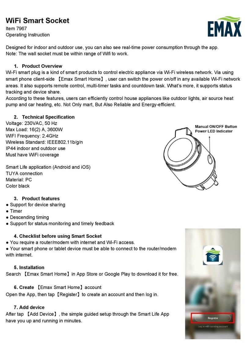
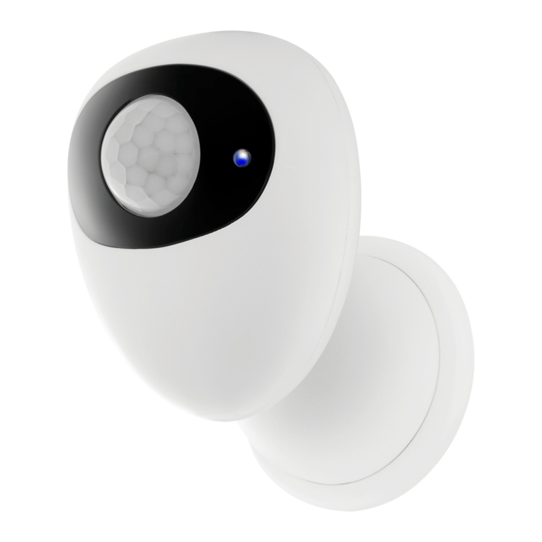
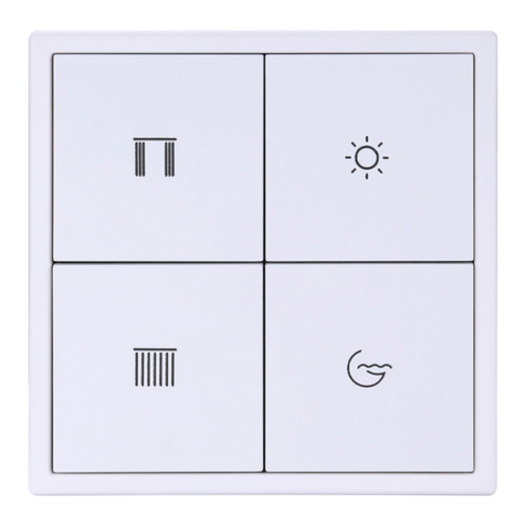
Bellman & Symfon Visit Assembly instructions

Visit installer’s guide

Transmitters
Door transmitter 5
Push button transmitter 11
Telephone transmitter 15
Baby monitor 19
Smoke alarm 23
Receivers
Flash receiver 27
Portable receiver 31
Pager receiver 35
Wrist receiver 39
Alarm clock receiver 43
Accessories
Pager charger 47
Mobile phone sensor 49
Bed shaker 51
Flash receiver bracket 52
Magnetic switch 53
Contact mat 53
External microphone 54
External trigger cable 54
All you need to
know about Visit.
21

6
1
32
5
7
4
8
VISIT SYSTEM
System overview
1Door transmitter
Monitors the doorbell
2Smoke alarm
Detects smoke and re
3Baby monitor
Monitors your little one
4Telephone transmitter
Monitors phones & tablets
Reliable and exible
The Visit system is highly exible and can easily be
congured to cater your client’s specic home
environment and lifestyle.
It oers doorbell and phone detection, baby monitoring
and re protection that meets the highest standards.
5Flash receiver
Alerts with bright lights
6Alarm clock
Uses sound, light & vibrations
7Portable receiver
Alerts with sound and light
8Pager receiver
Alerts with vibrations
Easy access to support material
Use the product QR codes with your
mobile phone or tablet to get web
access to detailed product information,
images and installation movies.
QR CODE
43

Buttons and connections
In the box
BE1411 Visit door transmitter
2 x 1.5 V AA alkaline batteries
Velcro for wall mounting
Screw and wall plug
Power and battery
Battery power
2 x 1.5 V AA lithium or alkaline
type batteries
Power consumption
Active < 70 mA
Idle position < 15 μA
Operation time
Alkaline batteries ~ 5 years
Lithium batteries ~ 10 years
Environment
For indoor use only
Operating temperature
15° to 35° C, 59° to 95° F
Relative humidity
5% to 95%, non-condensing
Frequency and coverage
Frequency: 314.91 MHz, 433.92 MHz
or 868.30 MHz, depending on region
Coverage: 50 - 250 m, 55 - 273 yd.
depending on the radio frequency
and the building’s characteristics
Accessories
The following accessories are available:
BE9199 External microphone 2.5 m
BE9200 External microphone 0.75 m
Dimensions and weight
Height: 100 mm, 4.0"
Width: 65 mm, 2.6"
Depth: 27 mm, 1.1"
Weight: 120 g, 4.2 oz. incl. batteries
Activation
The test buttons and the int. mic.
The electromagnetic detector
The external microphone accessory
The existing doorbell connected to
the external trigger input
Inputs
3.5 mm external microphone input
External trigger input
Technical specications
VISIT TRANSMITTERS
Visit door transmitter
Test / program buttons
Ext. trig. input
3.5 mm ext. mic. input BE9199 / BE9200
External microphone
Internal microphone
Installation – single sound source
1Remove the battery pull tab to start the unit.
Clean the wall with the wet wipe and remove the protective lm from the Velcro.
2Mount the transmitter to the left of the doorbell sound source, as close as possible.
You can also use the supplied screw and plug.
12
LED lights
Installation – intercom and electronic doorbell
1Remove the protective lm from the external microphone (sold separately) and attach it to the intercom speaker.
Connect the external microphone to the door transmitter ext. mic. input.
2Remove the battery pull tab to start the unit.
Clean the wall with the wet wipe and remove the protective lm from the Velcro.
3Mount the transmitter to the left of the doorbell sound source, as close as possible.
You can also use the supplied screw and plug.
2
Ext. mic.
Electronic
doorbell
Max 3 cm, 1.2"
Max 3 cm, 1.2"
31
Doorbell push button
BE1411
Sound source
65

Clearing the recorded sounds
To clear all recorded sounds, press and hold button 1 and 2 simultaneously for 5 seconds.
Note: This will clear the recorded sounds and the transmitter will return to factory settings, but the radio key settings and
signal settings are kept intact.
Using electromagnetic detection
The transmitter can be set to detect electromagnetic elds generated by electric doorbells. Here is how it’s done:
Open the transmitter front cover and move signal switch no. 4 to the up = on position to activate
electromagnetic detection. To deactivate it, move the signal switch back to the down = o position.
Using accessories
Using an external microphone
The external microphone can be used when the sound source is located too far away from the internal microphone or
when you for instance need individual notications from the doorbell and intercom.
Connecting an accessory to the external trigger input
Remove the front cover to access the screw terminal. There are three connection points.
Use connection points 1and 2to connect an active switch like a relay with current.
Note: The current must be 2 – 30 VDC, polarity independent or 2 – 24 VAC 5 – 150Hz.
Use connection points 2and 3to connect a passive mechanical switch like a doorbell push button.
Installation – intercom and mechanical doorbell
If you have an intercom and a mechanical doorbell, you may need two door transmitters, i.e. one for each sound source.
1Pull the battery pull tab to start each door transmitter.
Clean the wall surface with the wet wipe and remove the protective lm from the Velcro.
2Mount one of the transmitters to the left of the doorbell and the other to the left of the intercom speaker, as close to the
sound sources as possible.
Programming the transmitter
The door transmitter is programmed from the start to recognize the majority of doorbells and intercoms. If the doorbell
signal varies signicantly in strength or tone, you might need to teach it to recognize the sound of your specic doorbell.
Here is how you program the transmitter:
1Press and hold button 1 until the top LED starts to blink. Release it to start the recording.
2Ring the doorbell at least ve times. Pause 1 – 2 seconds between each press. The recording lasts for 5 minutes and ends
automatically. You can stop it manually by pressing button 1.
3When it’s nished, the LED lights up in green to conrm that it was successful. If the LED is red, see Troubleshooting.
4Ring the doorbell. The top LED on the transmitter lights up in green to conrm that it recognizes the sound.
You can record the sound of the intercom using button 2 by repeating the steps above.
VISIT TRANSMITTERS
Visit door transmitter
1 2
Using the doorbell or intercom
1 Press the button on the doorbell or intercom.
The LED on the transmitter lights up in green to show
that the sound is detected.
2 The green Visit LED on the receiver lights up to show
that the radio signal was received. In addition, it starts to
sound, ash or vibrate depending on the receiver.
Note: If you have changed the signal pattern, it will react in
accordance with the table on the following spread.
Testing the connection
Using the test button
1 Press both test buttons simultaneously on the door
transmitter. The top LED lights up in green to show that
a radio signal is being transmitted.
2 The green Visit LED on the receiver lights up to show
that the signal was received. In addition, it starts to
sound, ash or vibrate depending on the receiver.
Note: If you have changed the signal pattern, it will react in
accordance with the table on the following spread.
1 2 1 2
Max 3 cm, 1.2" Max 3 cm, 1.2"
Mechanical
doorbell
On
123
OK
Try again
x 5
1 2 3
BE1411
87

If Try this
The LEDs blink in orange every minute Replace the batteries. Only use 1.5 V AA (LR6) lithium or alkaline batteries.
The transmitter LEDs blinks in orange
every second
There are other competing sound sources around the door transmitter. Switch
them o or turn them down.
Disconnect the external microphone accessory to make sure it is not faulty.
The transmitter LED lights up when I
press the doorbell or intercom – but
the receiver is not activated
Check the the transmitter batteries and the receiver batteries and connections.
Move the receiver closer to the transmitter to make sure it’s within radio range.
Check that the door transmitter and the receiver are set to the same radio key.
For more information, see Changing the radio key.
The transmitter LED doesn’t light up
when I ring the doorbell or intercom
Ring the doorbell while moving the transmitter closer and further away from
the sound source. The ideal distance is less than 3 cm.
Program the transmitter to recognize the doorbell sound. See Programming.
If the signal varies a lot in strength or tone, change to electromagnetic detection.
If the door transmitter is still not activated, press and hold button 1 and 2
simultaneously for 5 s to clear the recorded sounds and repeat the steps above.
The receiver is activated for no
apparent reason
There is probably another Visit system installed nearby that triggers your
system. Change the radio key on all units, see Changing the radio key.
Changing the radio key
If your Visit system is activated for no reason, there is probably a nearby system that triggers yours. In order to avoid radio
interference, you need to change the radio key on all units. The radio key switches are located under the transmitter cover.
Here is how you change the radio key:
1Open the transmitter front cover and move any radio key switch to the up = on position to
change the radio key. (By default, all radio key switches are positioned down = o. )
2Press and hold the test/function button on the receiver until the green and yellow Visit LEDs
blink alternately. Release the button.
3Press both test buttons simultaneously on the transmitter within 30 s to send the new radio key.
4All Visit LEDs on the receiver blink 5 times to show that the radio key has been changed. It then returns to normal mode.
Please note: All Visit units must be set to the same radio key in order to operate as a group.
x 5
VISIT TRANSMITTERS
Visit door transmitter
Troubleshooting
1 2 3 4
Default signal pattern
When the door transmitter is activated, the following happens:
1The LED on the transmitter lights up in green to show that it’s signalling the receiver.
2The Visit LED on the receiver lights up in green and it starts to sound, ash or vibrate with a certain pace, called signal
pattern. The transmitter and the connected accessories determine the signal pattern. The default is as follows:
Transmitter Receiver signal pattern
Source LED LED Sound Vibration Flash
Internal microphone Green, top Green light 1 x door chime, low Slow Yes
External microphone Green, bottom Green blinks 2 x door chime, high Slow Yes
Connected doorbell Green, top 3 x green blinks 1 x door chime, high Slow Yes
Changing the signal pattern
The transmitter controls the signal pattern. Open the transmitter front cover and move the
signal switches according to the table below to change it:
Transmitter Receiver signal pattern
Switch Source LED Sound Vibration Flash
Int. mic. / learned signal 1 / test Green light 1 x door chime, low Slow Yes
Ext. mic. / learned signal 2 Green blink 2 x door chime, high Slow Yes
Connected doorbell 3 x green blinks 1 x door chime, high Slow Yes
Int. mic. / learned signal 1 / test 2 x green blinks 2 x door chime low Slow Yes
Ext. mic. / learned signal 2 3 x green blinks 1 x door chime, high Slow Yes
Connected doorbell Green blinks 2 x door chime, high Slow Yes
Int. mic. / learned signal 1 / test 3 x green blinks 1 x door chime, high Slow Yes
Ext. mic. / learned signal 2 2 x green blinks 2 x door chime, low Slow Yes
Connected doorbell 3 x orange blinks Baby melody Fast Yes
Int. mic. / learned signal 1 / test Green blinks 2 x door chime, high Slow Yes
Ext. mic. / learned signal 2 Green light 1 x door chime, low Slow Yes
Connected doorbell Orange blinks Baby melody Fast Yes
Int. mic. / learned signal 1 / test Green light 1 x door chime, low Slow Yes
Ext. mic. / learned signal 2 3 x green blinks 1 x door chime, high Slow Yes
Connected doorbell 2 x green blinks 2 x door chime, low Slow Yes
Int. mic. / learned signal 1 / test Green light 1 x door chime low Slow Yes
Ext. mic. / learned signal 2 Green blinks 2 x door chime, high Slow Yes
Connected doorbell Yellow blinks 2 x ring signal, high Medium Yes
Int. mic. / learned signal 1 / test 3 x green blinks 1 x door chime, high Slow Yes
Ext. mic. / learned signal 2 Green light 1 x door chime, low Slow Yes
Connected doorbell Red + orange light Emergency siren Long Yes
Int. mic. / learned signal 1 / test Green blinks 2 x door chime, high Slow Yes
Ext. mic. / learned signal 2 2 x green blinks 2 x door chime, low Slow Yes
Connected doorbell Red blinks Fire horn Long Yes
On
O
On
O
BE1411
109

Using it as a caller button
The transmitter can be worn around your neck and
be used as a wireless caller button.
Here is how you use it:
1Attach the lanyard to the transmitter.
2Hang the transmitter around your neck.
Using it as a doorbell
The transmitter can also be used as a wireless doorbell. Here is how you set it up:
Mounting with screws
1Carefully remove the transmitter front cover and make two holes on the markings.
2Fix the unit to the wall using the supplied screws and put the cover back on.
Buttons and connections
In the box
BE1420 Visit push button transmitter
with pre-mounted alkaline battery
Lanyard with safety clasp
Adhesive tape, screws and plugs
Power and battery
Battery type
1 x 6 V PX28A alkaline or
1 x 6 V PX28L lithium
Power consumption
Active < 35 mA
Idle position < 0.05 μA
Operation time
Alkaline battery ~ 2 years
Lithium battery ~ 5 years
Frequency and coverage
Frequency
314.91 MHz, 433.92 MHz or 868.30
MHz, depending on the region
Coverage
50 - 250 m, 55 - 273 yd. depending
on the radio frequency and the
characteristics of the building
Environment
For indoor use and outdoor use
in a protected location. Will not
withstand water or rain.
Operating temperature
15° to 35° C, 59° to 95° F
Relative humidity
5% to 95%, non-condensing
Dimensions and weight
Height: 66 mm, 2.6"
Width: 48 mm, 1.9"
Depth: 23 mm, 0.9"
Weight: 50 g, 1.8 oz. incl. battery
Activation
Via the front button
Maintenance and cleaning
Maintenance free
Clean with a dry cloth
Do not use household cleaners,
aerosol sprays, solvents, alcohol,
ammonia or abrasives
VISIT TRANSMITTERS
Visit push button transmitter
Status LED
Pre-mounted battery
Radio key switches Hole for lanyard
Front button
Technical specications
Adhesive tapeFront cover
Signal switches
2 x hole markings
2
12
21
A B
www.bellman.com
Bellman Visit 868 Pushbutton transmitter
Model: BE1420
Frequency 868,3 MHz
Battery: 1 x 6V
Made in P.R.C. by Bellman & Symfon AB, Sweden
1
Mounting with adhesive tape
1Attach the adhesive tape to the back of the transmitter.
Clean the wall with the wet wipe and remove the protective lm from the tape.
2Mount the unit in a weather protected area by the front door.
BE1420
1211

Default signal pattern
Transmitter Receiver signal pattern
LED LED Sound Vibration Flash
Green light Green light 1 x door chime, low Slow Yes
Changing the signal pattern
Changing the signal pattern is easy. Just open the transmitter front cover and move signal switches
no. 8, 9 and 0 according to the table below:
Transmitter Receiver signal pattern
Switch LED Sound Vibration Flash
Green light 1 x door chime, low Slow Yes
2 x green blinks 2 x door chime, low Slow Yes
3 x green blinks 1 x door chime, high Slow Yes
Green blinks 2 x door chime, high Slow Yes
Orange light Baby melody Fast Yes
Orange blinks Baby melody Fast Yes
Yellow light 1 x ring signal, low Medium Yes
Yellow blinks 2 x ring signal, high Medium Yes
Testing the connection
Using the front button
1 Press the front button on the transmitter. The LED lights up
in green to show that a radio signal is being transmitted.
2The green Visit LED on the receiver lights up to show that
the signal was received. In addition, it starts to sound, ash
or vibrate with a certain pace, called signal pattern.
The transmitter determines the signal pattern and the
default is as follows:
1 2
VISIT TRANSMITTERS
Visit push button transmitter
Changing the radio key
If your Visit system is activated for no reason, there is probably a nearby system that triggers yours. In order to avoid radio
interference you need to change the radio key on all units. The radio key switches are located under the transmitter cover.
Here is how you change the radio key:
1Remove the transmitter front cover and move any radio key switch to the up = on position
to change the radio key. (By default, all radio key switches are positioned down = o.)
2Press and hold the test/function button on the receiver until the green and yellow Visit LEDs
blink alternately. Release the button.
3Press the front button on the transmitter within 30 seconds to send the new radio key.
4All Visit LEDs on the receiver blink 5 times to show that the radio key has been changed. It then returns to normal mode.
Note: All Visit units must be set to the same radio key in order to operate as a group.
RADIO KEY
On
O
Troubleshooting
If Try this
The transmitter LED lights up in yellow
when I press the button
The battery is nearly depleted. Replace it with an alkaline PX28A or a lithium
PX28L type battery.
The transmitter LED doesn’t light up
when I press the button
Check that the battery is positioned correctly.
Replace the battery with an alkaline PX28A or a lithium PX28L type battery.
The transmitter LED lights up in green
but the receiver is not activated
Check the receiver batteries and connections.
Move the receiver closer to the transmitter to make sure it’s within radio range.
Check that the units are set to the same radio key, see Changing the radio key.
The receiver is activated for no
apparent reason
There is probably another Visit system installed nearby that triggers your
system. Change the radio key on all units, see Changing the radio key.
RADIO KEY SIGNAL
1 2 3 4
On
O
BE1420
x 5
1413

Using a mobile phone
1 Use for instance a mobile phone to call the landline
telephone. The top LED on the transmitter lights up in
green to show that an incoming call is detected.
2 The yellow Visit LED on the receiver lights up to show
that the radio signal was received. In addition, it starts to
sound, ash or vibrate depending on the receiver.
Note: If you have changed the signal pattern, it will react in
accordance with the table on the following spread.
Buttons and connections
In the box
BE1431 Visit telephone transmitter
2 x 1.5 V AA alkaline batteries
Telephone cord and adapter
Screw and wall plug
Power and battery
Battery power
2 x 1.5 V AA lithium or alkaline
type batteries
Power consumption
Active < 70 mA
Idle position < 15 μA
Operation time
Alkaline batteries ~ 5 years
Lithium batteries ~ 10 years
Accessories
BE9251 Mobile phone sensor
BE9023 Magnetic switch
BE9024 Contact mat
BE9253 Ext. trig. cable, 3.5 mm
Inputs
RJ11 analogue telephone input
2.5 mm external trigger input
3.5 mm external trigger input
Frequency and coverage
Frequency: 314.91 MHz, 433.92 MHz
or 868.30 MHz, depending on region
Coverage: 50 - 250 m, 55 - 273 yd.
depending on the radio frequency
and the building’s characteristics
Dimensions and weight
Height: 100 mm, 4.0"
Width: 65 mm, 2.6"
Depth: 27 mm, 1.1"
Weight: 120 g, 4.2 oz. incl. batteries
Activation
The test buttons
A landline telephone
A smartphone or tablet via the
mobile phone sensor
A contact mat or magnetic switch
A doorbell connected to the ext trig
Environment
For indoor use only
Technical specications
VISIT TRANSMITTERS
Visit telephone transmitter
Test / program buttons
2.5 mm ext. trig.
Pre-mounted telephone cord
BE9251 Mobile phone sensor
Doorbell push button
3.5 mm ext. trig. BE9023 Magnetic switchBE9024 Contact mat
Setting up the transmitter
1Remove the battery pull tab to start the unit.
Clean the wall with the wet wipe and remove the protective lm from the Velcro.
2Mount the transmitter on the wall. You can also use the supplied screw and plug.
3Connect the telephone adapter as shown below.
Note: The appearance of the adapter may dier with territory.
1 2
Testing the connection
Using the test button
1 Press both test buttons simultaneously on the telephone
transmitter. The top LED lights up in green to show that
a radio signal is being transmitted.
2 The yellow Visit LED on the receiver lights up to show
that the signal was received. In addition, it starts to
sound, ash or vibrate depending on the receiver.
Note: If you have changed the signal pattern, it will react in
accordance with the table on the following spread.
3
1 2 1 2
LED lights
BE1431
1615
BE9253

Changing the radio key
If your Visit system is activated for no reason, there is probably a nearby system that triggers yours. In order to avoid radio
interference you need to change the radio key on all units. The radio key switches are located under the transmitter cover.
Here is how you change the radio key:
1Open the transmitter front cover and move any radio key switch to the up = on position to
change the radio key. (By default, all radio key switches are positioned down = o. )
2Press and hold the test/function button on the receiver until the green and yellow Visit LEDs
blink alternately. Release the button.
3Press both test buttons simultaneously on the transmitter within 30 seconds to send the new radio key.
4All Visit LEDs on the receiver blink 5 times to show that the radio key has been changed. It then returns to normal mode.
Note: All Visit units must be set to the same radio key in order to operate as a group.
x 5
VISIT TRANSMITTERS
Visit telephone transmitter
Troubleshooting
On
O
Default signal pattern
When the telephone transmitter is activated by an incoming call or a triggered accessory, the following happens:
1The LED on the transmitter lights up to show that it’s signalling the receiver.
2The Visit LED on the receiver lights up and it starts to sound, ash or vibrate with a certain pace, called signal pattern.
The transmitter and the connected accessories determine the signal pattern. The default is as follows:
Transmitter Receiver signal pattern
Source LED LED Sound Vibration Flash
Landline phone Green, top Yellow light 1 x ring signal, low Medium Yes
Mobile phone sensor Green, top Yellow blinks 2 x ring signal, high Medium Yes
Other accessory Green, bottom Green light 1 x door chime, low Slow Yes
Changing the signal pattern
The transmitter controls the signal pattern. Open the transmitter front cover and move the
signal switches according to the table below to change it:
Transmitter Receiver signal pattern
Switch Source LED Sound Vibration Flash
Landline phone / test button Yellow light 1 x ring signal, low Medium Yes
Mobile phone sensor Yellow blinks 2 x ring signal, high Medium Yes
Other accessory Green light 1 x door chime, low Slow Yes
Landline phone / test button Yellow light 1 x ring signal, low Medium Yes
Mobile phone sensor Yellow blinks 2 x ring signal, high Medium Yes
Other accessory 2 x green blinks 2 x door chime, low Slow Yes
Landline phone / test button Yellow light 1 x ring signal, low Medium Yes
Mobile phone sensor Yellow blinks 2 x ring signal, high Medium Yes
Other accessory 3 x yellow blinks 1 x ring signal, high Medium Yes
Landline phone / test button Yellow light 1 x ring signal, low Medium Yes
Mobile phone sensor Yellow blinks 2 x ring signal, high Medium Yes
Other accessory 2 x orange blinks Baby melody Fast Yes
Landline phone / test button 2 x yellow blinks 2 x ring signal, low Fast Yes
Mobile phone sensor Yellow light 1 x ring signal, low Medium Yes
Other accessory 3 x orange blinks Baby melody Fast Yes
Landline phone / test button 2 x yellow blinks 2 x ring signal, low Medium Yes
Mobile phone sensor Orange blinks Baby melody Fast Yes
Other accessory Green blinks 2 x door chime, high Slow Yes
Landline phone / test button Orange blinks Baby melody Medium Yes
Mobile phone sensor 3 x yellow blinks 1 x ring signal, high Medium Yes
Other accessory 2 x green blinks 2 x door chime, low Slow Yes
Landline phone / test button 3 x yellow blinks 1 x ring signal, high Medium Yes
Mobile phone sensor 2 x yellow blinks 2 x ring signal, low Medium Yes
Other accessory Green blinks 2 x door chime, high Slow Yes
If Try this
The LEDs blink in orange every minute Replace the batteries. Only use 1.5 V AA (LR6) lithium or alkaline batteries.
The transmitter LED lights up in green
but the receiver doesn’t respond
Check the the transmitter batteries and the receiver batteries and connections.
Move the receiver closer to the transmitter to make sure it’s within radio range.
Check that the units are set to the same radio key, see Changing the radio key.
The transmitter LED doesn’t light up
when the phone rings or when an
accessory is triggered
Press the test buttons on the transmitter. If the LED lights up in green, check all
connections. If the LED doesn’t light up in green, replace the batteries. Only use
1.5 V AA (LR6) lithium or alkaline batteries.
The transmitter LED doesn’t light up
when I press the test buttons
Replace the batteries. Only use 1.5 V AA (LR6) lithium or alkaline batteries. If the
LED still doesn’t light up, contact your retailer for service information.
The receiver is activated for no
apparent reason
There is probably another Visit system installed nearby that triggers your
system. Change the radio key on all units, see Changing the radio key.
On
O
1 2 3 4
BE1431
RADIO KEY
On
O
1817

Buttons and connections
In the box
BE1491 Visit baby monitor
2 x 1.5 V AA alkaline batteries
Pre-mounted table stand
Screw and wall plug
Power and battery
Battery power
2 x 1.5 V AA lithium or alkaline
type batteries
Power consumption
Active < 70 mA
Idle position < 400 μA
Operation time
Alkaline batteries ~ 6 months
Lithium batteries ~ 1 year
Environment
For indoor use only
Operating temperature
15° to 35° C, 59° to 95° F
Relative humidity
5% to 95%, non-condensing
Frequency and coverage
Frequency: 314.91 MHz, 433.92 MHz
or 868.30 MHz, depending on region
Coverage: 50 - 250 m, 55 - 273 yd.
depending on the radio frequency
and the building’s characteristics
Accessories
BE9024 Contact mat
Alerts you if your baby leaves the bed
Dimensions and weight
Height: 100 mm, 4.0"
Width: 65 mm, 2.6"
Depth: 27 mm, 1.1"
Weight: 120 g, 4.2 oz. incl. batteries
Activation
The internal mic. and test buttons
The contact mat accessory
Settings
Sensitivity
65 dB, 75 dB, 85 dB
Delay
30 sec, 10 sec, 1 sec
Technical specications
VISIT TRANSMITTERS
Visit baby monitor
Test / settings
BE9024 contact mat
3.5 mm ext. trig. MicrophoneLED lights
Always make sure the baby monitor is out of the child’s reach.
Never place the baby monitor in the child’s crib or playpen.
Using your voice
1 Stand by the baby monitor and make some noise. The
top LED lights up in green to show that the sound was
detected.
2 The orange Visit LED on the receiver lights up to show
that the radio signal was received. In addition, it starts to
sound, ash or vibrate depending on the receiver.
Note: If you have changed the signal pattern, it will react in
accordance with the table on the following spread.
Setting up the baby monitor
1Remove the battery pull tab to start the unit.
(You can press and hold both test buttons for 3 seconds to turn it on/o.)
2Place the baby monitor on the bedside table or mount it on the wall using the supplied screw and plug.
The recommended distance is 0.5 – 2 m, always out of reach from the child.
1 2
Testing the connection
Using the test button
1 Press both test buttons simultaneously on the baby
monitor. The top LED lights up in green to show that a
radio signal is being transmitted.
2 The orange Visit LED on the receiver lights up to show
that the signal was received. In addition, it starts to
sound, ash or vibrate depending on the receiver.
Note: If you have changed the signal pattern, it will react in
accordance with the table on the following spread.
1 2 1 2
BE1491
2019

Changing the radio key
If your Visit system is activated for no reason, there is probably a nearby system that triggers yours. In order to avoid radio
interference, you need to change the radio key on all units. The radio key switches are located under the monitor cover.
Here is how you change the radio key:
1Carefully remove the table stand and open the front cover on the baby monitor. Move any
radio key switch to the up = on position to change the radio key.
2Press and hold the test/function button on the receiver until the green and yellow Visit LEDs
blink alternately. Release the button.
3Press both test buttons simultaneously on the baby monitor within 30 s to send the new radio key.
4All Visit LEDs on the receiver blink 5 times to show that the radio key has been changed. It then returns to normal mode.
Note: All Visit units must be set to the same radio key in order to operate as a group.
VISIT TRANSMITTERS
Troubleshooting
If Try this
The LEDs blink in orange every minute Replace the batteries. Only use 1.5 V AA (LR6) lithium or alkaline batteries.
The baby monitor LED lights up in
green but the receiver is not activated
Check the baby monitor batteries and the receiver batteries and connections.
Move the receiver closer to the baby monitor to make sure it’s within range.
Check that the units are set to the same radio key, see Changing the radio key.
The baby monitor LED doesn’t light up
even though the baby is crying
Move the baby monitor closer to the baby or increase the microphone
sensitivity, see Adjusting the settings.
Note: Always make sure the baby monitor is out of the child’s reach.
Never place the baby monitor in the child’s crib or playpen.
The baby monitor is activated too easily Reduce the sensitivity or move the baby monitor further away from the crib, see
Adjusting the settings.
The baby monitor is activated too early Increase the delay. For more information, see Adjusting the settings.
The baby monitor is activated too late Reduce the delay, see Adjusting the settings.
The receiver is activated for no
apparent reason
There is probably another Visit system installed nearby that triggers your
system. Change the radio key on all units, see Changing the radio key.
Default signal pattern
When the baby monitor is activated by the baby’s voice or the contact mat, the following happens:
1The LED on the baby monitor lights up in green to show that it is signalling the receiver.
2The Visit LED on the receiver lights up in orange and it starts to sound, ash or vibrate with a certain pace, called signal
pattern. The baby monitor and the contact mat accessory determine the signal pattern. The default is as follows:
Baby monitor Receiver signal pattern
Source LED LED Sound Vibration Flash
Baby voice Green, top Orange light Baby melody Fast Yes
Contact mat Green, bottom Green light 1 x door chime, low Slow Yes
Changing the signal pattern
If you have more than one child, you can set a unique Visit LED pattern for each baby monitor. Just
open the front cover and move any signal switch to the up = on position and make sure the other
switches are down = o.
Baby monitor Receiver signal pattern
Switch Source LED Sound Vibration Flash
Baby monitor 1 Orange light Baby melody Fast Yes
Contact mat 1 Green light Baby melody Fast Yes
Baby monitor 2 2 x orange blinks Baby melody Fast Yes
Contact mat 2 2 x green blinks Baby melody Fast Yes
Baby monitor 3 3 x orange blinks Baby melody Fast Yes
Contact mat 3 3 x orange blinks Baby melody Fast Yes
Baby monitor 4 Orange blinks Baby melody Fast Yes
Contact mat 4 Orange blinks Baby melody Fast Yes
On
O
Visit baby monitor
x 5
1 2 3 4
On
O
Adjusting the settings
The buttons for sensitivity and delay are located on the left side of the baby monitor. When you press the button, the
corresponding LED colour shows the current setting. Then press repeatedly to adjust the setting.
If the baby monitor is not activated when the baby cries – increase the sensitivity.
If the baby monitor is activated too easily – reduce the sensitivity.
If the baby monitor is activated too early or too late – adjust the delay.
Sensitivity settings Delay settings
65 dB Red 30 s Red
75 dB Orange 10 s Orange
85 dB Green 1 s Green
BE1491
2221

Buttons and controls
In the box
BE1480 Visit smoke alarm
1 x 9 V alkaline or lithium battery
Mounting plate
Screws and plugs
Power and battery
Battery power
9V Duracell MN1604, Energizer 522 or
9V Ultralife U9VL-J (lithium)
Power consumption
Active < 40 mA
Idle position < 10 μA
Operation time
Alkaline battery ~ 3 years
Lithium battery ~ 6 years
Environment
For indoor use only
Operating temperature
0° to 38° C, 32° to 100° F
Relative humidity
15% to 95%, non condensing
Frequency and coverage
Frequency: 314.91 MHz, 433.92 MHz
or 868.30 MHz, depending on region
Coverage: 50 - 250 m, 55 - 273 yd.
depending on the radio frequency
and the building’s characteristics
Regulatory requirements
BE1480 complies with the smoke
alarm standard EN 14604:2005
Dimensions and weight
Height: 100 mm, 3.9"
Width: 100 mm, 3.9"
Depth: 35 mm, 1.4"
Weight: 110 g, 3.9 oz. incl. battery
Sensor type
Optothermal sensor with an audible
alarm of > 85 dB(A) @ 3m
Activation
The test button
The built-in smoke detector
The built-in temperature sensor, if
the temperature exceeds ~ 57°C.
Technical specications
VISIT TRANSMITTERS
Visit smoke alarm
Speaker Radio antennaTest button
Using smoke detector test aerosol
1Spray some of the test material into the chamber and
wait 5 – 10 seconds for the smoke alarm to beep and
transmit a radio signal to the receiver.
2 The red Visit LED on the receiver lights up to show that
the signal was received. In addition it starts to sound,
ash or vibrate depending on the receiver.
Note: The smoke alarm will beep and transmit the signal as
long as there is test aerosol inside the chamber.
Setting up the smoke alarm
1Remove the mounting plate and connect the battery to the battery snaps to start the unit. Wait for about 10 seconds
while the smoke alarm carries out a self-test. It is nished when the test button blinks once.
2Fix the mounting plate to the ceiling using the supplied screws and plugs.
Mount it at least 50 cm, (19.7") from walls and other obstructions, see Fitting the smoke alarm.
3Attach the smoke alarm to the mounting plate by turning it clockwise. Extend the radio antenna so that it points down.
1 2
Testing the connection
Using the test button
1 Press and hold the test button on the smoke alarm for
more than one second. The smoke alarm will beep and
transmit a radio signal to the receiver.
2 The red Visit LED on the receiver lights up to show that
the signal was received. In addition it starts to sound,
ash or vibrate depending on the receiver.
Note: Once you release the smoke alarm test button, the
beep will time out in a couple of seconds.
1 2 1 2
Radio key switches 1 – 6
Broadcast switch 7
Do not use switch no. 8 Battery
3
BE1480
2423

Changing the radio key
If your Visit system is activated for no reason, there is probably a nearby system that triggers yours. In order to avoid radio
interference you need to change the radio key on all units. The radio key switches are located on the back of the smoke alarm.
Here is how you change the radio key:
1Remove the mounting plate and move any of the radio key switches 1 – 6 to the up = on
position to change the radio key.
2Press and hold the test/function button on the receiver until the green and yellow Visit
LEDs blink alternately. Release the button.
3Press the test button on the smoke alarm for more than one second to send the new radio key.
4All Visit LEDs on the receiver blink 5 times to show that the radio key has been changed. It then returns to normal mode.
Note: All Visit units must be set to the same radio key in order to operate as a group. If broadcast mode is activated, all Visit
receivers will respond regardless of the radio key settings.
Troubleshooting
Most problems with the smoke alarm can be solved quickly by following the advice below.
If Try this
Nothing happens when I press the test
button
Replace the smoke alarm battery.
Use a Duracell MN1604, Energizer 522 or Ultralife U9VL-J type battery.
The smoke alarm beeps when I press
the test button, but the receiver is not
responding
Check that the smoke alarm antenna is straight and points to the oor.
Check the smoke alarm battery and the receiver batteries and connections.
Move the receiver closer to the smoke alarm to make sure it’s within radio range.
Check that the units are set to the same radio key, see Changing the radio key
The receiver is activated for no
apparent reason
Replace the battery. Use a Duracell MN1604, Energizer 522 or Ultralife U9VL-J.
If the problem persists, there is probably another Visit system nearby that
triggers yours. Change the radio key on all units, see Changing the radio key.
The receiver beeps and chirps for no
apparent reason
The smoke alarm is defective and needs to be sent for repair.
78
x 5
1 2 3 4
On
O
VISIT TRANSMITTERS
Visit smoke alarm
Default signal pattern
The smoke alarm LED blinks in red once per minute to show that it is working correctly.
Depending on the alarm, the signal patterns are as follows:
Smoke alarm Receiver signal pattern
Alarm type LED Sound LED Sound Vibration Flash
Fire detected Red blinks Fire alarm Red blinks Fire alarm Long Yes
Low battery 2 x red blinks 1 beep every min Red blink every 5 s None None None
Flat battery Red blinks 1 beep every s Red blink every 5 s 1 x re alarm Slow None
Using broadcast mode
If you want the smoke alarm signal to be transmitted to all Visit receivers within radio range, you can activate broadcast
mode. This will override the radio key settings.
Here is how you activate broadcast mode:
Move radio switch 7 on the back of the smoke alarm to the up = on position to activate broadcast mode.
Note: Activation with the test button and battery warnings will only be transmitted to units with the same radio key.
Using toast mode
To avoid false alarm when you are for instance cooking, you can temporarily reduce the smoke alarm sensitivity.
Here is how you activate toast mode:
Press the test button briey. The smoke alarm will beep and blink twice in yellow. The LED will continue to blink in red
while it’s in toast mode.
Press the test button again to deactivate toast mode. The smoke alarm will beep and blink three times in yellow.
Note: The toast mode times out in 20 minutes.
Fitting the smoke alarm
Fit the smoke alarm in the center of the ceiling outside
the bedrooms, at least 50 cm from any wall. If the
bedrooms are in dierent areas of the house, separate
smoke alarms are recommended. In multi-storey
properties, install at least one smoke alarm on each
oor.
Avoid kitchens, replaces or garages, as cooking fumes
and car exhaust may cause false alarms. The smoke
alarm should not be installed in damp spaces, close to
fans, etc. or in agricultural buildings.
Testing and maintenance
Test the smoke alarm regularly, preferably each week, e.g. during cleaning, but at least once per month. Always test it
immediately after any holidays or other extended periods of absence. Clean it with a damp cloth. After changing battery,
vacuum clean with a soft brush. Do not paint over the smoke alarm.
= Minimum, = Additional
BE1480
2625

Buttons and controls
In the box
BE1441 Flash receiver or
BE1442 Flash receiver w. battery backup
Power supply
4 x 1.2 V AAA NiMH batteries
(BE1442 model only)
Power and battery
Mains power
7.5 V DC / 1500 mA
External power supply unit
Power consumption
Active: 1250 mA, idle position: 10 mA
Backup batteries (BE1442 model only)
4 x 1.2 V AAA NiMH rechargeable
batteries
Backup battery operating time
~ 48 h when fully charged
Accessories
BE9075 Wall bracket
BE1270 Bed shaker
BE9251 Mobile phone sensor
BE9105 Telephone cable
Frequency and coverage
Radio frequency
314.91 MHz, 433.92 MHz or 868.30
MHz, depending on the region
Coverage
50 – 250 m, 55 - 273 yd. depending
on the radio frequency and the
characteristics of the building
Output
Built-in ~30 Candela Xenon light
Warning! Flashes can cause
epileptic attacks
Dimensions and weight
Height BE1441: 140 mm, 5.5"
BE1442: 155 mm, 6.1"
Diameter BE1441: 70 mm, 2.7"
BE1442: 78 mm, 3.1"
Weight 310 g, 10.9 oz.
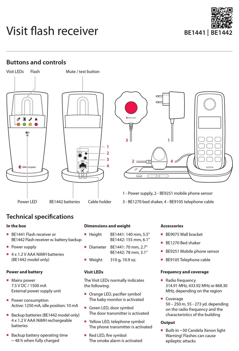
Visit LEDs
The Visit LEDs normally indicates
the following:
Orange LED, pacier symbol
The baby monitor is activated
Green LED, door symbol
The door transmitter is activated
Yellow LED, telephone symbol
The phone transmitter is activated
Red LED, re symbol
The smoke alarm is activated
Technical specications
1 2 3
VISIT RECEIVERS
Visit ash receiver
Mute / test buttonFlashVisit LEDs
BE1442 batteriesPower LED
Getting started
1Connect the power supply to the receiver and the mains outlet. Pull the battery tab on the bottom (BE1442 only.)
Place the receiver on a level surface or mount it on the wall using the wall bracket accessory (see separate instructions).
2To test the radio link you need a Visit transmitter. Press the test button/s on the transmitter.
3The receiver lights up a Visit LED and starts to ash. If a bed shaker is connected, it will vibrate.
A short press on the mute/test button repeats the last indication. If nothing happens, see Troubleshooting.
Default signal pattern
When a transmitter is activated, the ash receiver lights up a LED, ashes and the bed shaker starts to vibrate with a certain
pace. This is called signal pattern. The transmitters determine the pattern, and the default is as follows:
Transmitter Flash receiver Bed shaker
Activated source Visit LED Flash Vibration
Door transmitter / push button transmitter Green Yes Slow
Telephone transmitter / connected telephone Yellow Yes Medium
Baby monitor Orange Yes Fast
Smoke alarm Red Yes Long
Changing the signal pattern
The signal pattern can only be changed on the transmitters. See Changing the signal pattern for the relevant transmitter.
Power LED indications
When the ash receiver is connected to mains power, the power LED lights up in green.
The BE1442 model is also equipped with battery backup and the power LED indicates the following:
Power LED Status
Green light The ash receiver is connected to mains power. The backup batteries are detected.
Green blinks The ash receiver is connected to mains power. No backup batteries are detected.
Red light The ash receiver is running on battery backup.
Red blinks The backup batteries are nearly depleted.
Cable holder
BE1441 |BE1442
2827
1
2
3
4
3 1
42
1 - Power supply, 2 - BE9251 mobile phone sensor
3 - BE1270 bed shaker, 4 - BE9105 telephone cable

Changing the radio key
If your Visit system is activated for no reason, there is probably a nearby system that triggers yours. In order to avoid radio
interference, you need to change the radio key on all units. The radio key switches are located on the transmitters.
Here is how you change the radio key:
1Open the transmitter cover and move any radio key switch to the up = on position to change
the radio key. See Changing the radio key for the relevant transmitter.
2Press and hold the mute/test button on the top of the receiver until the green and yellow Visit
LEDs blink alternately. Release the button.
3Press the test button/s on the transmitter within 30 seconds to send the new radio key.
4All Visit LEDs on the receiver blink 5 times to show that the radio key has been changed. It then returns to normal mode.
Please note: All Visit units must be set to the same radio key in order to operate as a group.
1 2 3 4
x 5
VISIT RECEIVERS
Visit ash receiver
Accessories
The ash receiver can be complemented with the following accessories:
BE1270 Bed shaker
Wakes you with vibrations under the pillow or mattress.
BE9250 Mobile phone sensor
Place it on the mobile phone or tablet, and the ash
receiver will alert you of incoming calls and messages.
BE9105 Telephone cable
Use it to connect the receiver to your landline
telephone and be alerted with ashes when the phone rings.
BE9075 Wall bracket
Directing the ash
The ash receiver features a rotating top that makes it easy to direct the light. Point it for example towards a wall if you feel
that the ash is too intense. A silicone slip-on top is also available in a variety of colours (art. no. BE9164-BE9167).
If Try this
The receiver seems to be turned o Check that the power supply is connected correctly.
Charge the backup batteries for at least 24 hours (BE1442 only).
The power LED blinks in red The backup batteries are nearly depleted and the power supply is disconnected.
Connect the power supply and charge the batteries for at least 24 hours.
The power LED blinks in green The receiver detects no backup batteries. Pull the battery tab, see Getting started.
The receiver does not respond
when a transmitter is activated, but
works when I use the test button
Check the transmitter batteries and connections.
Move the receiver closer to the transmitter to make sure it’s within radio range.
Check that the receiver is set to the same radio key as the other units in the Visit
system, see Changing the radio key.
The receiver is activated for no
apparent reason
There is probably another Visit system installed nearby that triggers your system.
Change the radio key on all units, see Changing the radio key.
The ash is too bright Redirect the light by rotating the top or use a silicone slip-on top to dim the light.
On
O
Advanced programming
By using advanced programming, you can customize the signal pattern from a specic transmitter and event, displaying
the LED colour and vibration pattern of your choice. The advanced programming overrides the radio key and pairs the
units via the serial number. Please note that smoke alarms cannot be programmed for safety reasons.
Note: The transmitter must be activated as it is intended to be used in the system to generate the right signal.
This means that you can’t always use the transmitter test button (see Default signal pattern for the relevant transmitter).
Here is how you program the receiver:
1Press and hold the mute/test button on the receiver. The green and yellow Visit LEDs will start to blink alternately.
While still holding down the button, activate the desired transmitter as intended. Release the button.
2Scroll through the dierent Visit LED options by pressing the mute/test button on the receiver. Select the desired Visit
LED colour by holding down the mute/test button until the power LED goes out and lights up again.
3Scroll through the dierent vibration options by pressing the test button on the receiver (bed shaker required). Select
the desired vibration pattern by holding down the mute/test button until the power LED goes out and lights up again.
4The receiver will now show the new Visit LED colour and vibration pattern. Press the mute/test button briey to end the
demonstration. After a short while, it will return to normal mode.
Deleting the advanced programming
Follow the procedure below to delete the advanced programming.
1Hold down the mute/test button on the receiver until the green and yellow Visit LEDs blink alternately. Release the button.
2Press the mute/test button on the receiver 3 times in quick succession.
3All Visit LEDs will light up for ~2 seconds to show that it has been deleted.
Troubleshooting
Most problems with the ash receiver can be solved quickly by following the advice below.
BE1441 |BE1442
3029

Buttons and controls
In the box
BE1450 Portable receiver
4 x 1.5V LR14 batteries
Wall bracket
Screws and wall plugs
Power and battery
Mains power
7.5 V DC / 1000 mA
Optional power supply unit
Europe: BE9201, UK: BE9202
Battery power
4 x 1.5 V LR14 alkaline batteries
Operating time
2 – 3 years with alkaline batteries
Power consumption
Active: 1000 mA, idle position: 0.1 mA
Output
Adjustable sound signal
Max 93 dBA @ 1 m, frequency
range: 500 – 1000 Hz
Bed shaker outlet: 2.0 – 4.0 VDC or
Speaker outlet: 10 kΩ, 0 – 4 V
Frequency and coverage
Radio frequency
314.91 MHz, 433.92 MHz or 868.30
MHz, depending on the region
Coverage
50 – 250 m, 55 - 273 yd. depending
on the radio frequency and the
characteristics of the building
Accessories
BE1270 Bed shaker
BE9201/BE9202 Power supply unit
Dimensions and weight
Height: 165 mm, 6.5"
Width: 130 mm, 5.1"
Depth: 36 mm, 1.5"
Weight: 590 g, 20.8 oz. incl. batteries
Visit LEDs
The Visit LEDs normally indicates
the following:
Orange LED, pacier symbol
The baby monitor is activated
Green LED, door symbol
The door transmitter is activated
Yellow LED, telephone symbol
The phone transmitter is activated
Red LED, re symbol
The smoke alarm is activated
Technical specications
1 2 3
VISIT RECEIVERS
Visit portable receiver
Visit LEDs
VolumePower LED Flash signal switch
Recessions for wall bracket Battery compartment Optional power supply
BE1270 Bed shaker
Test button
BE1450 BE1452
Getting started
1Slide open the battery cover, t the batteries and close the cover again.
Place the receiver on a level surface or mount it on the wall using the wall bracket.
2To test the radio link you need a Visit transmitter. Press the test button/s on the transmitter.
3The receiver lights up a Visit LED and starts to ash and sound. If a bed shaker is connected, it will vibrate.
A short press on the test button repeats the last indication. If nothing happens, see Troubleshooting.
Default signal pattern
When a transmitter is activated, the receiver lights up a LED, sounds, ashes and the bed shaker starts to vibrate with a
certain pace. This is called signal pattern. The transmitters determine the pattern, and the default is as follows:
Transmitter Portable receiver Bed shaker
Activated source Visit LED Sound Flash Vibration
Door transmitter / push button transmitter Green Door chime Yes Slow
Telephone transmitter Yellow Ring signal Yes Medium
Baby monitor Orange Baby melody Yes Fast
Smoke alarm Red Fire horn Yes Long
Changing the signal pattern
The signal pattern can only be changed on the transmitters. See Changing the signal pattern for the relevant transmitter.
Adjusting the volume and ash
Adjust the volume to your liking using the red volume dial on the top of the receiver. It goes from 0 to 93 dBA @ 1 m with a
main frequency range of 500 – 1000 Hz. Use the ash signal switch on the back of the receiver to turn the ash o/on.
Replacing batteries
If the power LED is yellow when the receiver is activated, the batteries are nearly depleted. Here is how you replace them:
Slide open the battery cover. Replace the old batteries with four new 1.5 V LR14 alkaline batteries, see the battery
compartment for correct positioning.
Flash LEDs
BE1450 |BE1452
3231

Changing the radio key
If your Visit system is activated for no reason, there is probably a nearby system that triggers yours. In order to avoid radio
interference, you need to change the radio key on all units. The radio key switches are located on the transmitters.
Here is how you change the radio key:
1Open the transmitter cover and move any radio key switch to the up = on position to change
the radio key. See Changing the radio key for the relevant transmitter.
2Press and hold the test button located on the bottom of the portable receiver until the green
and yellow Visit LEDs blink alternately. Release the button.
3Press the test button/s on the transmitter within 30 seconds to send the new radio key.
4All Visit LEDs on the receiver blink 5 times to show that the radio key has been changed. It then returns to normal mode.
Please note: All Visit units must be set to the same radio key in order to operate as a group.
1234
x 5
VISIT RECEIVERS
Visit portable receiver
Accessories
The portable receiver can be complemented with the following accessories:
BE1270 Bed shaker
Wakes you with vibrations if anything
happens while you are asleep. Connect
it to the receiver and slide it under your
pillow or mattress.
BE9201 EU / BE9202 UK power supply
If your receiver has a xed place, you
can connect it to mains power and not
having to worry about batteries.
Connecting a speaker
On the receiver model BE1452, the bed shaker outlet is replaced with a 3.5 mm audio output that can drive an external
speaker. The speaker can be used to amplify the receiver audio signal further or to relay the audio signal to a nearby room.
BE1270
If Try this
The receiver seems to be turned o The batteries are depleted. Replace them with 4 x 1.5V LR14 alkaline batteries.
The power LED is yellow when the
receiver is activated.
The battery level is low. Replace them with 4 x 1.5V LR14 alkaline batteries.
The receiver does not respond
when a transmitter is activated, but
works when I use the test button
Check the transmitter batteries and connections.
Move the receiver closer to the transmitter to make sure it’s within radio range.
Check that the receiver is set to the same radio key as the other units in the Visit
system, see Changing the radio key.
The receiver is activated for no
apparent reason
There is probably another Visit system installed nearby that triggers your system.
Change the radio key on all units, see Changing the radio key.
The receiver is too silent Turn up the volume using the red volume dial on the top of the unit.
The receiver is not ashing Check that the ash signal switch on the back of the unit is set to the ON position.
On
O
Advanced programming
By using advanced programming, you can customize the signal pattern from a specic transmitter and event, displaying
the LED colour, sound and vibration pattern of your choice. The advanced programming overrides the radio key and pairs
the units via the serial number. Please note that smoke alarms cannot be programmed for safety reasons.
Note: The transmitter must be activated as it is intended to be used in the system to generate the right signal.
This means that you can’t always use the transmitter test button (see Default signal pattern for the relevant transmitter).
Here is how you program the receiver:
1Press and hold the test button on the receiver. The green and yellow Visit LEDs will start to blink alternately.
While still holding down the button, activate the desired transmitter as intended. The power LED on the receiver will
light up in yellow to show that you are in advanced programming mode. Release the button.
2Scroll through the dierent Visit LED options by pressing the test button on the receiver. Select the desired Visit LED
colour by holding down the test button until the power LED goes out and lights up again.
3Scroll through the dierent sound optionsby pressing the test button on the receiver. Select the desired sound by
holding down the test button until the power LED goes out and lights up again.
4Scroll through the dierent vibration options by pressing the test button on the receiver (bed shaker required).
Select the desired vibration pattern by holding down the test button until the power LED goes out and lights up again.
5The receiver will now show the new Visit LED colour, sound and vibration pattern. Press the test button briey to end the
demonstration. After a short while, it will return to normal mode.
Deleting the advanced programming
Follow the procedure below to delete the advanced programming.
1Hold down the test button on the receiver until the green and yellow Visit LEDs blink alternately. Release the button.
2Press the test button on the receiver 3 times in quick succession.
3All Visit LEDs will light up for ~2 seconds to show that it has been deleted.
Troubleshooting
BE1450 |BE1452
3433

Function button
Belt clipVisit LEDs
Battery LED
Battery eject Battery compartment
Optional safety cord with clip
Front label Battery cover
Buttons and controls
In the box
BE1470 Visit pager receiver
Safety cord with clip
Extra front label
Power and battery
Mains power
7.5 V DC 200 mA via the charger
Battery power
1.5 V AAA alkaline or
1.2 V AAA NiMH rechargeable battery
Operation time
Alkaline battery: 2 – 3 weeks
NiMH battery: ~1 week
Power consumption
Active: ≤200 mA, Idle position: ≤1 mA
Environment
For indoor use only
Operating temperature
15° to 35° C, 59° to 95° F
Relative humidity
5% to 95%, non-condensing
Frequency and coverage
Radio frequency
314.91 MHz, 433.92 MHz or 868.30
MHz, depending on the region
Coverage
50 – 250 m, 55 - 273 yd. depending
on the radio frequency and the
characteristics of the building
Accessories
BE1260 Pager charger
BE1270 Bed shaker
Dimensions and weight
Height: 86 mm, 3.4"
Width: 57 mm, 2.2"
Depth: 29 mm, 1.1"
Weight: 70 g, 2.5 oz. incl. battery
Visit LEDs
The Visit LEDs normally indicates
the following:
Orange LED, pacier symbol
The baby monitor is activated
Green LED, door symbol
The door transmitter is activated
Yellow LED, telephone symbol
The phone transmitter is activated
Red LED, re symbol
The smoke alarm is activated
Technical specications
1.5V AAA
Getting started
1Open the battery cover, t the battery and close the cover again.
Attach the pager to your belt using the belt clip. For extra security, use the supplied safety cord.
2To test the radio link you need a Visit transmitter. Press the test button/s on the transmitter.
3The pager starts to vibrate and lights up a Visit LED. If a bed shaker is connected during charging, it will vibrate.
If nothing happens, see Troubleshooting.
1 2 3
VISIT RECEIVERS
Visit pager receiver
Default signal pattern
When a transmitter is activated, the pager lights up a LED and starts to vibrate with a certain pace. This is called signal
pattern. The transmitters determine the pattern, and the default is as follows:
Activated transmitter Pager LED Pager / bed shaker vibration
Door transmitter Green Slow
Push button transmitter Green Slow
Telephone transmitter Yellow Medium
Baby monitor Orange Fast
Smoke alarm Red Long
Changing the signal pattern
The signal pattern can only be changed on the transmitters. See Changing the signal pattern for the relevant transmitter.
Changing the front label
If you want to use Visit for other purposes, the pager front label can be replaced with a customized one. Here is how it’s done:
Open the battery cover, replace the original label with the supplied extra label and close the cover again.
Replacing the battery
When the battery LED starts to blink in yellow, the battery is nearly depleted. Here is how you replace it:
Open the battery cover and press the battery eject button to remove the old battery. Insert a 1.5 V AAA alkaline battery
or a 1.2 V AAA NiMH rechargeable battery if you are using the BE1260 charger accessory.
BE1470
3635

Changing the radio key
If your Visit system is activated for no reason, there is probably a nearby system that triggers yours. In order to avoid radio
interference, you need to change the radio key on all units. The radio key switches are located on the transmitters.
Here is how you change the radio key:
1Open the transmitter cover and move any radio key switch to the up = on position to change
the radio key. See Changing the radio key for the relevant transmitter.
2Press and hold the function button on the pager until the green and yellow Visit LEDs blink
alternately. Release the button.
3Press the test button/s on the transmitter within 30 seconds to send the new radio key.
4All Visit LEDs on the pager blink 5 times to show that the radio key has been changed. It then returns to normal mode.
Please note: All Visit units must be set to the same radio key in order to operate as a group.
1 2 3 4
x 5
VISIT RECEIVERS
Visit pager receiver
Pager accessories
The pager can be complemented with the following accessories:
BE1260 Pager charger
Charges your pager during the night. Place it on the
bedside table and connect up to two bed shakers.
Please note that the pager will not vibrate when it’s
charging, but the Visit LEDs will act as usual.
BE1270 Bed shaker
Wakes you with vibrations if anything happens
while you are asleep. Connect it to the pager
charger and slide it under your pillow or mattress.
Warning! When using the pager charger ONLY USE RECHARGEABLE NiMH BATTERIES in the pager.
Non-rechargeable batteries will start to leak if the pager is placed in the charger and the battery acid will
damage the electronics. The resulting damage is not covered by warranty.
BE1260
BE1270
Advanced programming
By using advanced programming, you can customize the signal pattern from a specic transmitter and event, displaying
the LED colour and vibration pattern of your choice. The advanced programming overrides the radio key and pairs the
units via the serial number. Please note that smoke alarms cannot be programmed for safety reasons.
Note: The transmitter must be activated as it is intended to be used in the system to generate the right signal.
This means that you can’t always use the transmitter test button (see Default signal pattern for the relevant transmitter).
Here is how you program the pager:
1Press and hold the function button on the pager. The green and yellow Visit LEDs will start to blink alternately.
While still holding down the button, activate the desired transmitter as intended. The yellow battery LED on the pager
will light up to indicate that you are in advanced programming mode. Release the button.
2Scroll through the dierent Visit LED options by pressing the function button on the pager. Select the desired Visit LED
pattern by holding down the function button until the battery LED goes out and lights up again.
3Scroll through the dierent vibration options by pressing the function button on the pager. Select the desired
vibration pattern by holding down the function button until the battery LED goes out and lights up again.
4The pager will now show the new Visit LED colour and vibration pattern. Press the function button briey to end the
demonstration. After a short while, the pager will return to normal mode.
Deleting the advanced programming
Follow the procedure below to delete the advanced programming.
1Hold down the function button on the pager until the green and yellow Visit LEDs blink alternately. Release the button.
2Press the function button on the pager 3 times in quick succession.
3All Visit LEDs will light up for ~2 seconds to show that it has been deleted.
Troubleshooting
Most problems with the pager can be solved quickly by following the advice below.
If Try this
The pager seems to be turned o The battery is depleted. Replace it with a 1.5V AAA alkaline battery.
Important! If you have a pager charger; only use a rechargeable 1.2 V AAA
NiMh battery in the pager.
The battery LED blinks in yellow The battery level is low. Replace it with a 1.5V AAA alkaline battery.
Important! If you have a pager charger; only use a rechargeable 1.2 V AAA
NiMh battery in the pager.
The pager does not respond
when a transmitter is activated
Check the batteries in the transmitters.
Move the pager closer to the transmitter to make sure it’s within radio range.
Check that the pager is set to the same radio key as the other units in the Visit
system, see Changing the radio key.
The pager is activated for no
apparent reason
There is probably another Visit system installed nearby that triggers your system.
Change the radio key on all units, see Changing the radio key.
On
O
BE1470
3837
Other manuals for Visit
5
Table of contents
Other Bellman & Symfon Home Automation manuals
