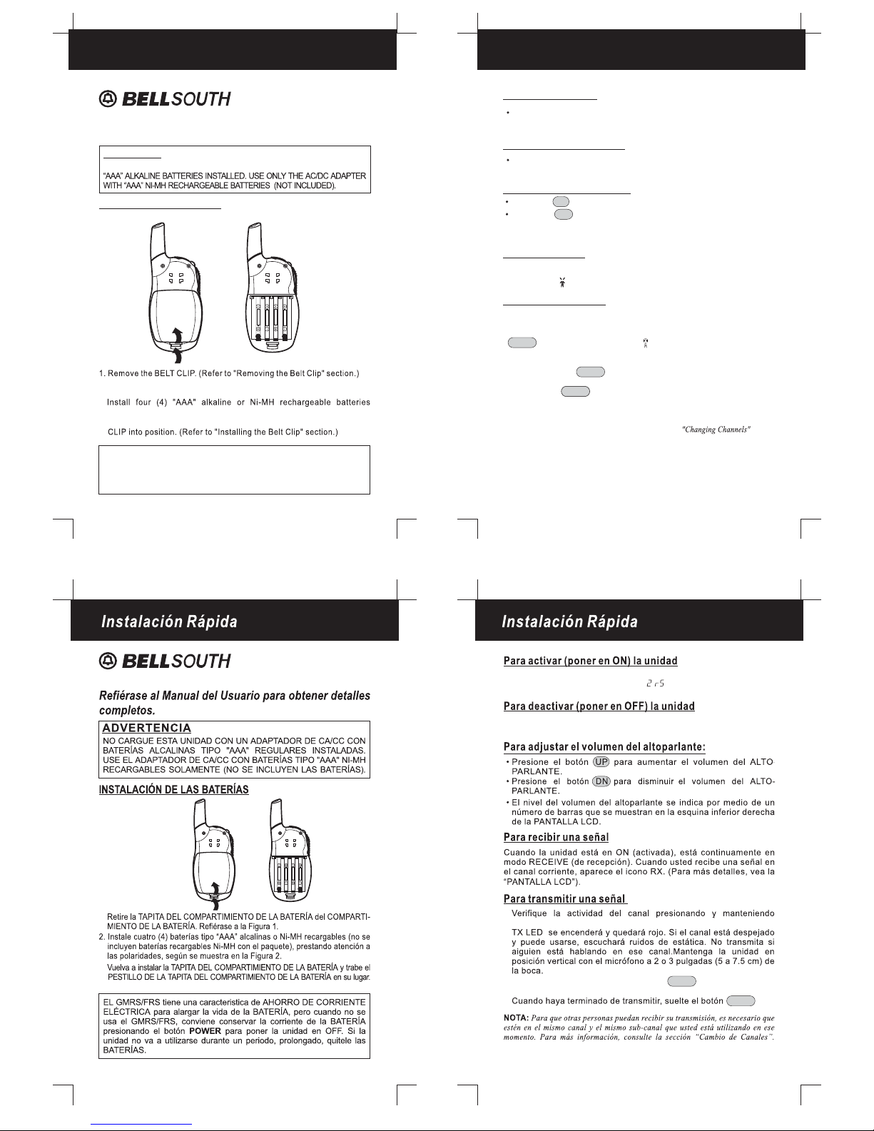
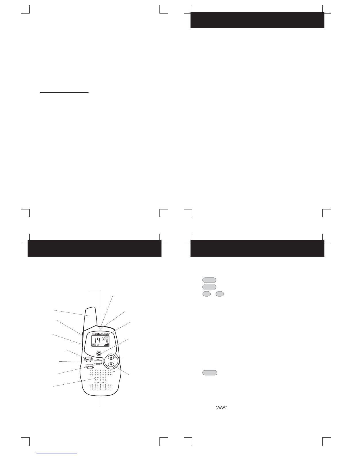
BellSouth 2252 User manual

2
Changing CHANNELS
MONITOR
MODE/LOCK
Battery
Sending Call Tones
.......................................................... 12
................................................... ...................... 12
............................. 12
............................................................. 15
Button (FUNCTION EDITING)
TRANSMIT POWER SELECTION Mode
CHANNEL SCAN
Charge Level/Low Battery Indication
To Charge the COMMUNICATOR
................................... 13
................................................................. 14
.............................. 14
............................................. 15
SPECIFICATIONS
CHANNEL TABLE
................................................................... 15
.................................................................... 16
....................................................................... 21
TROUBLESHOOTING
WARRANTY
LICENSING
.............................................................. 17
............................................................................ 18
.....
Removing the Belt Clip
Installing the Belt Clip
Connecting the Adapter
Accessory Connection
........................................................ 8
......................................................... 8
...................................................... 8
........................................................ 8
Battery Installation
LCD Screen
Turning the Unit ON
Turning the Unit OFF
Adjusting Speaker Volume
Receiving a Signal
Transmitting a Signal
............................................................. 9
.................................................................... 10
............................................................ 11
.......................................................... 11
.................................................... 11
........................................................... 11
.......................................................... 11
OPERATION
SPECIAL FEATURES
CARE AND SAFETY
FCC NOTICE
................................................... 3
..................................................... 5
............................................................... 7
GETTING STARTED
Contents
4
Special FeaturesSpecial Features
1
BELT CLIP
MONITOR button - Press to tune in and hold onto weak signals.
UP / DN (DOWN) buttons - Used for changing channels,
codes, and setting the receive volume.
TALK (PUSH TO TALK) button - Used for making a call.
CALL button - Press to transmit a CALL Tones.
MIC - Microphone
ANTENNA
LCD (Liquid Crystal Display) Screen - Displays current channel
selection and other radio status symbols.
BATTERY COMPARTMENT COVER LATCH (Located on the
rear) - Secures BATTERY COMPARTMENT cover.
EAR/MIC jack - This jack is used to connect a 3.5 mm stereo
headset/mic.
POWER ON/OFF button POWER- Press and hold the button
to turn the unit ON or OFF.
MODE /LOCK button - Press to shift into FUNCTION editing
mode. Press and hold for 5 seconds to lock the buttons.
SPEAKER
BATTERY COMPARTMENT - Houses
four(4) alkaline or Ni-MH rechargeable batteries (not
(Located on the rear)
included with the package).
SCAN button - Used to activate and deactivate channel
scanning.
TX LED indicator - Illuminates red when transmitting.
CALL
BELT CLIP(LOCATED
ON THE REAR)
(Pg. 8)
EAR/MIC/CHARGER
JACK (Pgs. 8, 14)
ANTENNA
(Pgs. 5-7)
UP BUTTON
(VOLUME/CHANNEL)
(Pgs. 4, 11-14, 17)
DOWN BUTTON
(VOLUME/CHANNEL)
(Pgs. 4, 11-14, 17)
BATTERY COMPARTMENT
(LOCATED INSIDE)
(Pgs. 4, 6, 9)
TX LED INDICATOR
(Pg. 4, 11, 14)
CALL BUTTON
(Pg. 4, 12, 14)
SCAN BUTTON
(Pg. 4, 13, 14)
SPEAKER
(Pg. 11)
LCD SCREEN
(Pgs. 4, 10-14, 17)
PTT BUTTON
(PUSH TO TALK)
(Pgs.4, 7, 11-14)
2252
MODE BUTTON
(Pgs. 4, 10, 12, 13, 17)
POWER ON/OFF
BUTTON
(Pgs. 4, 9, 11, 14)
MONITOR
BUTTON
(Pgs. 4, 11, 12, 17)
Congratulations on your selection of a quality
. With proper care and adherence to the set-up and
user instructions in this Owner's Manual, this unit will provide
BellSouth
Product
The COMMUNICATOR is a lightweight, compact two-way communication
device that can be used to communicate with family or friends at parks,
shopping malls, sporting events, concerts - any indoor or outdoor activity!
around buildings or large structures.
NOTE: The maximum transmission range will vary depending on terrain and
environment. Range will be greater in open fields, while range is shorter within and
Please read this Owner's Manual carefully to get the most out of your TWO-
This unit may not ensure privacy of communication.
WAY COMMUNICATOR.
Other features include ON/OFF VOLUME CONTROL and BATTERY SAVE
CIRCUITRY.
The COMMUNICATOR is compatible with other brands utilizing the same
The COMMUNICATOR has 14-CHANNELS, featuring a multi-functional
LCD Screen (which displays the current channel and various status icons).
frequency band (operating in the frequency range from 462.5625MHz to
467.7125MHz).
The COMMUNICATOR is the newest generation in personal two-way
communications. The COMMUNICATOR operates in a license-free radio
band (no FCC license is needed for its operation), on any of the 14 license-
free channels.
BellSouth is committed to providing quality products that fit
your needs. We would like to have any comments or
suggestions you might have on this product. You may mail
U.S. Electronics
105 Madison Avenue
New York, NY 10016
your comments to:
you with years of trouble-free service.
PRODUCT DESCRIPTION
VX
SC

Figure 1 Figure 2
Getting Started
8
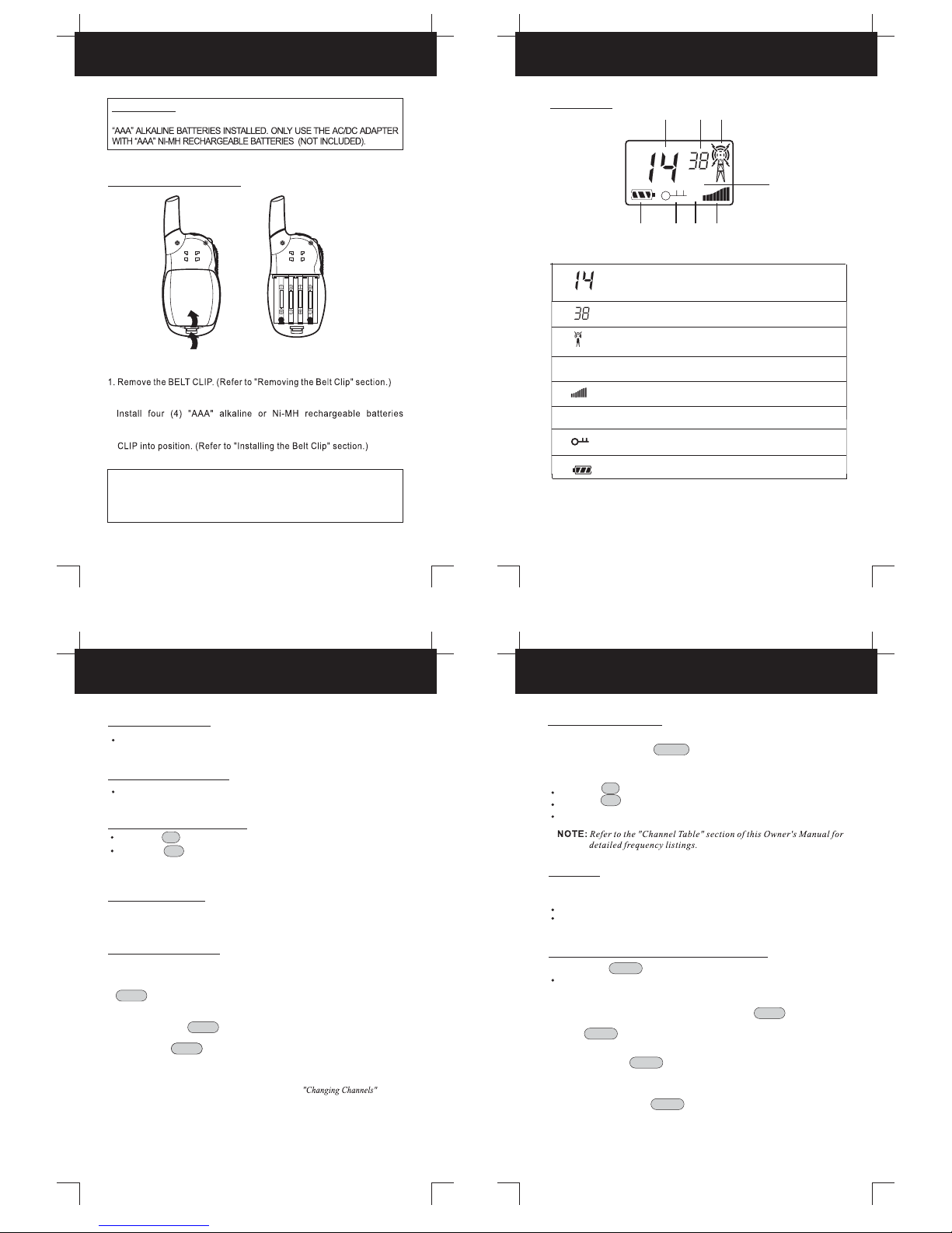
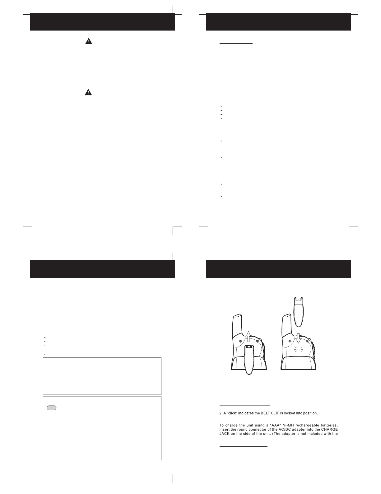
Removing the BELT CLIP
Installing the BELT CLIP
Connecting the Adapter
1. Pull the BELT CLIP LATCH away from the unit.
2. While pulling the BELT CLIP LATCH, push up on the BELT CLIP to
remove it from the unit, as shown in Figure 1.
1. Slide the BELT CLIP into the BELT CLIP SLOT as shown in Figure 2.
package.)
Care and SafetyCare and Safety
6
5
FCC Notice
7
The FCC requires that you be advised of certain requirements involving the
use of this device. This equipment has been tested and found to comply with
the limits for a Class B digital device, pursuant to Part 15 of the FCC Rules.
These limits are designed to provide reasonable protection against harmful
interference in residential installation. This device uses and can generate
radio frequency energy. If not installed and used in accordance with the
instructions, it may cause harmful interference to radio communications.
However, there is no guarantee that the interference will not occur in a
particular installation. If this equipment does cause harmful interference to
radio or television reception (which can be determined by turning the
equipment off and on), the user is encouraged to correct the interference by
one or more of the following measures:
Reorient or relocate the receiving antenna.
Increase the separation between the equipment and receiver.
Connect the equipment to an outlet on a circuit different from that to which
the receiver is connected.
Consult the dealer or an experienced radio/TV technician for help.
This equipment generates or uses radio frequency energy.
Changes or modifications not expressly approved in writing may cause
harmful interference and void the user's authority to operate this equipment.
FCC WARNING:
FCC INFORMATION: This device complies with Part 15 of the FCC Rules.
Operation is subject to the following two conditions:(1) This device may not
cause harmful interference, and (2) this device must accept any interference
received, including interference that may cause undesired operation. Privacy
of communications may not be ensured when using this equipment.
Your wireless hand-held portable transceiver contains a low power transmitter. When the
TALK button is pushed it sends out radio frequency (RF) signals. The devise is
authorized to operate at a duty factor not to exceed 50%. In August 1996, the Federal
Communications Commissions (FCC) adopted RF exposure guidelines with safety levels
for hand-held wireless devices.
Use only the supplied . Unauthorized ANTENNAS, modifications, or
attachments could damage the transmitter and may violate FCC regulations.
ANTENNA
To maintain compliance with the FCC's RF exposure guidelines
hold the transmitter and ANTENNA at least 2 inch (5 cm) from your face and
speak in a normal voice, with the pointed up and away from the face. If
you wear the handset on your body while using the headset accessory, use
only the supplied BELT CLIP for this product and when transmitting, take it out
of the belt to ensure that the is at least 2 inch (5 cm) from your body.
CAUTION:
ANTENNA
ANTENNA
SAFETY INFORMATION:
NOTE: Areas with potentially explosive atmospheres are often, but not always,
clearly marked. They include fueling areas such as below deck on boats; fuel or
chemical transfer or storage facilities; areas where the air contains chemicals or
particles, such as grain, dust, or metal powders; and any other area where you
would normally be advised to turn off your vehicle engine.
CAUTION
WARNING
Damaged ANTENNA
For Vehicles with an Air Bag
Potentially Explosive Atmospheres
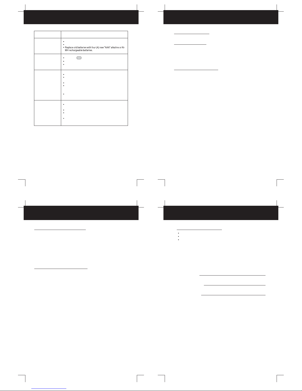
Batteries
Batteries
Blasting Caps and Areas
Do not use any COMMUNICATOR that has a damaged ANTENNA. If a
damaged ANTENNA comes in contact with the skin, a minor burn may result.
Turn your COMMUNICATOR OFF when in any area with a potentially
explosive atmosphere, unless it is a type especially qualified for such use (for
example, Factory Mutual Approved). Sparks in such areas could cause an
explosion or fire resulting in bodily injury or even death.
Do not place your COMMUNICATOR in the area over an air bag or in the air
bag deployment area. Air bags inflate with great force. If a
COMMUNICATOR is placed in the air bag deployment area and the air bag
inflates, the COMMUNICATOR may be propelled with great force and
cause serious injury to the occupants of the vehicle.
All batteries can cause property damage and/or bodily injury such as burns if
conductive material such as jewelry, keys, or beaded chains touches exposed
terminals. The material may complete an electrical circuit (short circuit) and
become quite hot. Exercise care in handling any charged battery, particularly
when placing it inside a pocket, purse, or other container with metal objects.
To avoid possible interference with blasting operations, turn your
COMMUNICATOR OFF near electrical blasting caps or in a "blasting area"
or in areas posted: "Turn off two-way radio". Obey all signs and instructions.
Do not replace or charge batteries in a potentially explosive atmosphere.
Contact sparking may occur while installing or removing batteries and cause
an explosion.
Care and Safety
To clean the unit, wipe with a soft cloth dampened with water. Don't use
cleaners or solvents on the unit; they can harm the case and leak inside,
causing permanent damage. Battery contacts may be wiped with a dry, lint-
free cloth.
Exposure to Radio Frequency Energy
The Relevant Guidelines and Standards Are:
For Portable Two-Way COMMUNICATORS
Electromagnetic Interference/Compatibility
The design of your COMMUNICATOR, which generates radio frequency (RF)
electromagnetic energy (EME), complies with the following national and
international standards and guidelines.
To ensure optimal unit performance and to ensure that exposure to RF
energy is within the guidelines in the above standards, the following
operating procedures should be observed:
Nearly every electronic device is susceptible to electromagnetic interference
(EMI) if inadequately shielded, designed, or otherwise configured for
electromagnetic compatibility.
Turn your unit OFF in any facilities where posted notices instruct you to do
so. Hospitals or health care facilities may be using equipment that is
Turn your unit OFF when on board an aircraft when instructed to do so. Any
use of the unit must be in accordance with airline regulations or crew
instructions.
sensitive to external RF energy.
If the unit gets wet, turn it OFF and remove the batteries immediately. Dry
the BATTERY COMPARTMENT with a soft cloth to minimize potential water
damage. Leave cover off the BATTERY COMPARTMENT overnight or until
completely dry. Do not use the unit until completely dry.
When transmitting with a COMMUNICATOR, hold the COMMUNICATOR
in a vertical position with its MICROPHONE 1 to 2 inches (2.5 to 5.0 cm)
away from your mouth. Keep the ANTENNA at least 1 inch (2.5 cm) from your
head and body.
If you wear a COMMUNICATOR on your body, ensure that the ANTENNA
is at least one inch (2.5 cm) from your body when transmitting.
FCC Report and Order FCC 96-326 (August, 1996)
American National Standards Institute (C95-1-1992)
National Council Radiation Protection and Measurements (NCRP-1986)
International Commission on Non-Ionizing Radiation Protection (ICNRP-1986)
Carefully remove your COMMUNICATOR from the Blister Pack. If there
is any visible damage, do not attempt to operate this COMMUNICATOR.
Return it to the place of purchase.
Accessory Connection
The COMMUNICATOR is designed to be used with accessories
(Earphone, Microphone, etc.).

10
9
LCD Screen
BATTERY INSTALLATION
Figure 3 Figure 4
Getting Started Getting Started
Getting Started Operation
11 1212
Changing CHANNELS
WARNING
DO NOT CHARGE THIS UNIT USING AN AC/DC ADAPTER WITH REGULAR
Adjusting Speaker Volume
Transmitting a Signal
While holding the button, speak into the unit using a normal tone
of voice.
TALK
Release the button when you have finished transmitting.TALK
Check the channel activity by pressing and holding the
button. You'll hear static if the channel is unoccupied. Don't
TRANSMIT if someone is talking on the channel. Press and hold the
button to TRANSMIT. The TX icon is displayed. Hold the unit
in a vertical position with the MICROPHONE 2 to 3 inches (5 to 7.5)
MONITOR
TALK
from the mouth.
1.
2.
3.
Changing CHANNELS
The COMMUNICATOR has 14 available channels. To change channels:
Press the button to move to a higher channel.
Press the button to move to a lower channel.
The channel changes from 1 to 14, or from 14 to 1.
UP
DN
MONITOR
Press the button for normal monitoring.MONITOR
You can use the button feature to check for weaker signals in the current
channel.
MONITOR
1.
2.
MENU/LOCK Button (FUNCTION EDITING)
Press and hold the MODE button for 5 seconds to activate or deactivate the
BUTTON LOCK mode. The BUTTON LOCK icon is displayed on the LCD Screen.
Depress the MODE button momentarily;
Press the button briefly to enter into the FUNCTION EDIT modes in due
order: mode.HI/LOW
NOTE: In the current FUNCTION EDIT mode, press the button to return
to the NORMAL mode after making your selection. In the FUNCTION EDIT mode,
press the MODE button again to shift from the current option in each submenu
TALK
to the next option.
NOTE: Channel Change Operations are disabled during BUTTON LOCK
mode. Press and hold the MODE button again to deactivate BUTTON LOCK
mode.
AAA
AAA
AAA
AAA
Receiving a Signal
The unit is continuously in the RECEIVE mode when the unit is ON
and not transmitting. When you receive a signal on the current
channel, the RX icon is displayed. (See “LCD Screen” for details.)
Press the button to increase the volume.UP
Press the button to decrease the volume.DN
The speaker volume level is indicated by the number of bars displayed
in the upper right corner of the LCD.
Press and hold the button until it “beeps” for continuous
monitoring.
MONITOR
Turning the Unit ON
Turning the Unit On/Off
Press and hold the button. The unit will “beep” and the LCD
Screen will turn blank.
POWER
Press and hold the button. The unit will “beep” and thePOWER LCD
Screen will display then the current channel.2r5
The COMMUNICATOR has a built in POWER SAVER feature for maximum
battery life. But when the is not being used, conserve
battery power by pressing the button to OFF. Remove the batteries ifPOWER
COMMUNICATOR
be used for a long period of time.the unit will not
Press and release the MODE button, the current channel number
flashes on the LCD Screen.
While the channel number is flashing:
1.
2.
4. Reinstall the BATTERY COMPARTMENT COVER and return the BELT
2. Remove the BATTERY COMPARTMENT COVER from the BATTERY
COMPARTMENT. See Figure 3.
(batteries not included) following the polarities as shown in Figure 4.
3.
NOTE: In order for other people to receive your transmission, they must also be on
the same channel you are currently using. Refer to the section
for more information.
D
AB
C
F.
SC- Displayed during the CHANNEL SCAN mode.
D. VX - Displays during the TALK mode.
H.
-
Displays the current BATTERY LEVEL charge.
G. - D
isplays when the LOCK mode is activated .
A. - CHANNEL NUMBER. Changes from 1 to 14 as selected14
By user.
E.
- Displays the current volume level.
B. - CTCSS code. Changes from 1 to 38 as selected by user.
C.
- TX icon. Displayed when transmitting signal..
EF
G
H
VX
SC

13
Operation
VOX Selection
1. Press the MODE button twice, the VX icon will flash on the LCD
Screen.
2. Press the button to turn the VOX feature ON, or press theUP DN
button to turn the VOX feature OFF.
3. In the VOX mode, the VX icon will be displayed.
4. To confirm your selection and return to the NORMAL mode, press
the button.TALK
5. To confirm and shift to the next option, press the MODE button.
The FRS is capable of voice activated (VOX) transmission. In VOX
mode, the radio will transmit a signal only when it is activated by your
voice or other sound around you. VOX operation is not recommended if
you plan to use your radio in a noisy or windy environment.
NOTE: To save power, the unit will not turn ON the LCD Screen light when in
the VOX mode.
15
Operation
14
Operation
Channel Table
16
14 Channels
FRS (0.5W)
About 2 Miles
Channels Available
Output Power (TX)
Range
Sending Call Tones
Specifications
You can use Call Tones to alert the other user to identify yourself. You can
also use Call Tones to signal the beginning or the end of a transmission.
1. Press and release the button.CALL
2. Your Call Tones will transmit to nearby receivers set to the same
channel.
NOTE: The COMMUNICATOR allows you to communicate with standard FRS
models by using channels 1 through 14.
CHANNEL SCAN
CHANNEL SCAN performs searches for active signals in an endless
loop from 1 to 14.
Press and release the button to activate CHANNEL SCAN. The.
channel number on the LCD
SCAN
Screen changes rapidly until an active signal
is detected.
2. When an active signal (one of 14 channels) is detected, CHANNEL SCAN
pauses keeping the active signal broadcasted.
3. Press the button to communicate through the active signal channel
and CHANNEL SCAN is deactivated.
TALK
5. Press the MODE button to deactivate CHANNEL SCAN mode.
4. When an active signal (one of 14 channels) is detected, but another
channel is desired, press the or button to bypass the currentUP DN
the current channel and continue to search for another active channel.
1.
Battery Charge Level/Low Battery Indication
The BATTERY CHARGE LEVEL is indicated by the number of squares
present inside the BATTERY icon on the LCD Screen.
When the BATTERY CHARGE LEVEL is low, the BATTERY icon will
flash to indicate that the batteries need to be replaced.
To use this FRS with an AC/DC ADAPTER (not included) and
rechargeable BATTERY PACK (not included) do the following:
To Charge the FRS
Plug the 7.5 V DC / 200 mA ADAPTER (not included) into the EAR/
MIC/CHARGER JACK on the top of the COMMUNICATOR and turn it
on by pressing the button.POWER
NOTE: The COMMUNICATOR cannot transmit calls while the BATTERY PACK
is being charged. It takes approximately 4 to 5 hours to fully charge the batteries
if they are at their lowest level.
CHANNEL NUMBER
FREQUENCY(MHz)
1
2
3
4
5
6
7
8
9
10
11
12
13
14
462.5625
462.5875
462.6125
462.6375
462.6625
462.6875
462.7125
467.5625
467.5875
467.6125
467.6375
467.6625
467.6875
467.7125
CHANNEL TABLE
NOTE: The maximum transmission range will vary depending on terrain and
environment.

19
Warranty
18
Warranty
SYMPTOM SOLUTION
No power.
The may be weak.batteries
Check batteries. Ensure that the batteries are installed properly.
Reception
is weak. The receiving signal may be weak and/or out of range.
If this happens press the button.MONITOR
Range is
limited.
Wearing the radio close to the body, such as in a pocket or on
a belt, will decrease range; change the location of the radio.
may limit the range significantly.
Open fields provide the maximum range, while steel/concrete
structures, heavy foliage, and use in buildings and in vehicles
The maximum range will vary depending on terrain and environment.
Replace with new if the BATTERY CHARGE LEVEL
indicator is low.
batteries
Batteries may be weak.
Sound distortion
problems.
Radios too far apart. Obstacles interfere with transmission.
Talk range is from 2 miles in clear unobstructed conditions.
Radios too close. Radios must be at least 5 feet apart; increase
your distance.
If you are transmitting, speak in a normal tone of voice, 2 to 3
inches away from the MICROPHONE.
If you are receiving, lower the VOLUME to a comfortable level.
Warranty
20
address of the authorized service center is:
During the first thirty (30) days, a defective product is eligible for over-the-counter
exchange at the retailer from whom it was purchased. After thirty (30) days, the
defective product should be returned to the authorized service center. The shipping
What To Do for Warranty Service
Your unit will be repaired or replaced if examination by the service center
determines the unit is defective.
An unit received damaged as a result of shipping will
to file a claim with the carrier to cover repair costs.
COMMUNICATOR
require you
An unit received with missing parts or with damage due
to abuse, inadequate packing, or some other noncompliance with this limited
COMMUNICATOR
Troubleshooting
17
warranty will be returned to you C.O.D., freight collect.
Warranty Service Provided
Warranty Information
This warranty gives you specific legal rights and you may have other rights which
vary from state to state. Some states do not allow the exclusion or limitations of
special, incidental or consequential damages or limitations on how long a warranty
lasts, so the above exclusion or limitation may not apply to you.
disclaims any implied warranty, including the warranty of
merchantability and the warranty of fitness for a particular purpose, as of the date
of one year from your original purchase of the unit.
assumes no responsibility for any special, incidental, or consequential
BellSouth Products
BellSouth
Products
COMMUNICATOR
damages.
If you purchased the unit new from a retail vendor,
warrants the unit against defects in material and workmanship for a
period of one (1) year from the original date of purchase. This warranty is in lieu
of all other expressed warranties. This warranty begins when you purchase the
unit and continues for (1) one year unless you sell or rent the
BellSouth
Products
COMMUNICATOR
COMMUNICATOR
unit, in which case the warranty stops.
This limited warranty sets forth all responsibilities regarding
your COMMUNICATOR. There are no other expressed or implied warranties from
BellSouth Products
BellSouth Products.
BellSouth Products
One-Year Limited Warranty
This warranty does not cover damage resulting from accident, misuse, abuse,
improper installation or operation, lack of reasonable care, unauthorized
modification, or the affixing of any attachment not provided by
with the unit, and/or loss of parts. This warranty is voided in the
event any unauthorized person opens, alters, or repairs the unit. All
equipment being returned for repair must be suitably packaged.
does not warrant that this equipment is compatible with the type of accessory of any
BellSouth Products
BellSouth
BellSouth Products
COMMUNICATOR
particular communicator company or the services provided by it.
Warranty Service Not Provided
returned to you C.O.D., freight collect.repaired and will be
NOTE: An COMMUNICATOR unit received which was not made for
or which is not defective as determined by our test procedures will not be
BellSouth
Products
US Electronics CONSUMER CENTER
C/O Southern Bonded Warehouse
7137 Southlake Parkway
Morrow, GA 30260
To Obtain Warranty Service
Provide proof of the date of purchase within the package.
Prepay all shipping costs to the authorized service center.
Include a return shipping address within the package.
for the unit should you have to return it.COMMUNICATOR
Please retain your sales receipt, the carton, the packing materials, and
the printed material. The original carton is the best shipping container
For your reference:
Model Number
Date of Purchase
Name of Dealer
Press the button to increase VOLUME.UP
Customer Service Telephone Number:
1-800-864-2199
Visit Us on the Web:
www.uselectronics.info

COMMUNICATOR
MODEL 2252
OWNER'S MANUAL
INSTALLATION AND
OPERATING INSTRUCTIONS
Licensing
FOR INFORMATION, PLEASE SEEINSTALLATION
SEPARATE QUICK START GUIDE.
2002 BellSouth Corporation
Visit Us on the Web:
www.uselectronics.info
PLEASE READ THIS
OWNER'S MANUAL
CAREFULLY BEFORE
USE. KEEP FOR
YOUR REFERENCE.
Licensing
Make certain you receive the best
performance from your FRS.
Read this Owner's Manual first.
STOP
2252 Made in China
LD
Visit Us on the Web
www.uselectronics.info
21
NotesNotes
22
CALL
2252
VX
SC

Quick Start
Figure 1 Figure 2
Quick Start
Model 2252
See the Owner's Manual for full details.
WARNING
DO NOT CHARGE THIS UNIT USING AN AC/DC ADAPTER WITH REGULAR
BATTERY INSTALLATION
AAA
AAA
AAA
AAA
The COMMUNICATOR has a built in POWER SAVER feature for maximum
battery life. But when the is not being used, conserve
battery power by pressing the button to OFF. Remove the batteries ifPOWER
COMMUNICATOR
be used for a long period of time.the unit will not
4. Reinstall the BATTERY COMPARTMENT COVER and return the BELT
2. Remove the BATTERY COMPARTMENT COVER from the BATTERY
COMPARTMENT. See Figure 3.
(batteries not included) following the polarities as shown in Figure 4.
3.
AAA
AAA
AAA
AAA
Adjusting Speaker Volume
Transmitting a Signal
While holding the button, speak into the unit using a normal tone
of voice.
TALK
Release the button when you have finished transmitting.TALK
Check the channel activity by pressing and holding the
button. You'll hear static if the channel is unoccupied. Don't
TRANSMIT if someone is talking on the channel. Press and hold the
button to TRANSMIT. The icon is displayed. Hold the unit
in a vertical position with the MICROPHONE 2 to 3 inches (5 to 7.5)
MONITOR
TALK
from the mouth.
1.
2.
3.
Receiving a Signal
The unit is continuously in the RECEIVE mode when the unit is ON
and not transmitting. When you receive a signal on the current
channel, the icon is displayed. (See “LCD Screen” for details.)
Press the button to increase the volume.UP
Press the button to decrease the volume.DN
The speaker volume level is indicated by the number of bars displayed
in the upper right corner of the LCD.
Turning the Unit ON
Turning the Power On/Off
Press and hold the button. The unit will “beep” and the LCD
Screen will turn blank.
POWER
Press and hold the button. The unit will “beep” and thePOWER LCD
Screen will display then the current channel.2r5
NOTE: In order for other people to receive your transmission, they must also be on
the same channel you are currently using. Refer to the section
for more information.
Modelo 2252
FIGURA 1 FIGURA 2
3.
1.
1.
2.
3.
Presione y mantenga presionado el botón . Se oirá un sonida
"bip" y la PANTALLA LCD mostrará y el canal actual.
POWER
Presione y mantenga presionado el botón . Se oirá un sonida
"bip" y la PANTALLA LCD quedará en blanco.
POWER
presionado el botón para TRANSMITIR. EL INDICADORMONITOR
Mientras mantiene presionado el botón hacia la unidad con
un tono normal de voz.
TALK
.TALK
Table of contents
Other BellSouth Cell Phone manuals