Safety Instructions: If attachments, accessories, or conguration-modifying components that are
located in the load path affect operation of the lift, affect the lift electrical listing, or affect intended
vehicle accommodation are used on this lift and, if they are not certied for use on this lift, then the
certication of this lift shall become null and void. Contact the participant for information pertaining
to certied attachments, accessories, or conguration-modifying components.
BendPak lifts are supplied with concrete fasteners meeting the criteria as prescribed by ASTM E488/
E488M-18. Lift buyers are responsible for any special regional, structural, and/or seismic anchoring
requirements specied by any other agencies and/or codes such as the Uniform Building Code (UBC)
and/or International Building Code (IBC).
The manufacture, use, sale, or import of this product may be subject to one or more United States
patents, or pending applications, owned by BendPak Inc.
1645 Lemonwood Dr.
Santa Paula, CA USA
www.BendPak.com
LIFT TYPE: Surface Mount MANUFACTURER: BendPak. See data plate for product details
POWER: Electric/Hydraulic INSTALLATION: See manual or contact factory
Do Not Remove Engineered by BendPak Inc., USA Made in China
PN 5905940
(Yellow color in file represents what should be clear PET material and SHOULD NOT print as Yellow ink.)
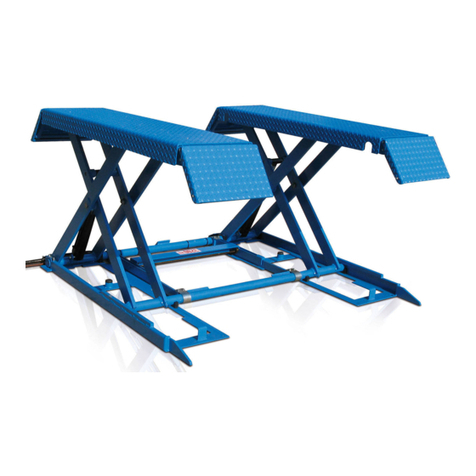
MD-6XP Product Decal Positioning
A
C D
B
MD-6XP_BendPak_Cylinder_Decal.pdf:
Material: Clear Adhesive PET
Size: 16”W x 3”H
Thickness: 4 Mil
Finish: Matte Overlaminate (No gloss)
Ink: U.V. protected, Opaque White
Print Process: Silk Screen, 85 line-screen (Yellow color in file represents what should be
clear PET material and SHOULD NOT print as Yellow ink. White area in file represents
Opaque White ink.)
Lamination: Clear laminate non-glare medium matte over-laminate (No gloss) for abrasion,
chemical and ultra violet protection.
Warning_Operation_Inst_Label_5905577.pdf:
Size: 3.5”W x 8.25”H
Material: 4 Mil. Permanent White Adhesive Vinyl
Thickness: 4 Mil
Ink: U.V. protected CMYK 2/C Process
Finish: Matte Overlaminate (No gloss)
Print Process: Offset Lithography - 200 line-screen or 300
p.p.i. for digital
Lamination: Clear laminate non-glare medium matte over-
laminate (No gloss) for abrasion, chemical and ultra violet
protection.
Warning_Drive_Car_Over_Label_5905576.pdf:
Size: 3.5”W x 11”H
Material: 4 Mil. Permanent White Adhesive Vinyl
Thickness: 4 Mil
Ink: U.V. protected CMYK 2/C Process
Finish: Matte Overlaminate (No gloss)
Print Process: Offset Lithography - 200 line-screen or 300 p.p.i. for digital
Lamination: Clear laminate non-glare medium matte over-laminate (No gloss) for abra-
sion, chemical and ultra violet protection.
Product_Data_Label_5905940-New.pdf:
Size: 4.5”W x 2.3”H
Material: 4 Mil. Permanent White Adhesive Vinyl
Thickness: 4 Mil
Ink: U.V. protected CMYK 2/C Process
Finish: Matte Overlaminate (No gloss)
Print Process: Offset Lithography - 200 line-screen or 300
p.p.i. for digital
Lamination: Clear laminate non-glare medium matte
over-laminate (No gloss) for abrasion, chemical and ultra
violet protection.
PN 5905577
PN 5905576
PN 5905940
PN 5905204
Clear PET material and
SHOULD NOT print as Yellow
TO PLACE ORDER
Visit www.bendpak.com
or dial 1-800-253-2363
Monday - Friday
6 a.m. - 4:30 p.m. PST
WARNING
!
WARNING
!
Maximum Lifting Capacity
6,000 lbs. / 2722 kg
FAILURE TO READ AND UNDERSTAND THE FOLLOWING WARNINGS MAY
RESULT IN PERSONAL INJURY AND/OR PROPERTY DAMAGE.
KEEP HANDS AND FEET AWAY FROM MOVING PARTS.
Read and understand entire contents of operation manual and
warnings below before operating this equipment.
Before raising a vehicle, make sure there is at least 1 inch of clearance
between the lift and the vehicle. The MD-6XP requires space between
the ground and your vehicle to build up enough force to raise vehicle.
It cannot raise a full load from a completely flat starting position.
WARNING
!
USE PROPER ADAPTERS
Do not attempt to lift trucks or other frame type vehicles with
standard rubber contact pads. NEVER use lift with missing
or damaged rubber contact pads. ALWAYS REPLACE rubber
contact pads when worn or damaged. Contact BendPak or your
BendPak dealer for product information.
3 Never exceed rated capacity of the lift.
3 Do not operate the lift if any component is defective or worn. If you
find a problem, remove the lift from service and get it repaired.
3 Never operate lift with any person or equipment below it.
3 Drive vehicle completely over lift; make sure vehicle is centered and
stable prior to raising or lowering.
3 Keep a visual line of sight to the lift during operation.
3 Stand clear of the lift during operation.
3 Only leave the lift on the ground or on a locking position.
3 Keep all body parts and other objects away from pinch points during
operation.
3 Only use lift on flat, defect-free concrete.
3 Always use the lift pads that came with your lift. If a lift pad is
missing or damaged, replace it.
3 Visually confirm lift is on locking position before working under or
near lift.
Required for use when lifting
trucks, vans or other frame
vehicles that require additional stability.
FRAME CRADLE
ADAPTERS
SKU# 5215506
PN 5905576
Read and understand all Danger, Warning, and Caution messages
and operation procedures before using lift. Keep hands and feet
away from moving parts. Do not work under or near a raised vehicle
unless the lift is on a locking position.
OPERATION INSTRUCTIONS
Before raising a vehicle, make sure the weight of the vehicle does
not exceed the rated capacity of the lift, that all persons and
obstacles are away from the lift, and that the lift is lowered.
To Raise Lift:
1. Drive vehicle over lift; there must be at least 1 inch of clearance
between vehicle and lift.
2. Raise the lift until the tires are off the ground.
3. Make sure the vehicle is balanced and the pads are in contact with the
vehicle’s lifting points.
4. Raise the lift to just past the desired height.
5. Lower the lift down onto the most recently passed locking position.
Lock Pin needs to firmly rest against Lock Block, as shown in Figure A.
Before lowering a vehicle, make sure the area around and under
the lift is clear of people and obstacles.
To Lower Lift:
1. Raise the lift up for a second or two. This moves the Release Cam into
position so that it can push the Lock Pin over the Lock Block, allowing
the lift to lower, as shown in Figure B.
2. Lower the lift to the ground.
3. Remove all pads, check under the vehicle for obstacles, then drive the
vehicle off the lift.
WARNING
!
LOCKED POSITION
Figure A
LOWERING POSITION
Figure B
WARNING
!
ALWAYS make sure the lift is firmly in a locked position before
working on a raised vehicle.
PN 5905577
Lock Block
Release Cam
Lock Bar
Lock Pin
Lock Block
Release Cam
Lock Bar
Lock Pin


