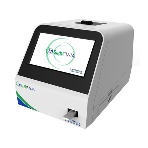
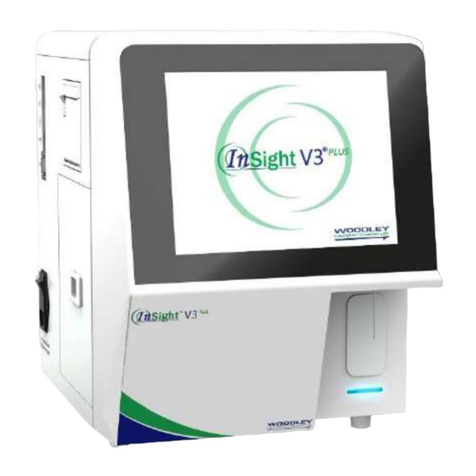
Woodley InSight V-IA PLUS User manual

Veterinary Immunoassay Analyser
User Manual


Contents
I Product Introduction...................................................................................................................... 4
I.1 Analyser Structure............................................................................................................... 4
I.2 Intended Use ....................................................................................................................... 4
I.3 Technical Specifications ...................................................................................................... 4
I.4 Analyser System.................................................................................................................. 5
I.5 Analyser Test Information.................................................................................................... 5
II Contents......................................................................................................................................... 7
III Installation....................................................................................................................................... 8
III.2 Instructions ........................................................................................................................ 8
III.3 Operation Procedures ....................................................................................................... 8
III.4 Warnings............................................................................................................................ 9
IV Software Introduction ................................................................................................................... 10
IV.1 Main Interface.................................................................................................................. 10
IV.2 Testing Interface ...............................................................................................................11
IV.3 Batch Test........................................................................................................................ 12
IV.4 Results Records Interface ............................................................................................... 13
IV.5 Item Interface................................................................................................................... 15
IV.6 Settings............................................................................................................................ 18
IV.7 Android Setting................................................................................................................ 24
V Quality Control............................................................................................................................. 27
VI Further Product Information ....................................................................................................... 29
VI.1 Security Classification of Medical Electrical Equipment ............................................... 29
VI.2 Contraindications........................................................................................................... 29
VI.3 Warnings, Precautions and Limitations......................................................................... 29
VII Maintenance and Care .............................................................................................................. 32
VII.1 Daily Maintenance and Care .............................................................................................. 32
VII.2 Troubleshooting – Common Faults and Solutions ............................................................. 32
VII.3 Error Codes ........................................................................................................................ 33
VIII Interpretation of Medical Device Label..................................................................................... 38
VIX Transportation Conditions........................................................................................................ 38
VIX.1 Transportation ................................................................................................................... 38

4
I Product Introduction
I.1 Analyser Structure
I.2 Intended Use
InSight V-IA Plus Veterinary Immunoassay Analyser uses immunofluorescence
technology to provide accurate, quantitative laboratory results.
For in vitro diagnostic use only.
For veterinary use only.
InSight V-IA Plus Veterinary Immunoassay Analyser is suitable for use in veterinary
laboratories.
I.3 Technical Specifications
I.3.1 Main parameters
◆Software Version: Version 1
◆LED or Diode laser
◆Outputs: 1. USB interface (2)
2. Ethernet interface (1)
3. Serial port: Automatic LIS uploading & PC adjustment
◆Display: 24-bit true colour LCD screen
◆Sample Type: Whole blood, serum and plasma
◆Power Supply: Host Input DC: 12V 5A
Adaptor Input: 100-240VAC; 50/60Hz
◆Standard curve
Storage Method: ID card with 4K memory
◆Dimensions: 213 (W) x 243 (D) x 195 (H) mm
◆Weight: 4kg
◆Operating Temperature: 10-30°C
◆Relative Humidity: ≤70%

5
I.3.2 Performance Specifications
◆Repeatability: CV≤10%
◆Stability: σ≤±8%
◆Linear Correlation: r≥0.97
◆Accuracy: Δn≤±15%
I.4 Analyser System
◆Hardware Core: ARM Cortex™
◆Software: Android 5.1
◆Memory: 8G
◆Data Capacity: 10,000 sets of patient and quality control data
I.5 Analyser Test Information
1.5.1 Cartridges
Only use genuine InSight V-IA cartridges provided by Woodley Equipment Company.
◆There is a barcode on the cartridge. It shows the Lot Number of the cartridge. InSight
V-IA Plus will read the barcode to recognise which items and which Lot is being tested.
◆The Lot Number and the name will show on the information of the barcode.
Lot Number Name Rule:
Long Lot Number: H0ABYYMMXX
Short Lot Number: ABXX
Code
Meaning
Sample: H053210113
Sample Meaning
H0
Fluorescent products
H0
Fluorescent products
AB
Test name
32
T4
YYMM
Manufacture date
2101
Produce in January,2021
XX
Lot
13
Number of Lot
ABXX
Barcode No.
3213
Short Lot number
◆The arrow indicates the direction the cartridge is inserted into the analyser.
◆The sampling port is where the sample is added. Please follow the instructions
provided with the test.

6
◆The detection window is the area the analyser will read the fluorescent signal.
◆C Line:
This cannot be seen by the user. It is a fluorescent control line which the analyser will
use to check the result of the cartridge.
◆T Line:
This cannot be seen by the user. It is a fluorescent test line. The analyser will read the
fluorescent signal and ID chip information to give the result.
◆Blue Line:
This can be seen at the end of the detection window. When the sample has been
added to the cartridge correctly, the blue line will disappear after the sample has
flowed over the detection window. If the blue line is still visible after the incubation
time, the analyser will show ‘Test invalid’ after the test has been completed.
Caution: If the blue line is still obviously visible after analysis, please check if the test
has been completed correctly.
◆Insert the Test Kit:
Notice: Please insert the test kit to the end of cartridge holder.
Correct Incorrect, the finger is obstructing
the cartridge holder

7
1.5.2 ID chip
All the parameters and information of the cartridge is saved in the ID chip. Each Lot
Number of tests has a unique ID chip.
You can read the ID chip information on the Item page.
1.5.3 Test principle
1. Sample is added to cartridge and migrates to the fluorescent antibody that is labelled
on the cartridge.
2. Laser light source excites fluorescence.
3. The emitted light is collected and converted into electrical signals.
4. The concentration is calculated from the signal and ID chip parameter.
II Contents
No.
Accessories
Quantity
Remark
1
Power Adaptor
1
Included
2
Instructions for Use
1
Included
3
Ethernet Cable
1
Included

8
III Installation
III.1 Installation
III.1.1 Unpacking and checking
1. Gently remove the analyser and accessories from the packaging box. Save the
packaging materials for future transport or storage of the analyser. Check the
accessories against the packing list.
2. Check the analyser and accessories to see if they are in good condition.
Notice: If there are any problems, please contact Woodley Equipment Company.
III.1.2 Analyser placement
1) The analyser should be placed in a clean and ventilated room with temperature
between 10°C ~ 30°C, relative humidity of less than 70%, away from direct sunlight.
2) Make sure the vents are not obstructed and that there is at least 5cm of clearance
around the analyser.
3) Connect the power adapter to the power interface of the analyser and turn on the
power.
4) Do not place any items on top of the analyser.
III.2 Instructions
Please note that the operating temperature of test reagents is based on each test kit’s
instructions. Perform tests in strict accordance with the cartridge operating instructions
provided in each test kit.
III.3 Operation Procedures
III.3.1 Preparation
1) When switched on, the analyser will run a self-test and the cartridge holder retracts
as shown below.
2) The software will start automatically and display the main home screen.
3) For the use and storage of reagents, please refer to the cartridge operating
instructions.
4) Insert ID code chip for the test to be analysed. Select “Read ID Card”.
5) Enter patient details in the ‘detail’ section.
Cartridge Holder
Cartridge

9
6) Select standard test or instant test (refer to Section IV.2).
7) Place the test cartridge with sample (follow cartridge operating instructions) into the
cartridge holder and run prepared test.
Notice:
⚫Do not touch the cartridge holder when it’s moving.
⚫Do not interfere with the software during testing.
III.3.2 After analysis
1) The test cartridge will be released from the analyser once the test is complete.
2) The cartridge holder will reset.
3) Used test cartridges and pipette tips should be disposed as medical waste in
accordance with local regulations.
III.4 Warnings
The sign denotes notifications and errors.

10
IV Software Introduction
IV.1 Main Interface
Figure 4.1
As shown in Figure 4.1, there is a home [Menu] key at the bottom of all screens. Click the
[Menu] key and the screen in Figure 4.1 will display. From left to right, the screen will
display [Test], [Batch Test], [History], [Item], [QC] and [Settings]. Select an icon to enter
into the corresponding screen.

11
IV.2 Testing Interface
Figure 4.2.1
1. Click [Test] option on the main home screen and Figure 4.2.1 will display. (Test
interface will be change in Bi-directional mode (see chart 6.2.5 below).
2. Insert ID chip in the ID Port on the side of the analyser and select “Read ID Card”
before using a new lot of test cartridges.
3. After the ID chip is recognised, select sample type and manually input sample
number if required.
4. Select [Detail] to input more detailed patient information (patient name, age etc).
5. Select [Standard Test] or [Instant Test] after inputting patient information. Standard
Test means the analyser will countdown the reaction time, then analyse the
cartridge and report results. This option is recommended for routine testing. Instant
Test means the user needs to use a timer to countdown the reaction time before
putting the cartridge in the analyser. Once the timer has completed, the user inserts
the cartridge into the analyser to analyse the cartridge and report results. This
option is recommended for multiple sample batch testing.
Caution: Wrong test mode will cause incorrect test result.
6. Prepare sample according to each test kit insert. Then apply sample to the test
cartridge. If Standard Test selected, insert the test cartridge into the cartridge port. If
Instant Test selected, start the timer and leave the cartridge on the bench.
7. When patient information has been inputted, the user can select [Test] option to
start the analysis.
8. After each test, the result will be displayed on the screen and will automatically print
on the internal thermal printer.

12
IV.3 Batch Test
Figure 4.3.1
1. The screen for batch testing is shown in Figure 4.3.1. The user can select the
sample type and test item and add or delete the item to be tested.
2. Select the test item to determine the time that is displayed in the interface [Time].
3. Select [Sample +1] to add another sample. Select the corresponding sample and
select [Delete] to delete a sample. (Figure 4.3.2)
Figure 4.3.2
4. After the sample is added, a sample No. will be automatically assigned. The user
has the option to customise the code, select the sample and select the [Sample
Number] to edit the code.

13
5. Select [Start], the analyser will start to count down. Simultaneously, the next sample
will count down. The analyser will prompt the user to insert the correct test kit when
the countdown is complete.
IV.4 Results Records Interface
1. In the [History] screen, users can view previous test results.
2. After each test has completed, the system will automatically save the results to the
analyser memory.
3. Adjust the dates to search for a sample. Select [OK].
Figure 4.4.1
4. Select [Upload] in Figure 4.4.1 to upload the selected records or all records to the
LIS/HIS.
5. Select [Print] in Figure 4.4.1 to print the selected records or all records on the
internal printer.
6. Select [Export] in Figure 4.4.1 to export the selected records or all records to a
USB.
7. Select [Delete] in Figure 4.4.1 to delete the selected records or all records.
8. Select [Advanced] in Figure 4.4.1 to check the advanced information. You can input
or modify the patient information on the Advanced page as shown in Figure 4.4.2.
9. Select [History Search] in Figure 4.4.1, set the search date range and press confirm
to search the results as shown in Figure 4.4.3
10. Select [Classified Statistics] in Figure 4.4.4. After selecting a date range, press
confirm to view the statistics of how many tests have run within the selected time
frame.

14
Figure 4.4.2.
Figure 4.4.3
Figure 4.4.4
Figure 4.4.4

15
IV.5 Item Interface
Figure 4.5.1
1. As shown in Figure 4.5.1, saved test lists can be viewed and reference ranges can
be set in the [Item] screen.
2. The user can edit reference ranges as shown in Figure 4.5.2.
Figure 4.5.2
3. Import ID Chip Information:
If the ID chip of the test item is lost, you can import the item information of the ID
chip using the method below.
◆Read ID chip from USB device
Provide the Lot No. of the test item and contact Woodley Equipment Company to
get the ID chip Hex file.

16
Set a folder name of “Hex” in the USB device root directory. Transfer the Hex file,
provided by Woodley Equipment Company, of the test item into the “Hex” folder as
shown in Figure 4.5.3.
Figure 4.5.3
Press [Read Hex] in the Item setting page.
Select the Hex file and press confirm as shown in Figure 4.5.4.
Item information will be saved on the ‘Save item’window.
Figure 4.5.4
◆Download ID chip from Cloud
Note: The analyser must be connected to the Wi-Fi before downloading the ID
chip. Please see Section IV Software Introduction for instructions on how to connect
to the Internet.
◆Download ID chip before test
Click ‘Download ID chip’on the Item setting page. Input the Lot No. of the test kit (4
digit number). Click confirm to download as shown in Figure 4.5.5.

17
Figure 4.5.5
◆Download ID chip while testing (analyser must be connected to Wi-Fi)
If the ID chip has never been read before, when the test kit is inserted into the
analyser to test, the analyser will show ‘Barcode doesn’t match any items in
analyser’.
Press ‘Download ID chip’and it will show the barcode number of the test kit.
Click confirm to download and new item information will save on the right window as
shown in Figure 4.5.6.
Select the item and press ‘Set as current’and test. Alternatively, press cancel and
retest again. The new items that have just been downloaded will match the test kit.
Figure 4.5.6
4. ID chip parameter
Click ‘Main item parameter’to enter the ID chip parameter page. You can check
detailed information about the current Lot of ID chip. See Figure 4.5.7.

18
Figure 4.5.7
IV.6 Settings
In the [Setting] screen, Institution Information, Test Setting, LIS Setting, System Setting
and Software Version can be viewed.
4.6.1 About and Institution
4.6.1.1 About Analyser
The analyser model and name will show on About page as shown in Figure 4.6.1.
The software version information is also shown on the About page. Users can upgrade
the software online after connecting to the Wi-Fi. Users can also transfer software onto
a USB device and then insert it into the USB port of the analyser. The software will
automatically update after detecting the USB.
Version:
Version + Release Version Number + Version Build
Caution:
⚫Do not change the upgrade document name or change the file.
⚫Please ensure that the power is on during the upgrade before restart.
⚫The analyser supports FAT32 format USB device. It does not support NTFS format.
⚫Other settings like reference of reagent items will be reset to the original settings.
⚫Do not uninstall the software apk, the analyser will be reset by uninstalling the
software.

19
4.6.1.2 Institution Information will be shown on the title of print paper.
Figure 4.6.1
There are two methods of changing institution information:
◆Change the institution directly:
1. Press the ‘Institution’ space.
2. Input the Institution name, press ‘Done’and it will be saved automatically.
◆ Change the institution by Register
1. Press the [Register] button to enter the register page.
Figure 4.6.1.1
2. Input the institution. The following shows an example of registering the institution
‘Woodley Equipment Company Ltd’. The registration code will be created by the
analyser and shown in the ‘Registration code’ space.

20
3. If analyser does not show the registration code, please contact Woodley Equipment
Company. Provide the following information, [Serial number] and [Institution] on the
register page (see the sample of Figure 4.6.1.3).
Caution: Please provide the correct word, include uppercase and lowercase letters.
The serial number on the register page consists of 8 characters. Do not use the SN
(serial number) on the back label of analyser.
4. Key in the [registration code] from Woodley after providing the information of [Serial
number] and [institution]. Please note the case of the letters (see Figure 4.6.1.4).
5. Restart the analyser to make the change.
Figure 4.6.1.2
4.6.1.3 Software update
◆Upgrade the software by USB device
Figure 4.6.1.3
Table of contents
Other Woodley Measuring Instrument manuals

Woodley
Woodley Insight User manual

Woodley
Woodley InSight Mini Chem User manual

Woodley
Woodley InSight V-CHEM User manual

Woodley
Woodley InSight V5 User manual

Woodley
Woodley InSight V3 PLUS User manual

Woodley
Woodley Skyla VB1 User manual

Woodley
Woodley Insight User manual

Woodley
Woodley InSight V-IA User manual

Woodley
Woodley The Edge User manual
Popular Measuring Instrument manuals by other brands

Everfine
Everfine PF9800 SERIES user manual

QUNDIS
QUNDIS Q heat W 4 Series Instruction manual and general information

Kobold
Kobold DUK operating instructions

Spirax Sarco
Spirax Sarco Colima Visco Installation and maintenance instructions

Retrotec
Retrotec DM-2 quick start guide

VR Avionics
VR Avionics TM1 Operational and installation manual