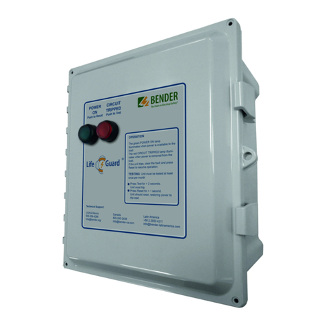
Bender GFGC-30 Technical specifications

GFGC_D00395_00_D_XXEN/05.2019
GFGC Protection Panel
Universal Ground Fault and Ground Continuity Panel
For 120 VAC to 600 VAC Grounded Systems
BENDER Group

2 GFGC_D00395_00_D_XXEN/05.2019
Ground Fault and Ground Continuity
Protection Panel GFGC
Protection Panel GFGC
Device features
• Universal voltage selection between 120
and 600 V
• Features ground fault detection, ground
integrity monitoring, and power inter-
ruption in case of alarm
• Predefined settings from factory
• 6 mA ground fault trip level
• Inverse time curve for interrupting cir-
cuit on a ground fault
• Adjustable ground continuity trip level
between 0.1 Ω…100 Ω (preset to 3 Ω)
• NEMA 12 painted steel enclosure
• External test and reset buttons
• External LED indication for power and
ground fault/ground integrity alarms
• Internal real-time indications of ground
fault current and ground integrity via
digital displays
Product description
The GFGC series of panels is an all-in-one solution for ground fault detection, ground
continuity monitoring, and power interruption in case of an alarm. Utilizing the latest in
technology, the GFGC panels can detect ground fault currents down to 6 mA without the
problems associated with high sensitivity nuissance tripping. The GFGC unit also verifies
ground connection integrity over a widely adjustable range. The universal voltage selection
allows use of this panel on systems from 120 VAC to 600 VAC. 30 A, 60 A, and 100 A units
are available.
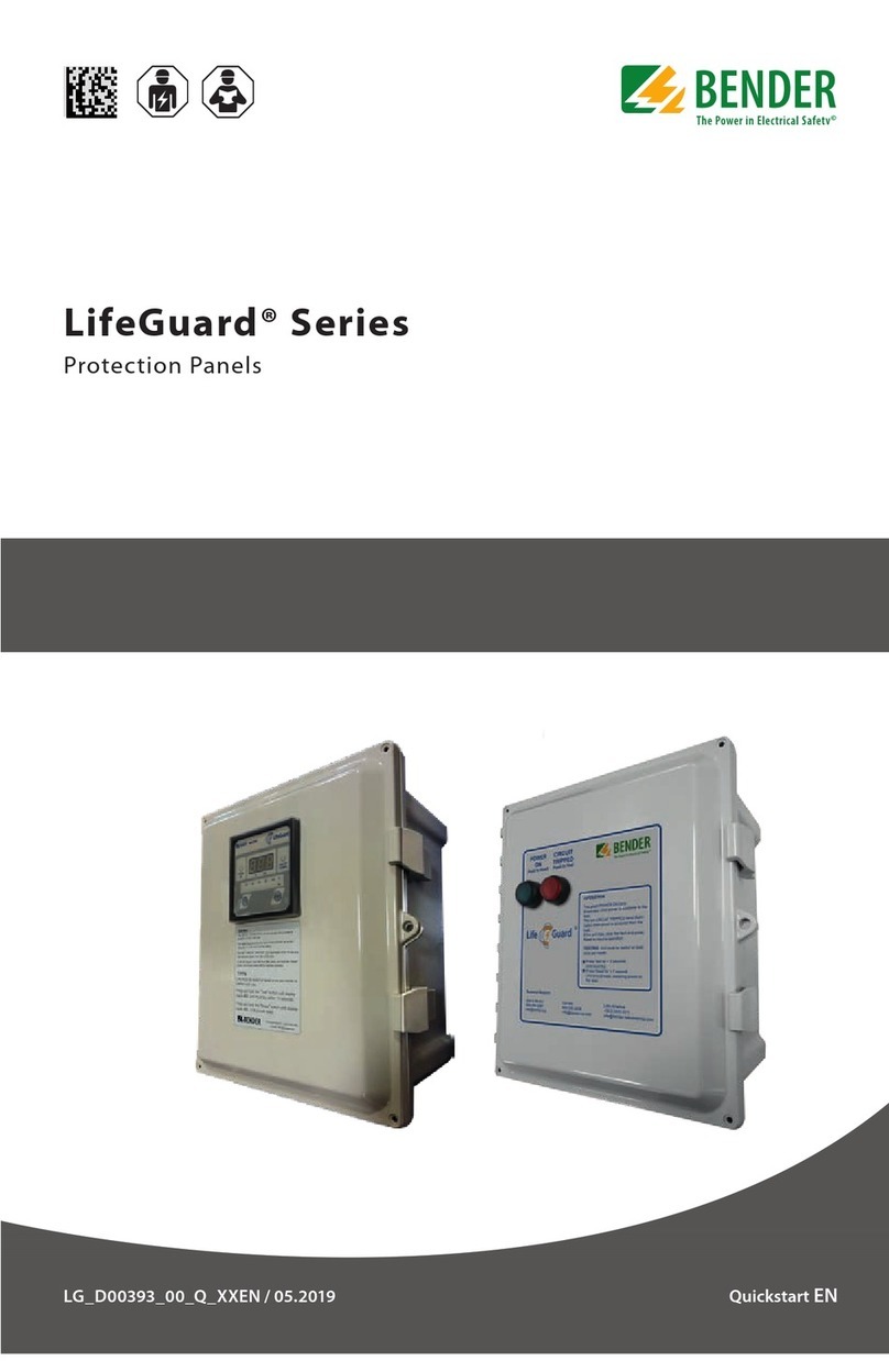
Bender LifeGuard GFGC protection panels are Listed Enclosed Industrial Control Panels
certified to UL 508A.
Ground fault detection: The internal ground fault detector RCMA421H extends the capa-
bility of standard ground fault monitors to detect ground fault current in both AC and DC
systems, as well as through all stages of power conversion, such as with variable frequency
drives. The RCMA421H combines a trip level of 6 mA with protection against nuissance
tripping through operation on an inverse time curve (per UL943, the standard for personnel
protection), as well as exceptional noise filtering.
Open ground detection: The internal ground continuity monitor GM420 adds an additional
layer of protection by continuously monitoring the integrity of the ground conductor
line. A wide adjustable range from 0.1 Ω to 100 Ω ensures the proper level of protection
for nearly every application. In addition, the GM420 monitors for extraneous voltages be-
tween its connection points.
Applications
• Loading docks
• Fueling stations
• Systems requiring frequent user connections/disconnections
Function
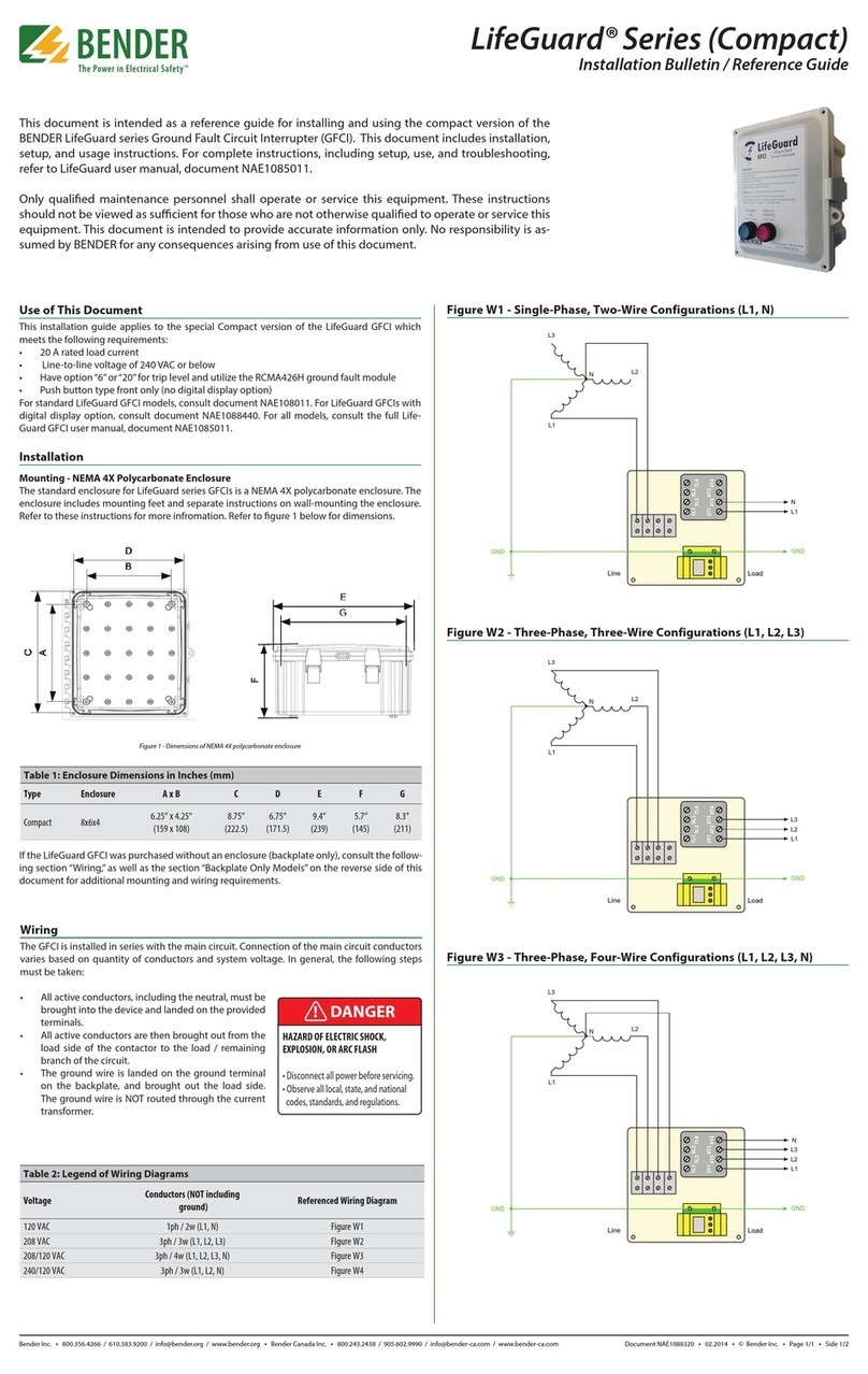
The GFGC series of panels is designed to interrupt power to a circuit when either a ground
fault or an open ground is detected. The entire solution is contained inside a NEMA 4
painted steel enclosure. Light indicators as well test/reset buttons on the front of the
enclosure allow for functionality without requiring access inside the panel. Settings are
preset; only a simple internal wiring is required.
When a ground fault is detected, the contactor will trip the main circuit based on an inverse
time curve (per UL943) relative to the preset 6 mA value. The inverse time curve assists in
alleviating potential nuissance tripping issues.
If an open ground is detected, the same contactor will trip the main circuit. The ground
continuity monitor utilizes a ground connection, as well as a field pilot wire connection
on the exterior of the enclosure. This connection is required for proper operation. The
open ground monitor will not allow the contactor to remain pulled in without a proper
field connection.
Universal Voltage 120…600 V
for Grounded AC Systems
Device adjustability and preset values
Type Adjustability Preset defaults
Ground fault, trip value 6 mA, xed 6 mA
Ground fault, time delay Inverse time curve Inverse time curve
Open ground, trip value 0.1…100 Ω3 Ω
Open ground, time delay 0…99 s 0 s

Ground Fault and Ground Continuity – Protection Panel GFGC
GFGC_D00395_00_D_XXEN/05.2019 3
Procedure for wiring GFGC assembly into system
• Locate the wiring diagram specific to the line voltage. Be sure
to select the voltage and phase type specific to the point at
where the GFGC panel is connecting.
• Connect the incoming lines to the contactor, being sure to have
all phases going through the WN-35BS current transformer (in-
cluding the neutral if one exists). Order of conductors is im-
portant.
When connecting to the contactor, placement of the neutral is
important. Connect the outgoing lines in the same manner.
Do not pass the ground conductor through the current
transformer or connect it to the contactor!
• Connect the incoming and outgoing ground wires to the
ground lug.
• Locate the control transformer. Terminal 1 (“Com. H2”) should
already be connected. Connect it if it is not.
• Connect the other wire to the terminal specific to the line volt-
age being protected. For instance, if the system is a 208/120 V
system, and the GFGC assembly is connected on the 208 V por-
tion of the circuit, connect the wire to the terminal labeled
“208.”
• Connect the ground pilot wire clamp to the connector on the
outside of the enclosure.
GFGC enclosure front (drawing not to scale)
Operation
The green POWER ON lamp illuminates when power is available to the load.
The red CIRCUIT TRIPPED lamp illuminates when power is removed from the load.
If unit has tripped, clear the fault and press Reset to resume operation.
Ground Fault Test
Unit must be tested at least once per month or before each use.
Press Test for >2 seconds. Unit must trip.
When unit trips a self test sequence starts. Wait >10 seconds.
Press Reset for >1 second. Unit should reset, restoring power to the load.
Ground Connection Monitor
Connect a pilot lead to the powered-equipment
ground and the connection located on the bottom of this enclosure. Loss
of this connection will cause loss of load power and the OPEN GROUND lamp to light.
Technical support: 1-800-356-4266
E-mail: [email protected]
Push To Reset
POWER
ON
CIRCUIT
TRIPPED
OPEN
GROUND
GROUND FAULT
GROUND CHECK
GFGC
Push To Test
Push To Test Lamp
1 - Power ON light/Reset pushbutton
Light illuminates when power is received to the device and not
in an alarm state.
Pushing the button for > 1 second resets the device.
(Must wait for test to complete!)
2 - Circuit tripped light/Test pushbutton
Light illuminates when the circuit has been tripped due to a
ground fault.
Pushing the button for > 2 seconds runs a test on the ground
fault detection unit.
3 - Open ground light/Light test pushbutton
Light illuminates when the ground continuity monitor has
detected an open ground.
Pushing the button runs a test on the open ground light.
1 2 3

Ground Fault and Ground Continuity – Protection Panel GFGC
4 GFGC_D00395_00_D_XXEN/05.2019
Wiring diagrams
120 V, single phase, with N (L, N)
208/120 V, three-phase, with N (L1, L2, L3, N)
208 V, three-phase, no N (L1, L2, L3)
240/120 V, single-phase, with N (L1, L2, N)
1L1 3L1 5L3 7L4
2T1 4T2 6T3 8T4
123 4 567
H2 Com. 120 V 208 V 240 V 277 V 480 V 600 V
Incoming Lines
Outgoing Lines
WN-35BS CT Contactor
Control Transformer
Always Connected
Connect Here
(120 V)
Pilot Wire Connection
(On exterior of enclosure)
To Clamp
L1 N
1L1 3L1 5L3 7L4
2T1 4T2 6T3 8T4
123 4 567
H2 Com. 120 V 208 V 240 V 277 V 480 V 600 V
Incoming Lines
Outgoing Lines
WN-35BS CT Contactor
Control Transformer
Always Connected
Connect Here
(208 V)
Pilot Wire Connection
(On exterior of enclosure)
To Clamp
L1 L2 L3 N
1L1 3L1 5L3 7L4
2T1 4T2 6T3 8T4
123 4 567
H2 Com. 120 V 208 V 240 V 277 V 480 V 600 V
Incoming Lines
Outgoing Lines
WN-35BS CT Contactor
Control Transformer
Always Connected
Connect Here
(208 V)
Pilot Wire Connection
(On exterior of enclosure)
To Clamp
L1 L2 L3
1L1 3L1 5L3 7L4
2T1 4T2 6T3 8T4
123 4 567
H2 Com. 120 V 208 V 240 V 277 V 480 V 600 V
Incoming Lines
Outgoing Lines
WN-35BS CT Contactor
Control Transformer
Always Connected
Connect Here
(240 V)
Pilot Wire Connection
(On exterior of enclosure)
To Clamp
L1 L2 N

Ground Fault and Ground Continuity – Protection Panel GFGC
GFGC_D00395_00_D_XXEN/05.2019 5
Wiring diagrams
277 V, single-phase, with N (L1, N)
480/277 V, three-phase, with N (L1, L2, L3, N)
480 V, three-phase, no N (L1, L2, L3)
600 V, three-phase, no N (L1, L2, L3)
1L1 3L1 5L3 7L4
2T1 4T2 6T3 8T4
123 4 567
H2 Com. 120 V 208 V 240 V 277 V 480 V 600 V
Incoming Lines
Outgoing Lines
WN-35BS CT Contactor
Control Transformer
Always Connected
Connect Here
(277 V)
Pilot Wire Connection
(On exterior of enclosure)
To Clamp
L1 N
1L1 3L1 5L3 7L4
2T1 4T2 6T3 8T4
123 4 567
H2 Com. 120 V 208 V 240 V 277 V 480 V 600 V
Incoming Lines
Outgoing Lines
WN-35BS CT Contactor
Control Transformer
Always Connected
Connect Here
(480 V)
Pilot Wire Connection
(On exterior of enclosure)
To Clamp
L1 L2 L3 N
1L1 3L1 5L3 7L4
2T1 4T2 6T3 8T4
123 4 567
H2 Com. 120 V 208 V 240 V 277 V 480 V 600 V
Incoming Lines
Outgoing Lines
WN-35BS CT Contactor
Control Transformer
Always Connected
Connect Here
(480 V)
Pilot Wire Connection
(On exterior of enclosure)
To Clamp
L1 L2 L3
1L1 3L1 5L3 7L4
2T1 4T2 6T3 8T4
123 4 567
H2 Com. 120 V 208 V 240 V 277 V 480 V 600 V
Incoming Lines
Outgoing Lines
WN-35BS CT Contactor
Control Transformer
Always Connected
Connect Here
(600 V)
Pilot Wire Connection
(On exterior of enclosure)
To Clamp
L1 L2 L3

Ground Fault and Ground Continuity – Protection Panel GFGC
6 GFGC_D00395_00_D_XXEN/05.2019
Installation troubleshooting tips
• The ground fault alarm trips instantly on a consistent basis.
Near-instant tripping may also indicate a serious ground fault in
the system.
Ensure that the following items are correct:
– The transformer and contactor are wired properly per the
above wiring diagrams based on the voltage being used.
– All phases (including the neutral if one is being used) are going
through the WN-35BS current transformer. Improper wiring
can cause an incorrect reading on the ground fault detector.
– The ground conductor must not pass through the current
transformer.
– There are no neutral-ground bonds downstream of the de-
vice. Having a neutral-ground bond downstream of the de-
vice will activate the grounded neutral protection alarm.
The panel must be reset manually via the door-mounted RESET
button in order to clear the trip.
• The ground fault alarm trips on a consistent basis, but not
instantly.
Ensure all of the above items are correct.
Ensure there are no ground faults on the system. A non-instant
trip is an indication that the total leakage current from many
different sources is adding up to approximately 6 mA. Consult
the manufacturer for more information and technical support.
• The open ground alarm trips on a consistent basis.
Ensure that the following items are correct:
– There is a proper pilot wire connection to the connector on
the outside of the enclosure.
– There is a proper connection between the clamp and the ve-
hicle/object.
– There are no broken ground connections in the system being
protected.
The panel must be reset manually via the door-mounted RESET
button in order to clear the alarm.
Installation troubleshooting tips (continued)
RCMA421H Ground Fault Monitor GM420 Ground Continuity Monitor
The RCMA421H is labeled with “IΔn” in the top right corner.
Possible messages displayed on the screen include:
• “X mA”: The amount of ground fault current (in mA) read by the
device.
• “E 01”: Connection alarm (consult the manufacturer if this alarm
appears).
• “E 02”: Connection alarm (consult the manufacturer if this alarm
appears).
If the RCMA421H has gone into the alarm state, and is not display-
ing an error code, follow these steps to retrieve the mA value:
• Hold the MENU button for > 1.5 s to enter the main menu.
• Press the down-arrow button until “HiS” (history) is reached.
Press the enter/MENU button.
Use this value to assist in determining the source of the ground fault.
If any error codes appear on the unit, consult the manufacturer for
more information.
The GM420 is labeled with “Ω LOOP” in the top right corner.
Possible messages displayed on the screen include:
• “X Ω”: The resistance of the loop in ohms.
• “OL”: Overload alarm (open connection).
If the GM420 goes into the alarm state, a reading of “X Ω” generally
indicates a present, but faulty ground connection. A reading of
“OL” generally indicates a nonexistant ground connection. Use these
values to troubleshoot the ground loop connection.
If any error codes appear on the unit, consult the manufacturer for
more information.

Ground Fault and Ground Continuity – Protection Panel GFGC
GFGC_D00395_00_D_XXEN/05.2019 7
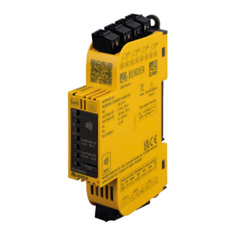
Technical data: Ground fault monitor RCMA421H-D-2 and current transformer WN-35BS
Insulation coordination acc. to IEC 60664-1/IEC 60664-3
Rated insulation voltage AC 250 V
Rated impulse voltage/pollution degree 2.5 kV/3
Protective Separation (reinforced insulation) between (A1, A2) - (k/l, T/R) - (21, 22, 24)
Voltage tests to IEC 61010-1 2.21 kV
Supply voltage
Supply voltage USAC/DC 70…300 V
Frequency range of US42…460 Hz
Power consumption ≤ 4.5 VA
Measuring circuit
External measuring current transformer WN-35BS
Rated voltage (current transformer) 2.5 kV
Rated frequency 0…150 Hz
AC/DC measuring range 0…40 mA
Relative percentage error ( 0…20 Hz) -33 %…+100 %
Relative percentage error ( 20…90 Hz) 0…- 33 %
Relative percentage error ( 90…150 Hz) ± 17.5 %
Operating value
Rated ground fault current 6 mA
Time behavior
Operating time tae per UL943 See diagram
Starting delay tOperating time tae + 3.2 s
Display and memory
Display range (measured value) 0…40 mA
Maximum operating error ( 0…20 Hz) -33/+100 %/± 2 digits
Maximum operating error ( 20…90 Hz) 0…20 %/± 2 digits
Maximum operating error (IΔ< 2 mA) ± 7 digits
Measured value memory capacity Measured alarm value set
Switching elements
Number of switching elements 1 SPDT contact
Operating principle, adjustable normally energized operation
Electrical service life under rated operating conditions 10,000 switching cycles
Contact data acc. to IEC 60947-5-1
Utilization category AC-13 AC-14 DC-12 DC-12 DC-12
Rated operational voltage 230 V 230 V 24 V 110 V 220 V
Rated operational current 5 A 3 A 1 A 0.2 A 0.1 A
Minimum contact load 1 mA at AC/DC ≥ 10 V
Fault memory behavior Latching operation
Connections
Connection type specification for Screw terminals
Rigid/flexible conductor sizes AWG 24…12/24…14
Stripped length 0.31…0.35 in (8…9 mm)
Tightening torque 0.36…0.44 ft-lb (0.5…0.6 N-m)
Connection type specification for Push-wire terminals
Rigid/flexible conductor sizes AWG 24…14
Flexible with core end sleeve AWG 24…16
Stripped length 0.39 in (10 mm)
Opening force 11.2 lb (50 N)
Test opening, diameter 0.1 in (2.1 mm)
Environment/EMC
EMC acc. to UL 943
Operating temperature - 31…+ 150 °F (- 35…+ 66 °C)
Climatic class acc. to IEC 60721
Stationary use (IEC 60721-3-3) 3K5 (except condensation and formation of ice)
Transport (IEC 60721-3-2) 2K3 (except condensation and formation of ice)
Long-time storage (IEC 60721-3-1) 1K4 (except condensation and formation of ice)
Classification of mechanical conditions IEC 60721
Stationary use (IEC 60721-3-3) 3M4
Transport (IEC 60721-3-2) 2M2
Long-time storage (IEC 60721-3-1) 1M3
General data
Operating mode continuous duty
Position of normal use display-oriented
Protection class, internal components (IEC 60529) IP30, NEMA 1
Protection class, terminals (IEC 60529) IP20, NEMA 1
Enclosure material polycarbonate
Screw mounting 2 x M4
DIN rail mounting acc. to IEC 60715
Flammability class UL94V-0
Documentation number D00395
Weight:
RCMA421H ≤ 0.33 lb (150 g)
WN-35BS ≤ 0.78 lb (355 g)
Inverse time curve operation (including contactor) per UL943
260220 240200180160140120100806040200
0,01
0,10
1,00
10,00
T/s
I/mA
6; 5,594
30; 0,560
264; 0,0250

Ground Fault and Ground Continuity – Protection Panel GFGC
8 GFGC_D00395_00_D_XXEN/05.2019
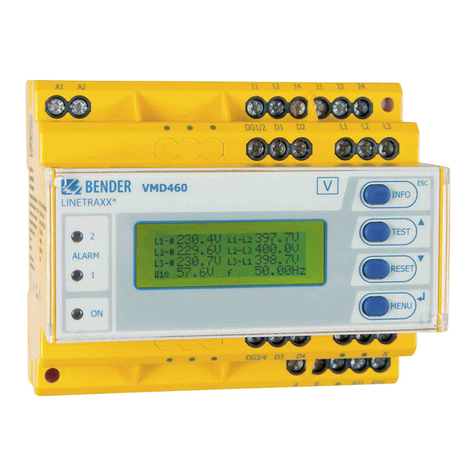
Technical data: Ground continuity monitor GM420
Insulation coordination acc. to IEC 60664-1/IEC 60664-3
Rated voltage AC 400 V
Rated impulse voltage/pollution degree 4 kV/3
Protective Separation (reinforced insulation) (A1, A2) - (E, KE) - (11, 12, 14) - (21, 22, 24)
Voltage tests to IEC 61010-1:
(E, KE) - [(A1, A2), (11, 12, 14)] 3.32 kV
(E, KE) - (21, 22, 24) 2.21 kV
(A1, A2) - (11, 12, 14) - (21, 22, 24) 2.21 kV
Supply voltage
Supply voltage USAC/DC 70…300 V
Frequency range of US15…460 Hz
Power consumption ≤ 3.5 VA
Measuring circuit
Loop resistance Rm
Measuring range Rm0…100 Ω
Measuring current ImDC 20 mA
Measuring voltage Um≤ DC 24 V
Extraneous voltage Uf
Measuring range UfAC 0…50 V
Rated frequency fn42…460 Hz
Measuring loop disconnection at Uf≥ 12 V
Measuring loop reconnection ≤ 10 V
Extraneous voltage Uf≤ 440 V
Permissible extraneous DC voltage without measurement influence DC 0 V
Response values
Loop resistance > Alarm 1 0.1…100 Ω
Resolution of setting R= 0…10 Ω0.1 Ω
Resolution of setting R= 10…100 Ω1 Ω
Time behavior
Start-up delay tAdjustable 0…99 s
Response delay ton1/2 Adjustable 0…99 s
Delay on release toff Adjustable 0…99 s
Operating time
tae in case of open loop connection (R > 50 kΩ) ≤ 40 ms
tae in case of closed loop connection (> R) ≤ 500 ms
tae in case of extraneous voltage (> V) and overload (OL) ≤ 100 ms
Response time tan tan = tae + ton1/2
Recovery time tan ≤ 300 ms
Recovery time tab after disconnection for safety reasons ≤ 1 s
Switching elements
Number of switching elements 2 SPDT contacts
Operating principle, adjustable normally energized or de-energized operation
Electrical service life under rated operating conditions 10,000 switching cycles
Contact data acc. to IEC 60947-5-1
Utilization category AC-13 AC-14 DC-12 DC-12 DC-12
Rated operational voltage 230 V 230 V 24 V 110 V 220 V
Rated operational current 5 A 3 A 1 A 0.2 A 0.1 A
Minimum contact load 1 mA at AC/DC ≥ 10 V
Fault memory behavior Latching or non-latching operation
Connections
Connection type specification for Screw terminals
Rigid/flexible conductor sizes AWG 24…12/24…14
Stripped length 0.31…0.35 in (8…9 mm)
Tightening torque 0.36…0.44 ft-lb (0.5…0.6 N-m)
Connection type specification for Push-wire terminals
Rigid/flexible conductor sizes AWG 24…14
Flexible with core end sleeve AWG 24…16
Environment/EMC
EMC IEC 61326
Operating temperature - 13…+ 131 °F (- 25…+ 55 °C )
Climatic class acc. to IEC 60721
Stationary use (IEC 60721-3-3) 3K5 (except condensation and formation of ice)
Transport (IEC 60721-3-2) 2K3 (except condensation and formation of ice)
Long-time storage (IEC 60721-3-1) 1K4 (except condensation and formation of ice)
Classification of mechanical conditions IEC 60721
Stationary use (IEC 60721-3-3) 3M4
Transport (IEC 60721-3-2) 2M2
Long-time storage (IEC 60721-3-1) 1M3
General data
Operating mode continuous duty
Mounting any position
Protection class, internal components (IEC 60529) IP30, NEMA 1
Protection class, terminals (IEC 60529) IP20, NEMA 1
Enclosure material polycarbonate
Screw mounting 2 x M4
DIN rail mounting acc. to IEC 60715
Flammability class UL94V-0
Weight ≤ 0.33 lb (150 g)
Technical data: GFGC panels
System voltage (universal) 120 , 208 , 208/120, 277, 480, 480/277, 600 V
Enclosure rating NEMA 4
Enclosure size, 30 A panel 12" x 12" x 6"
Enclosure size, 60 A and 100 A panel 16" x 12" x 6"
Fuse Rating Class CC Time Delay Fuse, 8/10 A, 600 VAC
Ground fault protection See RCMA421H technical data
Ground continuity protection See GM420 technical data

Ground Fault and Ground Continuity – Protection Panel GFGC
GFGC_D00395_00_D_XXEN/05.2019 9
Dimensions: GFGC-30 enclosure
Dimensions: GFGC-60 and GFGC-100 enclosure
12”
12”
12”
6”
6”
12”
16”
12”
12”
6”
16”
6”
Ordering Information
Load Ampere Rating Mfg. Reference No. Type Ordering Number
30 A LG30-600-120-3/4-4-PA-CH-XSLU GFGC-30 B541300044
60 A LG60-600-120-3/4-4-PA-CH-XSLU GFGC-60 B541300045
100 A LG100-600-120-3/4-4-PA-CH-XSLU GFGC-100 B541300046

GFGC_D00395_00_D_XXEN / 05.2019 / pdf / © Bender GmbH & Co. KG, Germany – subject to change! The specied standards take into account the edition valid until 05.2019 unless otherwise indicated.
USA & Mexico • Exton, PA • 800-356-4266/610-383-9200
Canada • Mississauga, ON • 800-243-2438/905-602-9990
Latin America • Santiago de Chile • +56 2 2933 4211
Your local contact:
This manual suits for next models
5
Table of contents
Other Bender Protection Device manuals
