Bender LifeGuard Series User manual

Quickstart EN
LG_D00393_00_Q_XXEN / 05.2019
LifeGuard® Series
Protection Panels

2 LG_D00393_00_Q_XXEN / 05.2019
LifeGuard® Series
LifeGuard® Protection Panels
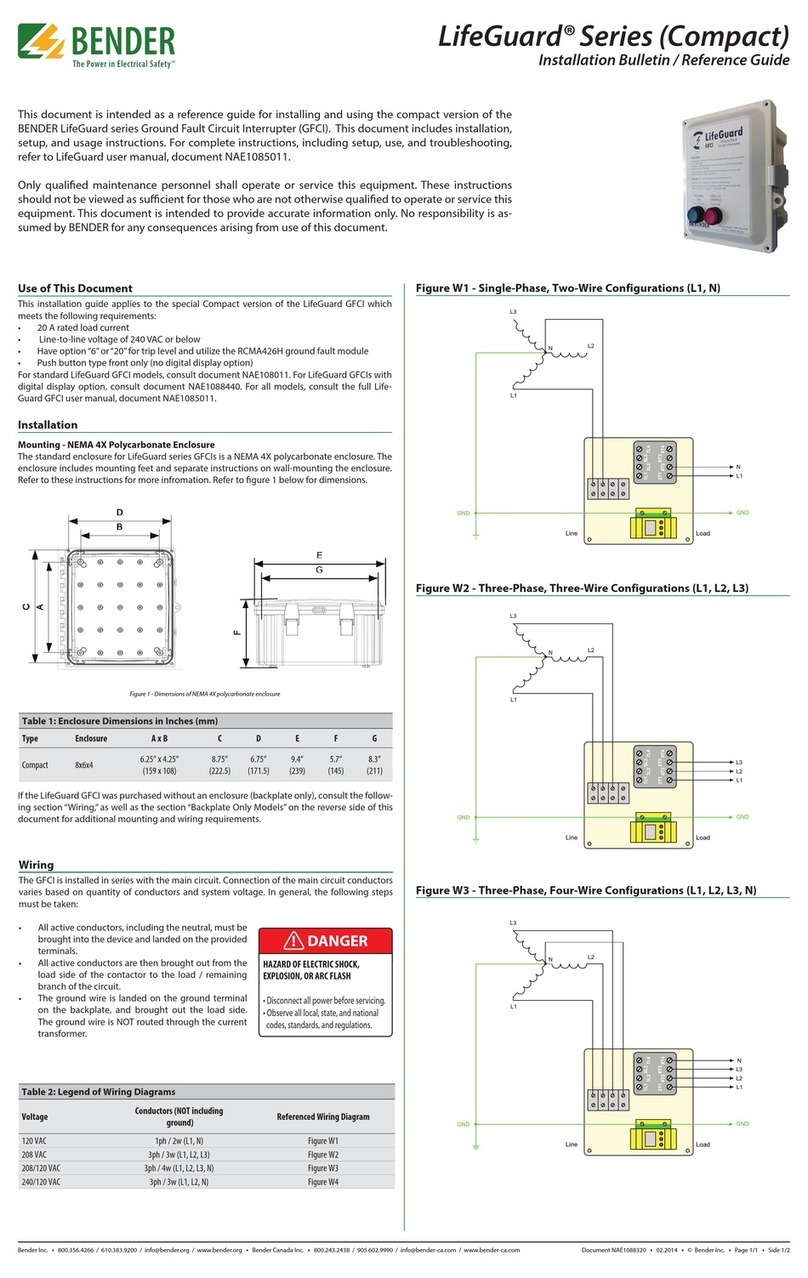
This document is intended as a reference guide for installing and using a Bender LifeGuard®
series protection panel. This document includes installation, setup, and usage instructions.
For complete instructions, including setup, use, and troubleshooting, refer to the LifeGuard
user manual available online at benderinc.com.
Only qualified maintenance personnel shall operate or service this equipment. These inst-
ructions should not be viewed as sufficient for those who are not otherwise qualified to
operate or service this equipment. This document is intended to provide accurate informa-
tion only. No responsibility is assumed by Bender for any consequences arising from use of
this document.
Use of this document
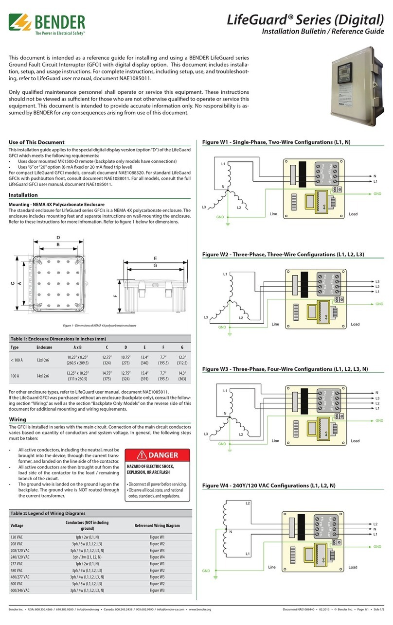
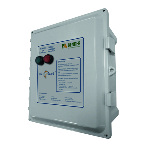
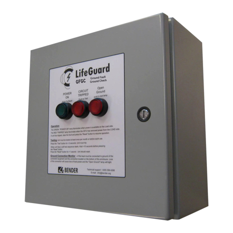
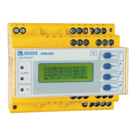
This quick start applies to standard LifeGuard models with push button / light front and
LifeGuard models with digital display and/or digital communication, as pictured above.
Standard model
Installation
Mounting - NEMA 4X Polycarbonate Enclosure
The standard enclosure for LifeGuard protection panels is NEMA 4X polycarbonate. The en-
closure includes mounting feet and separate instructions on wall-mounting the enclosure.
Refer to these instructions for more information. Refer to figure 1 below for dimensions.
A
G
E
C
F
B
D
H
Figure 1 - Dimensions of NEMA 4X polycarbonate enclosure
Table 1: Enclosure dimensions in inches (mm)
Type Enclosure A x B C D E F G H
< 100 A 12x10x6 10.25“ x 8.25“ 12.75“ 10.75“ 13.4“ 7.7“ 12.3“ 11.4
(260.5 x 209.5) (324) (273) (340) (195.5) (312.5) (290)
100 A 16x14x8 14.25“ x 14.25“ 16.75“ 14.75“ 17.4“ 9.7“ 16.3“ 15.4
(362 x 362) (425.5) (374.7) (442) (246) (414) (391)

LifeGuard® Series
LG_D00393_00_Q_XXEN / 05.2019 3
NEMA 4X Stainless Steel Enclosure (Order Code 5 4X-SS Option)
LifeGuard protection panels are available in a NEMA 4X stainless steel enclosure. The enclo-
sure includes separate instructions for wall-mounting the enclosure. Refer to those instruc-
tions for more information. Dimensions below are in inches (mm).
Type Enclosure A x B x C D x E G x H Y
Standard 16x12x6 12“ x 12“ x 6“ 14.2“ x 10.2“ 14.5“ x 10.5“ 8“
(305 x 305 x 152) (361 x 259) (368 x 267) (203)
100 A 20x16x8 20“ x 16 x 8“ 18.2“x 14.2“ 18.5“ x 14.5“ 10“
(508 x 406 x 203) (462 x 361) (470 x 368) (254)
If the LifeGuard was purchased without an enclosure (backplate only), consult the following
section “Wiring,” as well as the section “Backplate Only Models”.
Wiring
I HAZARD OF ELECTRIC SHOCK, EXPLOSION, OR ARC FLASH
- Disconnect all power before servicing.
- Observe all local, state, and national codes, standards, and regulations.
A professional electrician, licensed in accordance with local laws and regulations, must per-
form this installation. The enclosure must be penetrated in order to bring the line and load
conductors to the protective circuit. Bender recommends making these penetrations on
the bottom of the enclosure, and the use of NEMA 4X (minimum) fittings to maintain the
environmental rating of the enclosure. The specifics of the installation will dictate further
details.
Install the LifeGuard protection panel in series with the protected circuit. Circuit-conductor
connection varies based on the number of conductors and system voltage. Observe the fol-
lowing requirements during installation:
• Use copper wire only. For models rated less than 100 A, use 60 °C /140 °F (minimum) rat-
ed conductors. For 100 A rated models (or for systems where the required 60 °C conduc-
tor cannot be accepted), use conductors rated for 75 °C (167 °F).
• Disconnect switch, branch circuit protection, and/or overload relay to be provided by the
installer.

4 LG_D00393_00_Q_XXEN / 05.2019
LifeGuard® Series
• All active conductors, including the neutral, must be brought into the device through the
current transformer and connected to the line side of the contactor.
• All active conductors are then brought out from the load side of the contactor to the load
/ remaining branch of the protected circuit.
• Connect the line and load ground wires to the ground lug on the backplate. Do not route
the ground wire through the current transformer.
Voltage Conductors (NOT including ground) Referenced Wiring Diagram
120 VAC 1ph / 2w (L1, N) Figure W1
208 VAC 3ph / 3w (L1, L2, L3) Figure W2
208/120 VAC 3ph / 4w (L1, L2, L3, N) Figure W3
240/120 VAC 1ph / 3w (L1, L2, N) Figure W4
277 VAC 1ph / 2w (L1, N) Figure W1
480 VAC 3ph / 3w (L1, L2, L3) Figure W2
480/277 VAC 3ph / 4w (L1, L2, L3, N) Figure W3
600 VAC 3ph / 3w (L1, L2, L3) Figure W2
600/347 VAC 3ph / 4w (L1, L2, L3, N) Figure W3
Figure W1 -
Single-Phase, Two-Wire
Congurations (L1, N)
7L4
5L3
3L2
1L1
8T4
6T3
4T2
2T1
L1
L2
L3
N
Line Load
GND
Note 1
L1
N
GND
CT
Figure W2 -
Three-Phase, Three-Wire
Congurations (L1, L2, L3)
7L4
5L3
3L2
1L1
8T4
6T3
4T2
2T1
L1
L2
L3
N
Line Load
GND
Note 1
Note 2
L1
L3
L2
GND
CT

LifeGuard® Series
LG_D00393_00_Q_XXEN / 05.2019 5
Figure W3 -
Three-Phase, Four-Wire
Congurations (L1, L2,
L3, N)
7L4
5L3
3L2
1L1
8T4
6T3
4T2
2T1
L1
L2
L3
N
Line Load
GND
Note 1
L1
L3
N
L2
GN
D
CT
FigureW4 - Single-Phase
120/240 V Congurations
(L1, L2, N)
7L4
5L3
3L2
1L1
8T4
6T3
4T2
2T1
L1
L2
N
Line Load
GND
Note 1
Note 1 L1
L2
N
GND
CT
Note 1:Disconnect switch, branch circuit protection and/or overload relay to be provided by installer.
Note 2:Three-phase three-wire supplies can be solidly, or resistance grounded.
Additional Requirements - Backplate Only Models
This section only applies to LifeGuard models purchased without an enclosure and on
a backplate only. Refer to instructions below for additional requirements for installation
and wiring. Backplate-only models must be installed in a suitable enclosure.
Mounting - Backplate Only
Refer to Figure 3 below for dimensions. The unit must be mounted in a location sufficient
to protect live electrical equipment. Use four (4) #10 screws for mounting. It should be
placed X inches away from other equipment. This vertical clearance X (minimum depth of
enclosure, measured from the installed backplate) of the backplate is:
7L4
5L3
3L2
1L1
8T4
6T3
4T2
2T1
Note 1
Note 1
B
D
A
C
CT
Type A x B C x D
< 100 A 8.75“ x 10.75
(222 x 273)
8.25“ x 10.25“
(210 x 260)
100 A 12.75“ x 14.75“
(324 x 375)
12.25“ x 14.25“
(311 x 362)
• 6” (152 mm) for models less than 100 A
• 8” (203 mm) for 100 A models.
The mounting hole diameter is 3/8“ (9.5 mm).

6 LG_D00393_00_Q_XXEN / 05.2019
LifeGuard® Series
Use - Enclosure Front
Apply Power
To apply power, close the customer-supplied circuit breaker / disconnect on the line side of
the LifeGuard panel. If there are no ground faults present on the system, the green POWER
ON LED will light.
Perform Test (Trip Level Options A and F)
To perform a test on models with trip level option A or F, follow the instructions below.
• Push TEST for at least two (2) seconds.
• The unit will trip, the green POWER ON LED will go out, and the red CIRCUIT TRIPPED LED
will illuminate. Power to any connected loads will be interrupted.
• An internal self-test will initiate, taking approximately ten (10) seconds.
• Push RESET for at least one (1) second.
• If the internal self-test has completed, the unit will reset, the red CIRCUIT TRIPPED LED
will go out, and the green POWER ON LED will illuminate. Power will be restored to the
load.
Perform Test (Trip Level Options D and E)
To perform a test on models with trip level option D or E, follow the instructions below.
• Push TEST for at least two (2) seconds.
• The unit will trip, the green POWER ON LED will go out, and the red CIRCUIT TRIPPED LED
will illuminate. Power to any connected loads will be interrupted.
• Push RESET button for at least one (1) second.
• The unit will reset, the red CIRCUIT TRIPPED LED will go out, and the green POWER ON
LED will illuminate. Power will be restored to the load.
Field Adjustment, Error Codes and troubleshooting
Refer to LifeGuard user manual.
red
POWER LED / RESET button:
Illuminates when the panel has powerd and the
device has not tripped /
RESET button: Resets the panel if faults have been
cleared (momentary push).
green
TRIPPED LED / TEST button:
Illuminates when tripped /
TEST button: Performs a functional test
(hold for at least 2 seconds).
dashed
Emergency-stop button (OPTION“S”ONLY):
Pushing this button will disallow a start regard-
less of ground fault condition. Once pushed in it
needs to be pulled out and twisted for the panel
to resume normal function. This is only included in
models which end in“-S”
POWER
ON
Push to Reset
CIRCUIT
TRIPPED
Push to Test
OPERATION
The green POWER ON lamp
illuminates when power is available to the
load.
The red CIRCUIT TRIPPED lamp illumi-
nates when power is removed from the
load..
If the unit trips, clear the fault and press
Reset to resume operation.
TESTING Unit must be tested at least
once per month
Press Test for > 2 seconds.
Unit must trip.
Press Reset for > 1 second.
Unit should reset, restoring power to
the load.
USA & Mexico
800-356-4266
Canada
800-243-2438
Latin America
+56 2 2933 4211
Technical Support:
®

LifeGuard® Series
LG_D00393_00_Q_XXEN / 05.2019 7
Digital Display Option
Wiring - Control and Remote Indicator Wiring (Backplate Only)
This section applies to LifeGuard model numbers ending in “-N-D”. Follow the standard wir-
ing instructions shown above. Additionally, backplate-only models can be connected to ad-
ditional devices for remote capabilities. Enclosed models have the digital display prein-
stalled with no additional wiring required.
Test and reset functions are carried out in one of the following ways:
• Using the test and reset pushbuttons located directly on the RCMA-series ground fault
module.
• Connecting an optional MK1500-D remote indicator and using he built-in test and reset
buttons.
• Connecting an optional MK1500-D remote indicator and using t´s TEST, RESET, and T/R
terminals to connect external test and reset pushbuttons as shown in the drawing below.
The optional MK1500-D duplicates RCMA-module indication and test/reset pushbutton
functionality. Additionally, terminals are provided for external test and reset. Both are con-
figured for normally open (N.O.) contacts.
Observe the following additional requirements:
• Use shielded RS-485 cable, AWG 18 for connections “A” and “B.”
• The red switch labeled “R” on the underside of the ground fault module must be
switched to ON to ensure proper RS-485 termination. Standard RS-485 cable length lim-
itations apply.
• External test and reset control connections are optional and not necessary for the built-in
test and reset functionality of the MK1500-D and ground fault module.
• The MK1500-D requires an external supply voltage not supplied from the backplate, con-
nected to terminals A1 and A2. The supply voltage range is 100-240 VAC, 50/60 Hz.
Refer to the wiring diagram below. For additional information on installation and use of the
remote indicator, refer to MK1500-D installation manual.
MK1500
POWER
ON
CIRCUIT
TRIPPED
I mAI mA
%
25 50 75 100
TEST RESET
MK1500-D
i
Do not modify any other wiring on the
backplate when installing the remote.

Canada: Bender Canada Inc.
5810 Ambler Drive, Unit 1
Mississauga, ON L4W 4J5
Toll-Free: 800-243-2438
Phone: 905-602-9990 • Fax: 905-602-9960
E-mail: [email protected]
Web: www.bender-ca.com
LG_D00393_00_Q_XXEN / 05.2019/ pdf / © Bender GmbH & Co. KG, Germany – Subject to change!The specied standards take into account the edition valid until 05/2019 unless otherwise indicated.
All rights reserved.
Reprinting and duplicating
only with permission of the publisher.
USA: Bender Inc.
420 Eagleview Blvd.
Exton, PA 19341
Toll-Free 800-356-4266
Phone: 610-383-9200 • Fax: 610-466-2071
E-mail: [email protected]
www.bender.org
Use - Enclosure Front
Enclosed digital display units have a NEMA 1 enclosure rating.
Perform Test
• Press and hold the TEST button until display reads “tES.” An internal self-test will initiate.
Unit must trip within 15 seconds. Power to any connected loads will be interrupted.
• Press and hold the RESET button until display reads “rES.” Power will be restored to the
load side of the LifeGuard.
Field Adjustment, Error Codes and troubleshooting
LifeGuards with digital display utilize ground fault modules which are not field-adjustable.
They are fixed at a 6 mA trip level.
For digital display models, error codes will appear both on the internal ground fault module
and the door-mounted remote indicator.
Approvals
UL 508A Industrial Control Panels
MK1500
POWER
ON
CIRCUIT
TRIPPED
55
..
0
I mAI mA
%
25 50 75 100
TEST RESET
device
5.5.0 Digital display: Shows measured ground fault
current in real-time.
green POWER LED: Illuminates when the LifeGuard has
received power and has not tripped.
test TEST button: Performs a functional test
of the LifeGuard (instructions for use below).
red TRIPPED LED: Illuminates when the
LifeGuard has tripped.
LED bar LED bar graph: Indicates how close the
LifeGuard is to tripping.
reset RESET button: Resets the LifeGuard if faults have
been cleared (instructions for use below).
Table of contents
Other Bender Protection Device manuals
Popular Protection Device manuals by other brands
ABB
ABB RED615 ANSI Product guide
Max-Air Systems
Max-Air Systems ME G Series Installation, operation and maintenance instructions

Shipsonic
Shipsonic Heavy Duty Series Installtion Guide
American Innovations
American Innovations SurgeProtect Kit Quick reference guide

Image Diagnostics
Image Diagnostics Compass Product Line manual

Siemens
Siemens Reyrolle 7SR46 operating manual
