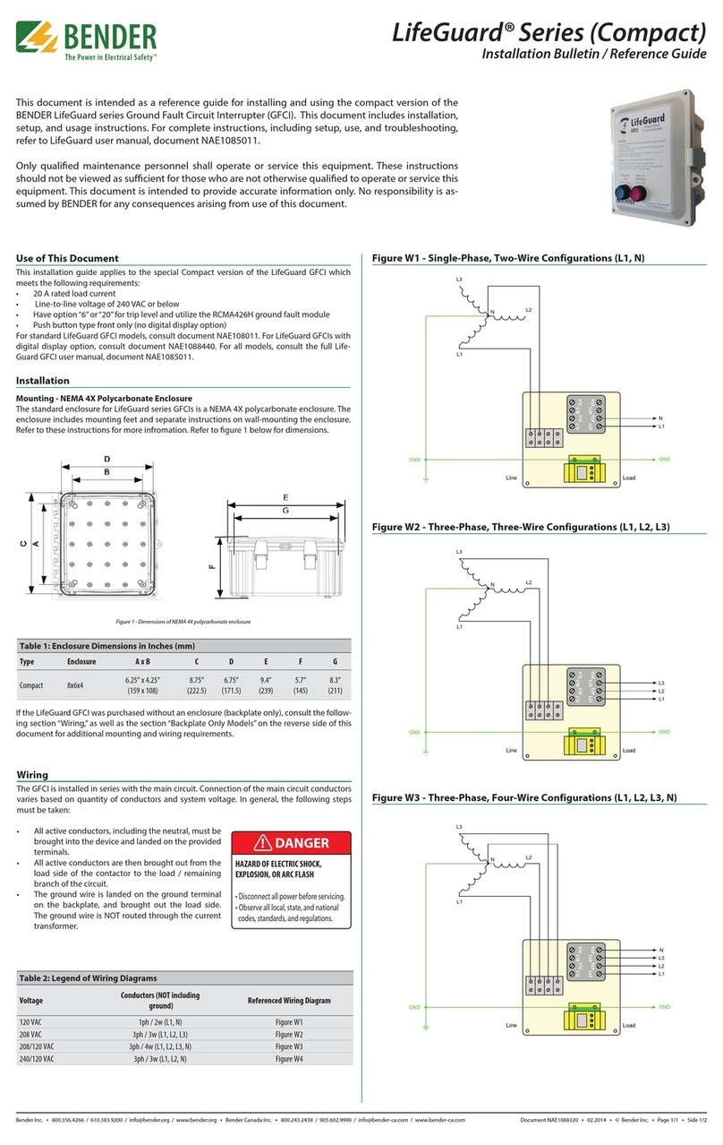
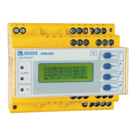
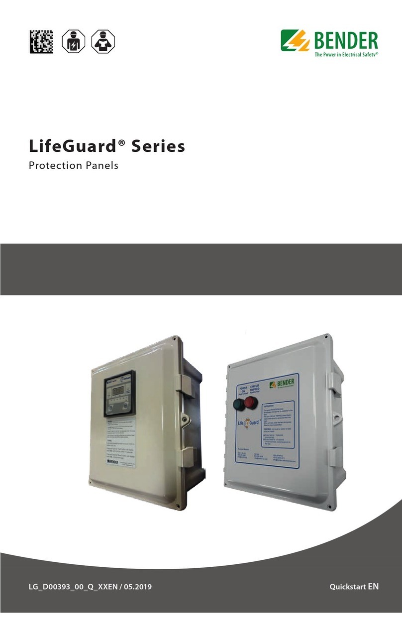
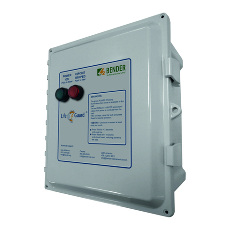
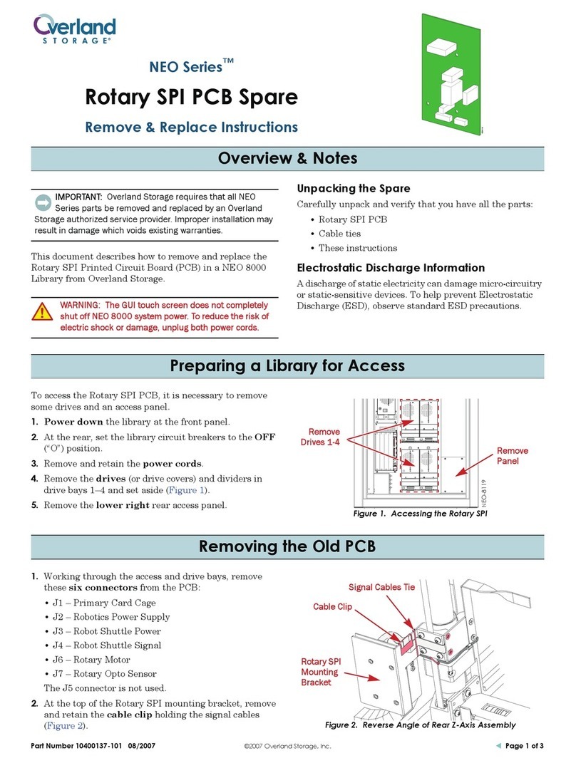
Bender LINETRAXX SmartDetect RCMS410 User manual

Manual ENRCMS410_D00424_00_M_XXEN / 09.2022
LINETRAXX® SmartDetect RCMS410
Four-channel DC, AC and pulse current sensitive residual current
monitor for earthed AC, AC/DC and DC systems

2 RCMS410_D00424_00_M_XXEN / 09.2022
Service and support for Bender products
First-level support
Technical support
Carl-Benz-Strasse 8 • 35305 Gruenberg • Germany
Telephone: +49 6401 807-760
0700BenderHelp *
Fax: +49 6401 807-629
E-mail: support@bender-service.de
Available from 7.00 a.m. to 8.00 p.m. 365 days a year (CET/UTC+1)
* Landline German Telekom: Mon-Fri from 9.00 a.m. to 6 p.m.: 6.3 cents/30 sec.;
remaining time: 6.3 cents/min.
Mobile phone: higher, depending on mobile phone tari
Repair service
Repair,calibration and replacement service
Londorfer Strasse 65 • 35305 Gruenberg • Germany
Telephone: +49 6401 807-780 (technical issues) or
+49 6401 807-784, -785 (commercial issues)
Fax: +49 6401 807-789
E-mail: [email protected]
Field service
On-site service
Telephone: +49 6401 807-752, -762 (technical issues) or
+49 6401 807-753 (commercial issues)
Fax: +49 6401 807-759
E-mail: eldservice@bender-service.de
Mon-Thu 7.00 a.m. to 4.00 p.m., Fri 7.00 a.m. to 1.00 p.m. (CET/UTC +1)

RCMS410_D00424_00_M_XXEN / 09.2022 3
LINETRAXX® SmartDetect RCMS410
Table of contents
1 General instructions .........................................................................7
1.1 How to use this manual..............................................................................................7
1.2 Indication of important instructions and information ...................................7
1.2.1 Signs and symbols........................................................................................................7
1.3 Training courses and seminars.................................................................................7
1.4 Delivery conditions.......................................................................................................7
1.5 Inspection, transport and storage ..........................................................................8
1.6 Warranty and liability...................................................................................................8
1.7 Disposal of Bender devices........................................................................................8
1.8 Safety.................................................................................................................................8
1.9 Intended use...................................................................................................................9
2 Function............................................................................................ 10
2.1 Device features ...........................................................................................................10
2.2 Functional description .............................................................................................10
2.2.1 Connection monitoring...........................................................................................11
2.2.2 Manual self test...........................................................................................................12
2.2.3 Malfunction ..................................................................................................................12
2.2.4 Delay times tb, t, ton, and toff ...................................................................................12
2.2.5 Factory settings FAC .................................................................................................13
2.2.6 Fault memory ..............................................................................................................13
2.2.7 Monitoring mode.......................................................................................................13
2.2.8 Preset function............................................................................................................14
2.2.9 Reload function...........................................................................................................14
2.2.10 NFC interface ..............................................................................................................14
2.3 Function modules......................................................................................................15
2.3.1 AC/DC-sensitive measuring and evaluation of values ................................15
2.3.2 Harmonic analysis (FFT)...........................................................................................15
2.3.3 Connection of Type A external transformers...................................................15
2.3.4 History memory (in preparation) ........................................................................15
3 Mounting and connection............................................................. 16
3.1 Mounting.......................................................................................................................16
3.2 Connecting the RCMS410.......................................................................................17
3.2.1 Connections overview .............................................................................................17
3.2.2 Wiring diagram ...........................................................................................................18
3.2.3 Supply voltage US ................................................................................................................................................................................... 18

4 RCMS410_D00424_00_M_XXEN / 09.2022
4 Interfaces .......................................................................................... 19
4.1 Digital inputs and outputs (overview) ...............................................................19
4.2 Output M+.................................................................................................................... 20
4.2.1 Digital mode ...............................................................................................................20
4.2.2 Analogue mode ......................................................................................................... 21
4.3 Digital input and output Q....................................................................................22
4.4 Digital input I ..............................................................................................................25
4.5 Inputs CT1…4..............................................................................................................26
4.5.1 Measuring-current-transformer connection ...................................................26
4.5.2 Connection of CTs of other manufacturers......................................................27
4.5.3 CT1…4 as digital input ...........................................................................................28
4.6 RS-485 interface..........................................................................................................28
5 Operation and settings on the device ........................................ 29
5.1 RCMS410 control panel (overview) ....................................................................29
5.2 STATUS LED.................................................................................................................. 29
5.3 ALARM LEDs.................................................................................................................30
5.4 CHANNEL-INDICATION LEDs..................................................................................30
5.5 T/R BUTTON..................................................................................................................30
5.5.1 "RESET" Function .......................................................................................................31
5.5.2 "TEST" function............................................................................................................ 31
5.5.3 "NFC" Function............................................................................................................ 31
5.5.4 "ADDR" function .........................................................................................................31
5.5.5. Harmonic analysis......................................................................................................32
6 Modbus interface............................................................................ 33
6.1 Overview........................................................................................................................33
6.2 Read and write permissions...................................................................................33
6.3 Data types.....................................................................................................................33
6.4 Register areas...............................................................................................................33
6.5 Device-information registers.................................................................................34
6.5 Alarm/measuring-value registers.........................................................................35
6.6 Monitoring-functions registers.............................................................................37
6.7 Status-information registers ..................................................................................37
6.8 Harmonic-analysis registers ...................................................................................38
6.9 THD, RMS registers, H1…400 ................................................................................ 42
6.10 Modbus-parameter registers................................................................................. 43
6.11 Registers of digital input "I"....................................................................................43
6.12 Registers of input/output "Q"................................................................................44
6.13 Registers of output "M+"......................................................................................... 45
6.14 Registers of response-value parameters ........................................................... 46
6.15 Function and operating-characteristics registers ..........................................47
6.16 Alarm-behaviour registers......................................................................................48

RCMS410_D00424_00_M_XXEN / 09.2022 5
LINETRAXX® SmartDetect RCMS410
6.17 Time-behaviour registers ........................................................................................48
6.18 Monitoring-functions registers.............................................................................48
6.19 Measuring-current-transformer registers .........................................................49
6.20 Device-error-code registers.................................................................................... 49
6.21 Control-commands registers................................................................................. 51
6.22 Function-control-commands registers ..............................................................51
7 Error – Cause – Error correction ................................................... 53
8 Technical data.................................................................................. 54
8.1 Frequency responses of the filters.......................................................................54
8.2 Tabular data ................................................................................................................56
8.3 Standards & certifications ....................................................................................... 57
8.4 Licences .........................................................................................................................57
8.5 EU Declaration of Conformity................................................................................57
8.6 Ordering information ...............................................................................................57

6 RCMS410_D00424_00_M_XXEN / 09.2022

RCMS410_D00424_00_M_XXEN / 09.2022 7
LINETRAXX® SmartDetect RCMS410
1 General instructions
1.1 How to use this manual
This manual is intended for qualified personnel working in electrical engineering and
electronics!
In addition to this manual, the enclosed "Safety instructions for Bender products" are part
of the device documentation.
Read the manual before mounting, connecting and commissioning the device.
Always keep the manual within easy reach for future reference.
1.2 Indication of important instructions and information
I Danger! Indicates a high risk of danger that will result in death or serious injury if not
avoided.
I Warning! Indicates a medium risk of danger that can lead to death or serious injury, if not
avoided.
I Caution! Indicates a low-level risk that can result in minor or moderate injury or damage to
property if not avoided.
i
Information can help to optimise the use of the product.
1.2.1 Signs and symbols
Disposal Recycling Temperature range
Protect from moisture Protect from dust RoHS directives
1.3 Training courses and seminars
www.bender.de > Know-how-> Seminars.
1.4 Delivery conditions
The conditions of sale and delivery set out by Bender apply. These can be obtained from Bender
in printed or electronic format.
The following applies to software products:
"Software clause in respect of the licensing of standard software as part of deliveries.
Amendments and modifications to general delivery conditions for products and services
in the electrical industry."
Die Elektroindustrie

8 RCMS410_D00424_00_M_XXEN / 09.2022
General instructions
1.5 Inspection, transport and storage
Check the shipping and device packaging for transport damage and scope of delivery. The follow-
ing must be observed when storing the devices:
1.6 Warranty and liability
Warranty and liability claims in the event of injury to persons or damage to property are excluded
in case of:
• Improper use of the device.
• Incorrect mounting, commissioning, operation and maintenance of the device.
• Failure to observe the instructions in this operating manual regarding transport, com-
missioning, operation and maintenance of the device.
• Unauthorised changes to the device made by parties other than the manufacturer.
• Non-observance of technical data.
• Repairs carried out incorrectly.
• Use of accessories and spare parts not recommended by Bender.
• Catastrophes caused by external influences and force majeure.
• Mounting and installation with device combinations not recommended by the manufac-
turer.
This operating manual and the enclosed safety instructions must be observed by all persons
working with the device. Furthermore, the rules and regulations that apply to accident prevention
at the place of use must be observed.
1.7 Disposal of Bender devices
Abide by the national regulations and laws governing the disposal of this device.
For more information on the disposal of Bender devices, refer to
www.bender.de > Service & Support.
1.8 Safety
If the device is used outside the Federal Republic of Germany, the applicable local standards and
regulations must be complied with. In Europe, the European standard EN 50110 applies.

RCMS410_D00424_00_M_XXEN / 09.2022 9
LINETRAXX® SmartDetect RCMS410
I Danger! Risk of electrocution due to electric shock!
Touching live parts of the system carries the risk of:
- An electric shock
- Damage to the electrical installation
- Destruction of the device
Before installing and connecting the device, make sure that the installation has been de-
energised. The rules for working on electrical systems must be observed.
1.9 Intended use
The RCMS410 device in conjunction with the specified measuring-current transformers (CT) is in-
tended for DC, AC, and pulsed DC sensitive residual-current measurement according to IEC
62020-1 .
Its area of application is the monitoring of residual currents IΔfor preventive maintenance in TN,
TT and IT systems with IΔ≤ 120 A peak, where IΔis intended to be measured within a range of f=
DC…20 kHz
The devices are intended for operation in control cabinets or similarly protected environments.
For intended operation, observe the specifications in this manual.
Any other use than that described in this manual is regarded as improper.

10 RCMS410_D00424_00_M_XXEN / 09.2022
Function
2 Function
2.1 Device features
• DC, AC, and pulsed-DC sensitive residual-current monitor type A, type F, type B and type
B+ according to IEC 62020-1 (depending on the connected measuring-current transfor-
mers and activated function modules)
• Four channels
• Functions for each channel: overcurrent (standard), undercurrent, or window function
(out-of-range-values)
• One digital input, one digital input/output and one multifunctional digital/analogue
output
• r.m.s. value measurement
• Residual operating current
– Type A: 6 mA…30 A
– Type F: 6mA…30A (15 Hz…20kHz)
– Type B/type B+: 10mA…10 A (only with function module "AC/DC
sensitive measuring and evaluation of values")
• Separate evaluation of AC/DC (RMS), AC, and DC
• Prewarning: 50…100 % of the residual operating current
• Supply voltage 24 V DC
• Alarm-LED for each channel
• Device status and Alarm LED
• Fault-memory behaviour selectable
• RS-485 with Modbus RTU
• NFC interface for device parameter setting via Bender Connect App with the device en-
gerised or de-energised
• Continuous CT-connection monitoring
• Expanded functions available by enabling these function modules:
– AC/DC sensitive measuring and evaluation of values
– Harmonic analysis (FFT)
– Connection of Type A external transformers
– History memory (in preparation)
2.2 Functional description
Once the supply voltage Ushas been applied and the recovery time tbhas elapsed, the start-up
delay tbegins. During the the start-up delay tno alarms are reported. Residual-current measure-
ment and evaluation is carried out via an external measuring-current transformer. If the measured
value exceeds or falls below the specified value for the prewarning and/or the residual operating
current, the response delay ton starts.
Alternatively, every measuring channel can also be configured as digital input. In this event, the
status of the digital input is output via the interfaces.
After ton has elapsed, a prewarning or a main alarm is given via the corresponding outputs and in-
terfaces, and the corresponding alarm LED lights up. If the value falls below the release value be-

RCMS410_D00424_00_M_XXEN / 09.2022 11
LINETRAXX® SmartDetect RCMS410
fore ton has elapsed, no alarm is signalled: The LEDs AL1, AL2 do not light up, and no prewarnung
or main alarm is signalled via an interface. The set release time toff starts when, after the alarm sta-
tus was triggered, the measured value again reaches the release value. Once toff has elapsed, the
device switches back to its initial status.
When the storing of a fault in the memory is enabled, the prewarnung or main alarm is given via
the interfaces and LEDs until a reset is performed. A reset can be carried out via the interface, the
digital input or the combined test/reset button (T/R).
The T/R button can also be used to test the device, to enable and disable the NFC function, and to
set the Modbus device address.
US
tbtae ton tae ton
t
IΔn1
IΔn2
IΔn
ON
Ch1…4
AL1
AL2
to to
tan
to
tan
LEDs
IΔ
t
Fig. 2–1 Timing diagram RCMS410
2.2.1 Connection monitoring
The connections to the measuring-current transformer are continuously monitored. In the event
of a fault, a message is output via the interfaces, and the status LED flashes yellow. After the fault
has been eliminated, the device automatically switches back to its initial status, and the status
LED lights up green. When the storing of a fault in the memory is enabled, alarm messages are
deleted only by a reset. Until then the status LED flashes yellow.

12 RCMS410_D00424_00_M_XXEN / 09.2022
Function
2.2.2 Manual self test
When the T/R-button is operated (3…6 s), the device simulates an alarm status. All LEDs are illu-
minated, and the outputs are activated. The alarm messages are output via the corresponding in-
terfaces. When the storing of a fault in the memory is enabled, the alarm LEDs and the outputs re-
main active until the fault memory is cleared by means of a reset.
i
Users need to carry out the manual self test periodically (at least.every 6 months).
2.2.3 Malfunction
In the event of an internal malfunction, the green status LED changes its colour to red or yellow.
The error code can be queried via the device interfaces.
2.2.4 Delay times tb, t, ton, and toff
The times tb, t, ton and toff described below delay the output of alarms via LEDs, digital outputs, and
Modbus RTU.
Recovery time tb
The recovery time is the time the device needs to be ready for measurement after connecting the
supply voltage Us.
Start-up delay t
After the supply voltage UShas been connected, the measuring function is delayed by the set
time t(0…999 s) plus the recovery time tb.
Response delay ton
If values exceed or fall below the defined residual-operating-current limits, the residual current
monitor requires the response time tan to output the alarm. A set response delay ton (0…10 s) is
added to the device-specific operating time tae and delays signalling:
Response time tan = tae + ton
If the fault does not persist during the response delay, the alarm is not signalled.
Delay on release toff
If the alarm no longer exists and the fault memory has been disabled, the alarm LEDs go out and
the device switches back to its initial status. By means of the delay on release (0...999 s), the alarm
state is maintained for the selected period.

RCMS410_D00424_00_M_XXEN / 09.2022 13
LINETRAXX® SmartDetect RCMS410
2.2.5 Factory settings FAC
There are two ways to carry out a reset:
Factory settings without interface
After restoring the factory settings, all previously changed settings are reset to the state upon
delivery. The settings for the Modbus interface are not reset.
Factory settings with interface
After restoring the factory settings, all previously changed settings including the settings for the
Modbus interface and the device address are reset to the state upon delivery.
i
These settings are configured in Modbus registers 60000…60003, function 4.
2.2.6 Fault memory
The storing of a fault in the memory can be enabled or disabled. When the fault memory is ena-
bled, stored alarms can be reset by performing a reset. The storing of a fault in the memory is fac-
tory-set to disabled.
2.2.7 Monitoring mode
For each channel for this mode either the overcurrent, undercurrent, or window function can be
selected.
• Overcurrent function
Prewarning when measured value > prewarning response value or
main alarm when measured value > residual operating current IΔn
• Undercurrent function
Prewarning when measured value < prewarning response value or
main alarm when measured value < residual operating current IΔn
i
Note that with the undercurrent function the response value of the prewarning is higher
than the residual operating current IΔn. See Modbus-register table for an explanation on
how to proceed.
• Window function An alarm is given when the values fall or rise outside the range
formed by the response value for a prewarning and IΔn.
i
The settings for this are configured in Modbus registers 32624…32635.

14 RCMS410_D00424_00_M_XXEN / 09.2022
Function
2.2.8 Preset function
With the adjustable preset function default values of the response values can be set for all chan-
nels. For this, the currently measured value is taken into account for every channel. The response
value is calculated by multiplying the currently measured value with a preset factor and then
adding a preset offset value.
IΔn = IΔx preset factor + preset offset
i
These settings are configured in Modbus registers 32713 and 32714.
2.2.9 Reload function
When faults occur only for a limited time but repeatedly in the monitored system while the stor-
ing of faults in the memory is disabled, the alarm outputs would switch over to the fault status si-
multaneously. The reload function permits limiting the number of these switch-overs. As soon as
the specified number is exceeded, the fault memory switches on, and a triggered alarm remains
stored. When an adjustable time period has passed between two alarms, the counter is reset
without the fault memory being switched on.
i
The settings for this are performed in Modbus registers
32418 and 32419 (input/output Q) or 32520 and 32521 (output M+).
2.2.10 NFC interface
The NFC interface can be used to transmit a previously configured device parameter setting di-
rectly to the RCMS410.
i
This function is available only via the Bender Connect App. You can find this app in the
Appstores for iOS and Android.
In the Bender Connect app the device first needs to be made known.
Then the device-specific setting options are shown so that they can be
configured. When the data is transferred, feedback is given whether the
parameter configuration has been successful.
The NFC antenna is located at the front on the righthand side of the
RCMS410. Parameter settings can be configurd via the Bender Connect
app by holding the mobile phone to the NFC logo at the front or at the
right sidewall.
To a de-energised device, a parameter setting can be transferred via the
Bender Connect app. This setting is then activated automatically when
the device is connected to the current supply.
Parameters can be configured via the Bender Connect App also when
the device is plugged in. To this end, the NFC interface first needs to be
activated in the device via the T/R button at the front of the device or
via the Modbus interface.

RCMS410_D00424_00_M_XXEN / 09.2022 15
LINETRAXX® SmartDetect RCMS410
2.3 Function modules
To expand its application range, optionally function modules can be enabled for the RCMS410.
These function modules can be ordered and activated both when first ordering the device and
also later on.
2.3.1 AC/DC-sensitive measuring and evaluation of values
All RCMS410 devices evaluate measuring-current transformers of the types "A" and "F". With this
function module also measuring-current transformers ot the types "B" and "B+" can be used.
i
With ordering numbers B84604041 and B84604042 the AC/DC-sensitive measuring and
evaluation of values is already enabled as a default.
2.3.2 Harmonic analysis (FFT)
This function module permits analysing harmonics.
i
With ordering number B84604042 the harmnoic analysis is already enabled as a default.
2.3.3 Connection of Type A external transformers
This function module permits the use of measuring-current transformers by manufacturers other
than Bender. When an external transformer is used, a winding number must be selected in the
corresponding Modbus register (33104…33107).
i
With ordering number B84604042 the incorporation of external transformers is already
enabled as a default.
2.3.4 History memory (in preparation)

16 RCMS410_D00424_00_M_XXEN / 09.2022
Mounting and connection
3 Mounting and connection
i
Only qualified personnel are permitted to carry out the work necessary to install, com-
mission and run a device or system.
I risk of electrocution due to electric shock! Touching live parts of the system carries the
risk of:
- A fatal electric shock
- Damage to the electrical installation
- Destruction of the device
Before installing and connecting the device, make sure that the installation has been de-
energised. The rules for working on electrical systems must be observed.
3.1 Mounting
64.0
48.5 1
18
8.75
65
100
111
109
93
45
Fig. 3–2 Dimensions diagram (in mm)

RCMS410_D00424_00_M_XXEN / 09.2022 17
LINETRAXX® SmartDetect RCMS410
3 Mounting and connection
i
Only qualified personnel are permitted to carry out the work necessary to install, com-
mission and run a device or system.
I risk of electrocution due to electric shock! Touching live parts of the system carries the
risk of:
- A fatal electric shock
- Damage to the electrical installation
- Destruction of the device
Before installing and connecting the device, make sure that the installation has been de-
energised. The rules for working on electrical systems must be observed.
3.1 Mounting
64.0
48.5 1
18
8.75
65
100
111
109
93
45
Fig. 3–2 Dimensions diagram (in mm)
Fig. 3–4 Connections of RCMS410–1
The cables are connected to the device via plug-in terminals. The maximum permissible conduc-
tor cross section is 1.5 mm².
Fig. 3–3 Mounting
3.2 Connecting the RCMS410
3.2.1 Connections overview
Screw mountingDIN rail mounting
< 2.5 mm
Ø M4
ISO7380-1, DIN84
Nm
1.0
100
1.
2.
2.
1.
Click!
Mounting Removal
S2
S1
S2
S1
S2
S1
S2
S1
CT4CT3CT2CT1
A
B
ON
+
–
Q
I
M+
24 V COM R I/O
Terminal Connection
Top
S1, S2 (CT4) Measuring-current transformer CT4
S1, S2 (CT3) Measuring-current transformer CT3
S1, S2 (CT2) Measuring-current transformer CT2
S1, S2 (CT1) Measuring-current transformer CT1
Bottom
+Supply voltage +24V DC
–
ARS-485 A - Modbus RTU
BRS-485 B - Modbus RTU
ON Termination of RS-485 interface
M+ Multifunctional output
QDigital output (congurable)
IDigital input
Ground

18 RCMS410_D00424_00_M_XXEN / 09.2022
Mounting and connection
3.2.2 Wiring diagram
Fig. 3–5 RCMS410 wiring diagram
Legend for wiring diagram
* For details see „4.6 RS-485 interface“
S1/S2 CT Measuring-current-transformer connection
S1/S2 DI CT1…4 as digital input
i
The RCMS410 and all connected CTUB102-CTBCxx devices must be supplied from the
same mains part.
i
Ensure that the 24-V-DC supply is connected correctly. Otherwise the RCMS410 can be
destroyed!
3.2.3 Supply voltage US
The device must be operated with a voltage of +24 V DC. The
connection is made at the bottom side of the device.
i
Only power supply units of protection class 2 or 3 shall be used.
RCMS410
S2
S1
S1/S2: DI
S2
L1 L2 L3 N
Verbraucher
Load
CT1…4
S1
S1 (k)
S2 (l)
S1/S2: CT
RS-485
B
A
R
–
+24 V
+
S1
S2 CT2
S1
S2 CT3
S1
S2 CT1
S1
S2 CT4
BA
R
–+
IQM+
S2
L1 L2 L3 N
Verbraucher
Load
S1
A1
US
~/+ ~/–
A2
RS-485
B
A
–
(+24 V
) optional
+
11
14
12
S1 (k)
S2 (l)
*

RCMS410_D00424_00_M_XXEN / 09.2022 19
LINETRAXX® SmartDetect RCMS410
4 Interfaces
4.1 Digital inputs and outputs (overview)
Element Explanation
M+
Multi-functional output
• Digital output: Signalling device states
• Analogue voltage or current output: For the direct connection of analogue instruments
that analyse and display measured values.
Q
Digital input/output
• Input Performing tests and/or resets
• Output Signalling device states
IDigital input
Performing tests and/or resets, can be congured with low-active and high-active.
Earth connection
i
During commissioning an output signal should be verified via an alternative route (e.g.
the Modbus interface or the behaviour of a different output.
When the analogue/digital outputs are used, redundant monitoring is always recom-
mended (for instance via the interface or a further output).
A
B
ON
+
–
Q
I
M+
24 V COM R
I/O

20 RCMS410_D00424_00_M_XXEN / 09.2022
Interfaces
4.2 Output M+
M+ is a multi-functional digital analogue output with reference to GND of the measuring sensor's
supply voltage.
4.2.1 Digital mode
Settings in registers 32500…32501
The following settings can be assigned to the output M+ in digital mode:
High-active: In the active mode +24 V are applied to output M+ internally.
RCMS410
M+
+
or
RCMS410
M+
+
Low-active: In the active mode the GND potential is applied to output M+.
RCMS410
M+
+
or
RCMS410
M+
+
In the passive mode ≤ 32V are connected externally (see technical data). The output switches the
applied potential to GND.
RCMS410
M+
+
or
RCMS410
M+
+
Permanently high: The output is permanently set to +24 V. In this manner e. g. an additional ref-
erence for the digital input can be created.
internally externally
I in max = 100 mA
RCMS410
M+
+
Other manuals for LINETRAXX SmartDetect RCMS410
1
Table of contents
Other Bender Protection Device manuals
