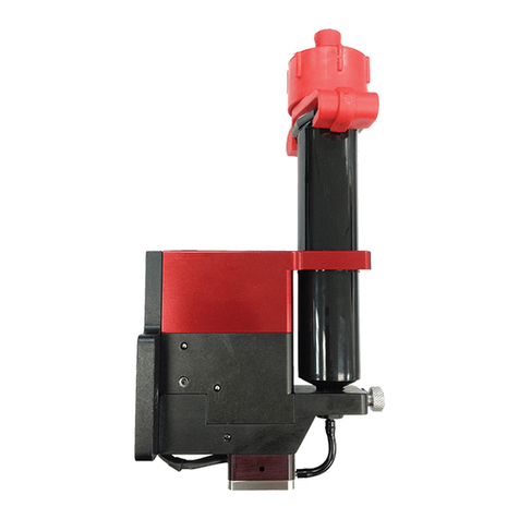
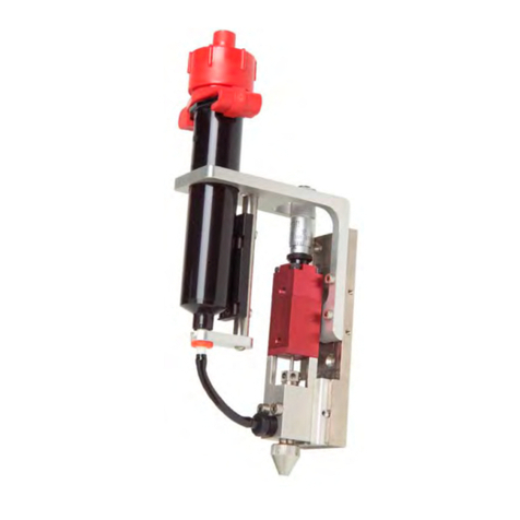
PVA SV200 User manual

SV200
SERVO DRIVEN AUGER STYLE
DISPENSE VALVE
Version: B12-3079
Operation Manual
SIX CORPORATE DRIVE
HALFMOON, NY 12065
PHONE: 518-371-2684
FAX: 518-371-2688
www.pva.net

SV200
Servo Driven Auger Style Dispense Valve
Thank you for purchasing the SV200 dispensing valve from PVA. Before
attempting to operate the SV200, we recommend that you take a few minutes and read
the following operation and setup manual. This will assist in familiarizing you with the
product and ensure a successful installation.
As always, if any questions or problems arise, do not hesitate to contact PVA’s
Valve Service Department for support. This department can be reached at PVA
headquarters via telephone or e-mail.
Again, thank you for your purchase, and we look forward to assisting you in the
future as you continue to improve your dispensing processes.
Theory of Operation
The SV200 uses a servo driven motor to rotate an auger inside the luer adapter of
the valve to provide a form of positive displacement control over fluid flow. Typical
applications include applying consistent bead patterns and dots of fluid where a high
degree of accuracy is required. With the quick release function of this valve, the motor
and auger assembly can be quickly removed from the luer adapter to clean the wetted
section. This valve is typically supplied with an SVC100 controller which is used to
program auger speed, dispense time, reverse time, and air pressure.
The SV200 has a divorced design comprising of two major sections. These include:
1) Servo Motor Drive (upper section)
2) Fluid Section (Red anodized aluminum and stainless steel)
The upper section is a servo drive motor used to accurately control the speed of
the auger screw and time that it rotates in the forward and reverse direction. The SCV100
controller has a digital display to select and program all parameters that will determine
fluid flow rate, shot size, and suck back.
The fluid section uses an aluminum retainer to house a stainless steel luer adapter
which acts as the fluid chamber. A screw type auger fits tightly inside to feed fluid
through to the dispense tip. The auger is connected directly to the servo motor and the rate
at which it is turned inside the luer adapter will determine fluid flow rate and dispense
volume. With little wear between the luer adapter and auger, this valve was originally
designed to dispense filled and abrasive pastes and fluids.
Wetted parts on the SV200 include:
- 304 stainless steel
- Aluminum, Red Anodized
- Viton, standard

Valve Options
The SV200 valve is available with a different thread pitch on the stainless steel
auger for high, medium, and low flow applications. Different size syringe mount inserts
are also available to support various diameter syringe barrels. A 30cc syringe adapter
support bracket is standard with the valve and inserts can be added for additional support.
Auger Options Valve Part #
8-Pitch(standard) SV200-08
16-Pitch SV200-16
Syringe Support Insert Insert Part Number
10cc Syringe 114-4139
5cc Syringe 114-4140
3cc Syringe 114-4141
1cc Syringe 114-4142

Safety
Due to material contents being under pressure eye protection is required for
operators. Refer to MSDS sheets on material being dispensed for other precautions.
Setup
Each SV200 auger valve requires an SVC100 controller for operation. A two pin
motor cable (23) is used to connect the controller and the valve to transfer the signal used
to rotate the auger. A second air output on the controller is used to supply air pressure to
the syringe of fluid only when the auger is spinning in the forward direction. Fluid is
typically supplied to the valve from a syringe mounted directly to the valve using the
disposable feed tube (20). PVA offers universal syringe air adapters that will connect the
syringe to the 5/32”od tube air output of the controller.

Tool Kit
PVA offers standard tool kits for all dispensing valves. The tool kit for the SV200
is part number B12-3419, which includes all necessary tools and lubricating grease to
perform maintenance on this dispense valve:
B12-3419 Includes:
Qty Part Number Description
1 0266244 8” Adjustable Wrench
2 V004 0.9 mm Allen Key
1 6958A21 1.5 mm Allen Key
1 7122A38 0.050” Allen Key
1 26559 1/16” Allen Key
1 26563 3/32” Allen Key
1 9570K71 Hook and Pick Set
1 B62-2048 Silicone Lubricant for O-Ring
1 114-5375 Press Tool
Operation
Refer to assembly drawing 112-4396 for part reference numbers.
1) Connect the valve to the controller as outlined above in the Setup procedures.
2) Cycle the valve and make sure the flexible coupling (17) and auger (14) spin in
the forward direction during dispense and the reverse direction when it stops.
3) Connect the syringe to the valve using the feed tube connector (20).
4) Mount a universal air cap to the syringe and connect the air line to the 5/32” tube
quick connect on the SVC100 controller.
5) Cycle the valve to the dispense position to feed material through the luer adapter
and purge all air.
6) Set the syringe air pressure to feed fluid to the auger.
7) Adjust the motor speed to the desired flow rate.
8) Adjust the reverse time to obtain a clean shutoff of fluid flow.
Note: Refer to Troubleshooting section for any problems.
Periodic Maintenance
The o-ring (18) mounted on the auger will need to be replaced as wear occurs.

End of Day Cleaning & Maintenance
The SV200 valve is designed with a quick connect feature to allow ease of
cleaning and disassembly of the wetted section of the valve on a daily basis. A spare parts
kit, part # SV2-08-SP or SV2-16-SP, is available with all the normal wear parts included.
1) Begin disassembly by disconnecting the motor cable (23) and syringe air adapter
from the valve assembly.
2) Disconnect the syringe of fluid from the feed tube (20).
3) Remove the feed tube (20) from the fluid body (1) and discard.
Note: The tapered plastic fitting of the feed tube is press fit into the fluid body.
4) Hold the valve body in one hand and press the disconnect bar (7) into the fluid
body (1) using your thumb. At the same time using your other hand, grab the top
of the servo motor (16) and pull the motor with coupling (17) and auger (14)
assembly out of the fluid section to completely remove it from the valve.
Note: There will be a spring force against the disconnect bar to force it away from
the fluid body.
5) Using a cloth, clean all material from the auger (14).
6) Then using a q-tip or other cleaning utensil wipe the luer adapter (15) and fluid
body (1) clean of all material.
7) Once the valve is clean it can be reassembled by again in one hand, hold the fluid
section and press the disconnect bar (7) into the fluid body (1). Once depressed,
the motor, coupling, and auger (16, 17, 14) assembly can be inserted back into the
fluid body.
8) Once the motor assembly (16, 17, 14) has been seated on the inside bottom of the
fluid body (1) the disconnect bar can be released to lock the assembly in place.
Note: You may need to press & wiggle the motor in place to allow the disconnect
bar to retract locking the assembly in place.
Complete Valve Disassembly
Cleaning and rebuilding the entire valve will be required from time to time. A
spare parts kit, part # SV2-08-SP or SV2-16-SP is available with all the normal wear
parts included.
1) Begin disassembly by disconnecting the motor cable (23) and syringe air adapter
from the valve assembly.
2) Disconnect the syringe of fluid from the feed tube (20).
3) Remove the feed tube (20) from the fluid body (1) and discard.
Note: The tapered plastic fitting of the feed tube is press fit into the fluid body.

4) Hold the valve body in one hand and press the disconnect bar (7) into the fluid
body (1) using your thumb. At the same time using your other hand, grab the top
of the servo motor (16) and pull the motor with coupling (17) and auger (14)
assembly out of the fluid section to completely remove it from the valve.
Note: There will be a spring force against the disconnect bar to force it away from
the fluid body.
5) Using a cloth, clean all material from the auger (14).
6) Then using a q-tip or other cleaning utensil wipe the luer adapter (15) and fluid
body (1) clean of all material.
7) Using a 0.9 mm Allen Key loosen the set screws of the flexible coupling (17) to
remove the auger (14) from the coupling then the coupling from the motor (16).
8) Using a Pick, remove the Viton o-ring (18) from the auger.
9) Then using a 1.5mm Allen Key, remove the 3 machine screws (19) that secure the
motor collar (4) to the motor (16) to separate those sections.
10)To disassemble the valve body, first use a 3/32” Allen Key to unthread and
remove the 4 machine screws (12) that secure the syringe holder (8) to the
standoffs (9) to remove the syringe holder.
11)Next, use an adjustable wrench to unthread and remove the standoffs (9) from the
fluid body (1).
12)To remove the luer adapter, use a press and press tool. First place the press tool
(114-5375) on the inside of the fluid body (1) on top of the luer adapter (15) and
push the luer adapter out of the fluid body.
13)If necessary, use a 0.050” Allen Key to unthread and remove the four machine
screws (11) from the valve body to remove the two quick disconnect covers (6)
and remove the components of the quick release mechanism.
Assembly Instructions
General
The o-ring (18) must be lubricated with a small amount of silicone grease.
A small amount of removable thread locker should be applied to the male threads of
the standoffs (9) and the male threads of the lock knobs (5).

Motor & Auger Assembly
1. Place the motor mount plate (4) onto the bottom of the servo motor (16) and
assemble using three machine screws (12) tightening with a 1.5 mm Allen key.
2. Thread the lock knobs (5) into the motor mount plate (4).
3. Slide the flexible coupling (17) onto the shaft of the servo motor (16) then use the
0.9 mm Allen key to tighten the two set screws on the flexible coupling to secure
it in place.
Note: Be sure one of the set screws are secured to the flat of the servo motor shaft.
4. Mount the o-ring (18) onto the auger (14) by sliding it over the top, non-threaded
portion of the auger.
Note: Do not slide the o-ring over the threads of the auger.
5. Insert the top, non threaded portion of the auger (14) into the coupling (17) and
secure it in place by tightening the two set screws using a 0.9 mm Allen key.
Note: be sure one of the set screws are secured to the flat of the servo motor shaft.
Fluid Body Assembly
1. Using a press and press tool (114-5375), place the press tool into the male side of
the luer adapter (15), align the inlet hole of the luer adapter to the inlet hole of the
fluid body (1) and press the two pieces together until the luer is inserted all the
way to the hard stop.
Note: After assembly, look through the inlet hole of the fluid body to verify the
holes are aligned properly.
2. Thread the four standoffs (9) into the fluid body (1) and tighten using an
adjustable wrench.
3. Place the syringe support (8) onto the standoffs (9) with the countersink away
from the standoffs and assemble using four machine screws (12) tightening with a
3/32” Allen key.
Note: The bracket should extend out on the same face as the port of the fluid body
4. Assemble the quick release assembly by first placing the release lock right (2)
component onto the fluid body (1) then inserting the spring (13) in place. Then
while holding the spring in place, assemble the quick disconnect cover (6) onto
the assembly and secure with the machine screws (11) using a 0.050” Allen Key
to tighten.
5. Repeat step 4 on the left side of the valve with the release lock left (3), spring
(13), quick disconnect cover (6), and machine screws (11).
6. Place the disconnect bar (7) in between the two release lock levers (2, 3) and
secure the assembly with the two machine screws (10) using a 1/16” Allen Key to
tighten.

Assemble Sections
1) Hold the fluid section in one hand then press the disconnect bar (7) into the fluid
body (1) using your thumb. Once depressed, the motor, coupling, and auger (16,
17, 14) assembly can be inserted through the syringe support bracket (8) and back
into the fluid body.
2) Once the motor assembly (16, 17, 14) has been seated on the inside bottom of the
fluid body (1) the disconnect bar can be released to lock the assembly in place.
Note: You may need to press & wiggle the motor in place to allow the disconnect
bar to retract locking the assembly in place.
Spare Parts
PVA offers standard spare parts kits for all dispensing valves. These kits are
stocked for immediate shipment and allow replacement of all wearable parts of the valve.
The spare parts kit for the SV200, product number SV2-08-SP or SV2-16-SP,
include the following components:
The 08 or 16 are used to specify the auger type.
Kit Includes:
Qty Part Number Description
1 Auger Pitch
- 114-2514 8 pitch
- V503-16 16 pitch
1 V504 Luer Adapter
3 V511 O-Ring
5 V507 Feed Tube
2 V004 Allen Key, 0.9 mm


BILL OF MATERIALS FOR SV200 (B12-3079)
Refer to Drawing #112-4396
Item Part Number Description Quantity
1 214-3131 Fluid Body, Aluminum 1
2 214-3139 Release Lock, Right 1
3 214-3142 Release Lock, Left 1
4 214-3145 Coupling Collar 1
5 214-3149 Lock Knob 2
6 214-3153 Quick Disconnect Cover 2
7 214-3161 Disconnect Bar 1
8 214-3163 Syringe Support Bracket, 30cc 1
9 214-3210 Standoff 4
10 SHCS 1-72 x 0.25 Socket Head Cap Screw 2
11 FHCS 1-72 x 0.25 Flat Head Cap Screw 4
12 SH5-40x0.375 Socket Head Cap Screw 4
13 V-92 Spring 2
14 114-2514 Auger, 8-pitch 1
15 V504 Luer Adapter 1
16 B12-3403 Servo Motor 1
17 V506 Flexible Coupling 1
18 V511 O-Ring, Viton 1
19 M2 x 6 Socket Head Cap Screw 3
Accessory Kit Supplied with Valve
20 V507 Feed Tube 5
21 V511 O-Ring, Viton 3
22 V004 Allen Key 2
23 VC108 Motor Cable 1

Troubleshooting
Problem Possible Cause Corrective Action
Valve does not
cycle - Motor not connected properly
- Cured material in fluid section - Check motor connections
- Disassemble valve and clean
Material leaks
from valve tip - Fluid pressure too high
- Not enough reverse on auger - Decrease inlet fluid pressure
- Increase reverse time on auger
Valve leaks from
mid-section - O-ring is worn - Replace O-ring
Valve does not
dispense
anything
- Fluid pressure is too low
- Cured material in fluid section - Increase fluid pressure
- Disassemble valve and clean
Air bubbles in
fluid - Valve not properly purged
- Air bubbles in syringe
- Reverse time set too high
- Cycle valve open to purge air
- Remove air from syringe
- Reduce reverse time
Dispense rate too
fast - Motor speed set too high - Decrease motor speed
Dispense rate too
slow - Motor speed set too low - Increase motor speed

PVA Warranty Policy
PVA warrants the enclosed product against defects in material or workmanship on
all components for one year from the date of shipment.
The warranty does not extend to components damaged due to misuse, negligence,
or installation and operation that is not in accordance with the recommended factory
instructions. Unauthorized repair or modification of the enclosed product, and/or the use
of spare parts not directly obtained from PVA (or from factory authorized dealers) will
void all warranties.
All PVA warranties extend only to the original purchaser. Third party warranty
claims will not be honored at any time.
Prior to returning a product for a warranty claim, a return authorization must be
obtained from PVA’s customer service department. Authorization will be issued either
via the telephone, facsimile, or in writing upon your request.
To qualify as a valid warranty claim, the defective product must be returned to the
factory during the warranty period. Upon return, PVA will repair (or replace) all
components found to be defective in material or workmanship.
(Retain this for your records)
Product Information:
PRODUCT: ______________________________
SERIAL NUMBER: ______________________________
DATE OF PURCHASE: ______________________________
This manual suits for next models
2
Table of contents
Other PVA Control Unit manuals
Popular Control Unit manuals by other brands

Neptune Systems
Neptune Systems AquaController Apex Classic Setup and Programming Guide

Joy-it
Joy-it DPS BT manual

GEM
GEM R477 Tugela operating instructions

Woodward
Woodward easYgen-1400 Operation manual

CIRCUIT DESIGN
CIRCUIT DESIGN CDP-RX-07M Operation guide

elsner elektronik
elsner elektronik MSG1 compact Technical specifications and installation instructions

Siemens
Siemens S5-155U System manual

Interlogix
Interlogix ATS7200E Installation sheet

Fireboy- Xintex
Fireboy- Xintex ESC Series Owner's Manual & Installation Instructions

LELY
LELY E-LINK D 6060 operating manual

Kohler
Kohler 28138T installation instructions

Watts
Watts Vision BT-CT02 RF Installation and user guide