9
ANTILOCK AND TRACTION WIRING
GENERAL NOTES
The wires that carry information and power into and out of
theEC-17™controller are generallygrouped and terminate
at a connector. The wire groups or wire harnesses along
withtheconnectorsare most oftenspecifiedand/orsupplied
by the vehicle manufacturer. The connectors used on the
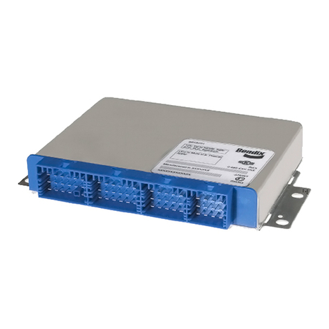
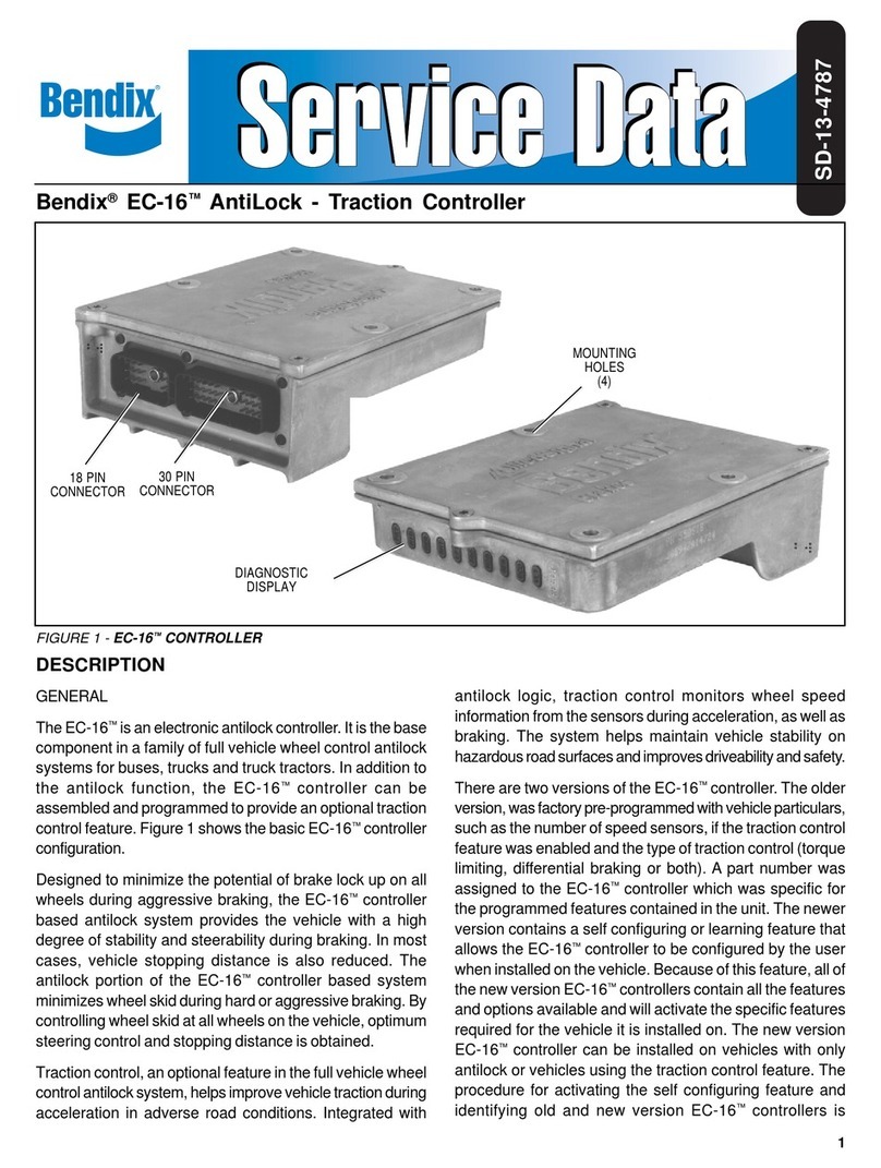
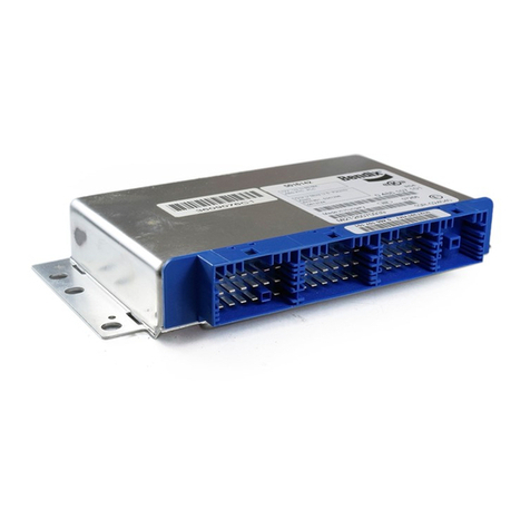
EC-17™controller are illustrated in Figure 5. The wiring
harnesses and connectors are weather resistant and the
wiresthat enter the connector are sealed to the connector.
Thewiregaugeusedin the wire harnessesisspecificto the
taskperformed.
Whendiagnosingwiringintheantilock system the following
generalrulesapplyandshouldbefollowedwhereapplicable:
1. Itisgenerallyadvisableto replace a wireharnessrather
than repair individual wires in the harness. If a splice
repair must be made, it is important that the splice be
properly soldered with a water based or thoroughly
cleanedrosinflux(notacidbased)andmadewaterproof.
2. Donotpiercewireinsulationwhencheckingforcontinuity.
Checkfor power,ground or continuityby disconnecting
theconnector and testingthe individual pins or sockets
inthe connector.
3. Donotspreadorenlargeindividualpinsorsocketsduring
probing.
4. Always check the vehicle handbook for wire and
connectoridentification.Individualwireidentificationwill
differ depending upon the type of connectors in use,
the vehicle manufacturer, and the system features in
use.
5. While the retarder disable, serial link, and traction on/off
connectionsarepresent on allEC-17™controllers, they
are not always used.
PREVENTIVE MAINTENANCE
Every3 months; 25,000 miles; or 900 operatinghours;
1. Check all wiring and connectors to ensure they are
secure and free from visible damage.
2. Althoughthe EC-17™controller incorporates self check
diagnostics, the optional LED display should be
inspectedtoensure that it isfunctional.With the vehicle
ignition on, a magnet (800 gauss; capable of picking
up 3 ounces) held to the LED reset switch (indicated
on the housing) should cause all of the LEDs to
illuminate. If one or more of the LEDs DO NOT
ILLUMINATE and the dash condition lamps indicate
the system is functioning properly, the non-illuminated
LED(s) should be noted for future reference. Although
the diagnostic capabilities will be limited, the system
will continue to function as designed.
3. Roadtest the vehicleby making anantilock stop froma
vehicle speed of 20 miles per hour. When an antilock
stop is made, the modulator solenoids pulsate and an
audibleburstofaircanbeheardfromoutsideofthecab.
Thewheelsshouldnotenteraprolonged"lock"condition.
Also,make a traction acceleration by accelerating ona
road surface with reduced traction. As with antilock,
audible bursts of air can be heard when the traction
system is functioning.
4. EC-17™controllers not equipped with an LED display
require the use of separate diagnostic tools capable of
using the S.A.E. J1587 diagnostic Link.
WARNING! PLEASE READ AND FOLLOW
THESE INSTRUCTIONS TO AVOID
PERSONAL INJURYOR DEATH:
When working on or around a vehicle, the following
general precautions should be observed at all times.
1. Park the vehicle on a level surface, apply the
parking brakes, and always block the wheels.
Always wear safety glasses.
2. Stop the engine and remove ignition key when
working under or around the vehicle. When
working in the engine compartment, the engine
should be shut off and the ignition key should be
removed. Where circumstances require that the
enginebeinoperation,EXTREMECAUTION should
be used to prevent personal injury resulting from
contact with moving, rotating, leaking, heated or
electrically charged components.
3. Do not attempt to install, remove, disassemble or
assemble a component until you have read and
thoroughly understand the recommended
procedures. Useonlytheproper tools and observe
all precautions pertaining to use of those tools.
4. If the work is being performed on the vehicle’s air
brake system, or any auxiliary pressurized air
systems,make certain to draintheair pressure from
all reservoirs before beginning ANY work on the
vehicle. If the vehicle is equipped with an AD-IS™
air dryer system or a dryer reservoir module, be
sure to drain the purge reservoir.
5. Following the vehicle manufacturer’s
recommendedprocedures,deactivatethe electrical
system in a manner that safely removes all
electrical power from the vehicle.
6. Never exceed manufacturer’s recommended
pressures.
7. Never connect or disconnect a hose or line
containing pressure; it may whip. Never remove a
component or plug unless you are certain all
system pressure has been depleted.
8. Use only genuine Bendix®replacement parts,
components and kits. Replacement hardware,
tubing, hose, fittings, etc. must be of equivalent
size, type and strength as original equipment and
be designed specifically for such applications and
systems.
