manuals.online logo
Brands
  1. Home
  2. •
  3. Brands
  4. •
  5. BENDIX
  6. •
  7. Controllers
  8. •
  9. BENDIX BRAKE CHAMBERS User manual

BENDIX BRAKE CHAMBERS User manual

1
Bendix Brake Chambers
SD-02-1302
CLAMPRING
PUSH ROD
ASSY.
CLAMPRING
NUTS & BOLTS
INLET PORT
NON
PRESSURE
PLATE
SPRING
INLET PORT
PRESSUREPLATE
DIAPHRAGM
DESCRIPTION
The brake chamber is a diaphragm type actuator which
converts the energy of air pressure into mechanical force.
Thediaphragm isheld betweenthe pressureplate andnon-
pressure plate by either a one piece clamp ring or a two
piece clamp ring (Figs. 1 and 2).
Different size brake chambers are identified by numbers
which specify the effective area of the diaphragm. A type
30 brake chamber has 30 square inches effective area.
Since one side of a brake chamber diaphragm is exposed
totheapplyingairpressureandtheothersidetoatmospheric
pressure,thechamber hasapressure and anon-pressure
side.Thenon-pressureplateisusuallyventedtoatmosphere
with four holes, however, on those installations where the
chamber must be weather-proof, venting is accomplished
throughadrilled passageinthe mountingboltsand therod
opening in the non-pressure plate is sealed by either a
bootoran o-ring seal.
Thestandarddiaphragm materialisa compoundofnatural
rubber with a fabric interior of nylon. Neoprene-nylon
diaphragmsareoptionally available.
Smaller chambers such as type 3 and type 6 have one 1/4
in.NPTinlet portinthe center ofthepressure plate.Larger
size chambers may have a center port and a side located
port or either one. Current production Type 20 chambers
and larger, generally have 3/8 in. NPT ports to facilitate
compliancewithFMVSS 121.
LOCK NUT
YOKE
MOUNTING
BOLTS
2
OPERATION
Controlled air pressure enters the brake chamber through
theinletportandacts uponthe diaphragmmovingthepush
plate and rod assembly forward.
Whenthebrakechamberisusedtoactuatecamtypebrake
foundationassemblies,theyoke (which is threadedonthe
push rod) is connected to a slack adjuster, which in turn is
connected to the brake cam shaft. This forward motion of
thepushrod rotatestheslack adjuster,camshaft andcam
applyingthevehicle brakes.
Thegreater airpressureadmittedtothebrakechamber,the
greater the force applied by the push rod and conversely,
the less pressure applied to the brake chamber the less
forceappliedby thepush rod.Pushrod forceis determined
by multiplying the delivered air pressure by the effective
diaphragmarea.Forexample,if 60psiisadmittedto atype
30 brake chamber, the lineal force on the end of the push
rod is approximately 1800 lbs.
Whenairpressure isreleasedfrom thebrakechamber,the
push rod return spring in combination with the brake shoe
return spring returns the diaphragm, push plate and rod
assembly, slack adjuster and brake cam to their released
positionsreleasingthe brakes.
PREVENTIVE MAINTENANCE
A. Every Month, 8,000 Miles or 300 Operating Hours,
depending on type of operation
1. Checkpushrod travelandadjust travel attheslack
adjusterifneeded.Pushrodtravelshouldbeasshort
aspossiblewithoutbrakesdragging.Excessivepush
rod travel reduces braking efficiency, shortens
diaphragm life, gives slow braking response and
wastesair.
2. Check push rod to slack adjuster alignment from
release to full stroke position to be sure push rod
moves out and returns properly without binding at
thenon-pressureplateholeor withother structures.
Also check the angle formed by the slack adjuster
armandpushrod.Itshouldbegreaterthan900when
thechamberisinthereleasedpositionand approach
900atmaximumre-adjustment stroke.
3. Checktightness ofmounting nuts.Checkcotterpins
to make sure they are in place.
4. Check all hoses and lines. They should be secure
andingood condition.
B. EveryYearoraftereach100,000Milesor3600Operating
Hours,dependingontypeof operation
1. Disassemble and clean all parts.
2. Install new diaphragm or any other parts if they are
worn or deteriorated. When the diaphragm, spring,
orbothare replaced,theyshould bereplacedin the
correspondingchamberon thesameaxle.
OPERATING AND LEAKAGE TESTS
A. OPERATINGTEST
1. Apply brakes and observe the push rods move out
promptlyandwithout binding.
2. Releasebrakesandobservethatthepushrodsreturn
tothereleasedpositionpromptlyandwithoutbinding.
3. Checkpushrod travel.Push rodtravelshould beas
short as possible without brakes dragging. Adjust
travel of push rod at slack adjuster if necessary.
B. LEAKAGETEST
1. Makeandhold a fullbrakeapplication.
2. Usingsoapsolution,coatclampingring(s).Ifleakage
is detected, tighten clamping ring only enough to
stopleakage.DO NOTOVERTIGHTENas thiscan
distort sealing surface or clamping ring. Coat area
aroundpushrodhole(loosenbootif necessary).No
leakage is permitted. If leakage is detected, the
diaphragmmustbe replaced.
REMOVING AND INSTALLING
A. REMOVING
1. Block vehiclewheels.
2. Release air pressure in all reservoirs.
3. Disconnect line to chamber.
4. Remove theyokepin.
5. Remove thebrake chamber.
CLAMP RING TYPE BRAKE CHAMBER DATA
(Dimensions in Inches)
Max. Max.Stroke
Stroke at Which
Effective * With Brakes
Area Outside Max. Brakes ShouldBe
Type (Sq. In.) Diameter Stroke Adjusted Readjusted
6 6 4-1/2 1-5/8 Should 1-1/4
9 9 5-1/4 1-3/4 be as 1-3/8
12 12 5-11/16 1-3/4 short as 1-3/8
16 16 6-3/8 2-1/4 possible 1-3/4
20 20 6-25/32 2-1/4 without 1-3/4
24 24 7-7/32 2-1/4 brakes 1-3/4
30 30 8-3/32 2-1/2 dragging 2
36 36 * * 2-1/4
*Dimensions listed do not include capscrew head
projectionsforrotochambers and boltprojectionsfor
clamp type brake chambers.
FIGURE 3

3
B.INSTALLING
1. Mountbrakechamber to mountingbracket.
2. Installyoke(if removed)andyoke pin.
3. Checktheangleformed bythecenterlineofthe push
rodandslackadjuster.Thisangle shouldbe greater
than 90° in the released position and approach 90°
at maximum readjustment stroke.
4. Connect line to chamber. Check to be sure hoses
areproperlysupported andclamped ifnecessaryto
provideproperclearance.
DISASSEMBLY
Cleanexteriorof brake chamberandmark parts inrelation
topositionto eachotherso that itmaybe assembledinthe
same way.
NOTE: If brake chamber is to be dismantled without
removing non-pressure plate from vehicle, slack
adjustershouldbebacked-off.
CLAMP RING TYPE CHAMBER
1. Pull out (or push out with air pressure) push rod and
clamp it at non-pressure plate. If using vise grip pliers,
push rod should be protected so that it will not be
damaged.
2. Remove clampringnuts andbolts.
3. If chamberhassingleclampring, spreadtheringslightly,
just enough to slip it off the plate. Care should be used
so that clamp ring is not distorted. If chamber uses two
piece clamp ring, remove clamp rings.
4. Remove pressureplate anddiaphragm.
5. Remove yoke lock nut and yoke from push rod and
release grip on push rod being careful to contain the
pushplate andnon-pressure plateuntil thereturn spring
loadisrelaxed.
6. Remove pushrodassembly andspring.
7. Removebootoro-ring(ifapplicable).
CLEANING AND INSPECTION
1. Clean all metal parts in cleaning solvent, removing all
rust and scale. All diaphragm sealing surfaces should
besmoothandclean.
2. Carefully inspectallmetal partsforcracks, distortionor
damage.
3. Replace all rubber parts and all other parts not
consideredserviceablewithgenuineBendixreplacement
parts.
ASSEMBLY
CLAMP RING TYPE CHAMBER
1. Stand push rod assembly upright on a flat surface.
2. Positionreturnspring onpushrod.
3. Installbootoro-ringonnon-pressureplate(ifapplicable).
4. Positionnon-pressureplateonpushrod,and pressplate
down against tension of spring until plate bottoms on
flat surface. Clamp rod with vise grips (protect rod) at
the plate.
5. If installingsingleclampring,positionringoverclamping
surface of non-pressure plate.
6. Check alignmentmarks(madebeforedisassembly)and
position diaphragm in pressure plate and place on
nonpressureplate.
7. If installing single clamp ring, work the clamp ring over
the clamping surface of the pressure plate and draw
theclamplugstogether with visegripsor a similar tool.
Install bolt and nut in clamp and tighten, tapping with a
soft faced mallet to center the clamp ring if necessary.
Releasegripon pushrodand installremainingbolt and
nut.
8. Install nuts and bolts evenly and only sufficiently to
eliminateleakage.
TESTING OF AREBUILT BRAKE CHAMBER
Perform tests outlined in “Operating and Leakage Tests”
section.
GENERAL SAFETY GUIDELINES
WARNING! PLEASE READ AND FOLLOW
THESE INSTRUCTIONS TO AVOID
PERSONAL INJURYOR DEATH:
When working on or around a vehicle, the
following general precautions should be
observed at all times.
1. Park the vehicle on a level surface, apply the
parking brakes, and always block the wheels.
Always wear safety glasses.
2. Stop the engine and remove ignition key when
working under or around the vehicle. When
working in the engine compartment, the engine
should be shut off and the ignition key should be
removed. Where circumstances require that the
enginebe inoperation,EXTREME CAUTIONshould
be used to prevent personal injury resulting from
contact with moving, rotating, leaking, heated or
electrically charged components.
3. Do not attempt to install, remove, disassemble or
assemble a component until you have read and
thoroughly understand the recommended
procedures. Useonly theproper toolsandobserve
all precautions pertaining to use of those tools.
4BW1426 © 2007 Bendix Commercial Vehicle Systems LLC. All rights reserved. 3/2007 Printed in U.S.A.
4. If the work is being performed on the vehicle’s air
brake system, or any auxiliary pressurized air
systems, make certain to drain the air pressure
from all reservoirs before beginning ANY work on
the vehicle. If the vehicle is equipped with an
AD-IS®air dryer system or a dryer reservoir
module, be sure to drain the purge reservoir.
5. Following the vehicle manufacturer’s
recommended procedures, deactivate the
electrical system in a manner that safely removes
all electrical power from the vehicle.
6. Never exceed manufacturer’s recommended
pressures.
7. Never connect or disconnect a hose or line
containing pressure; it may whip. Never remove a
component or plug unless you are certain all
system pressure has been depleted.
8. Use only genuine Bendix®replacement parts,
components and kits. Replacement hardware,
tubing, hose, fittings, etc. must be of equivalent
size, type and strength as original equipment and
be designed specifically for such applications and
systems.
9. Components with stripped threads or damaged
parts should be replaced rather than repaired. Do
notattempt repairsrequiring machiningor welding
unless specifically stated and approved by the
vehicle and component manufacturer.
10. Prior to returning the vehicle to service, make
certain all components and systems are restored
to their proper operating condition.
11. For vehicles with Antilock Traction Control (ATC),
theATC function must be disabled (ATC indicator
lampshould beON) priorto performinganyvehicle
maintenance where one or more wheels on a
drive axle are lifted off the ground and moving.

Other BENDIX Controllers manuals

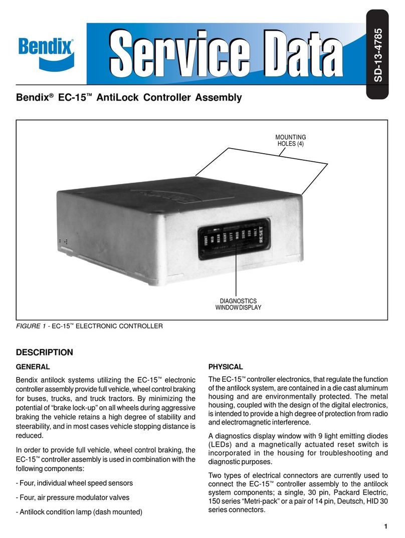
BENDIX EC-15 ANTILOCK CONTROLLER ASSY User manual

BENDIX

BENDIX EC-15 ANTILOCK CONTROLLER ASSY User manual

BENDIX EC-15 ANTILOCK CONTROLLER ASSY User manual

BENDIX

BENDIX EC-15 ANTILOCK CONTROLLER ASSY User manual

BENDIX EC-14 ANTILOCK CONTROLLER User manual

BENDIX

BENDIX EC-14 ANTILOCK CONTROLLER User manual

BENDIX EC-60 ABS Mounting instructions

BENDIX

BENDIX EC-60 ABS Mounting instructions

BENDIX ULTIMATE TOW Manual

BENDIX

BENDIX ULTIMATE TOW Manual

BENDIX EC-30 ABS-ATC CONTROLLER User manual

BENDIX

BENDIX EC-30 ABS-ATC CONTROLLER User manual

BENDIX EC-16 ANTILOCK CONTROLLER User manual

BENDIX

BENDIX EC-16 ANTILOCK CONTROLLER User manual

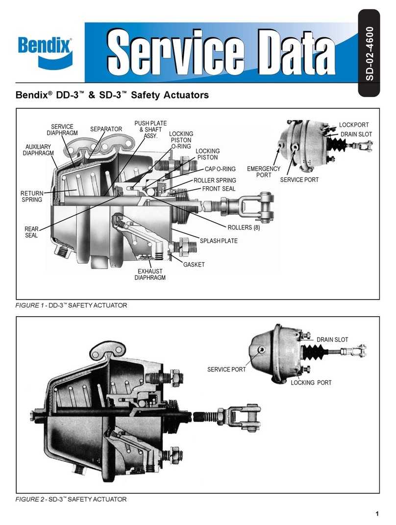
BENDIX DD-3-SD-3 SAFETY ACTUATORS User manual

BENDIX

BENDIX DD-3-SD-3 SAFETY ACTUATORS User manual

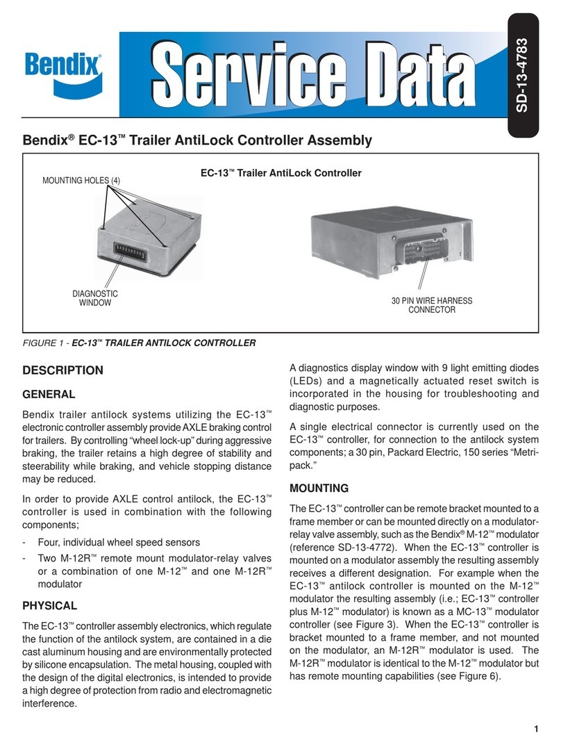
BENDIX EC-13 TRAILER ANTILOCK CONTROL User manual

BENDIX

BENDIX EC-13 TRAILER ANTILOCK CONTROL User manual

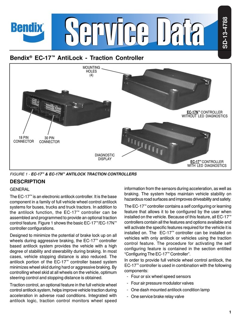
BENDIX EC-17 ANTILOCK TRACTION CONTROL User manual

BENDIX

BENDIX EC-17 ANTILOCK TRACTION CONTROL User manual

BENDIX MC-30 TRAILER ABS CONTROLLER User manual

BENDIX

BENDIX MC-30 TRAILER ABS CONTROLLER User manual

BENDIX EC-30 ABS-ATC CONTROLLER Operating instructions

BENDIX

BENDIX EC-30 ABS-ATC CONTROLLER Operating instructions

BENDIX EC-30 ECU User manual

BENDIX

BENDIX EC-30 ECU User manual

BENDIX EC-60 ABS-ATC ESP CONTROLLERS ADV Reference manual

BENDIX

BENDIX EC-60 ABS-ATC ESP CONTROLLERS ADV Reference manual

BENDIX EC-60 ABS-ATC ESP CONTROLLERS ADV User manual

BENDIX

BENDIX EC-60 ABS-ATC ESP CONTROLLERS ADV User manual

Popular Controllers manuals by other brands

Signcomplex LC-0RGB-WiFi-01 manual

Signcomplex

Signcomplex LC-0RGB-WiFi-01 manual

Hitachi EHV+ Series Applications manual

Hitachi

Hitachi EHV+ Series Applications manual

Trident Raider Installation and operation manual

Trident

Trident Raider Installation and operation manual

Mitsubishi Electric MELSEC Q Series user manual

Mitsubishi Electric

Mitsubishi Electric MELSEC Q Series user manual

Engineered air EngA W-TRAC Installation, operation and maintenance manual

Engineered air

Engineered air EngA W-TRAC Installation, operation and maintenance manual

Rockwell Automation CompactLogix series installation instructions

Rockwell Automation

Rockwell Automation CompactLogix series installation instructions

PRESONUS FaderPort 16 owner's manual

PRESONUS

PRESONUS FaderPort 16 owner's manual

Renkforce Joystick 1359969 operating instructions

Renkforce

Renkforce Joystick 1359969 operating instructions

Servomech Linearmech CLA 20 Installation, operation and maintenance manual

Servomech

Servomech Linearmech CLA 20 Installation, operation and maintenance manual

Allen-Bradley 2080-LC20-20QWB user manual

Allen-Bradley

Allen-Bradley 2080-LC20-20QWB user manual

Hayward HLXPLCONTROL installation manual

Hayward

Hayward HLXPLCONTROL installation manual

PCS PCS 4000 user guide

PCS

PCS PCS 4000 user guide

Barco EOS X Terminal user manual

Barco

Barco EOS X Terminal user manual

Bosch CRC200 quick start guide

Bosch

Bosch CRC200 quick start guide

Carel pCO compact PCOX000AA0 Technical leaflet

Carel

Carel pCO compact PCOX000AA0 Technical leaflet

Compaq StorageWorks 4100 - RAID Array troubleshooting guide

Compaq

Compaq StorageWorks 4100 - RAID Array troubleshooting guide

DEUTA Controls EnOcean-DALI BL-201-12-868 ERCO FLEX Assembly instructions and operating manual

DEUTA Controls

DEUTA Controls EnOcean-DALI BL-201-12-868 ERCO FLEX Assembly instructions and operating manual

Lunos Gesture Control 5/GS installation manual

Lunos

Lunos Gesture Control 5/GS installation manual

manuals.online logo
manuals.online logoBrands
  • About & Mission
  • Contact us
  • Privacy Policy
  • Terms and Conditions

Copyright 2025 Manuals.Online. All Rights Reserved.