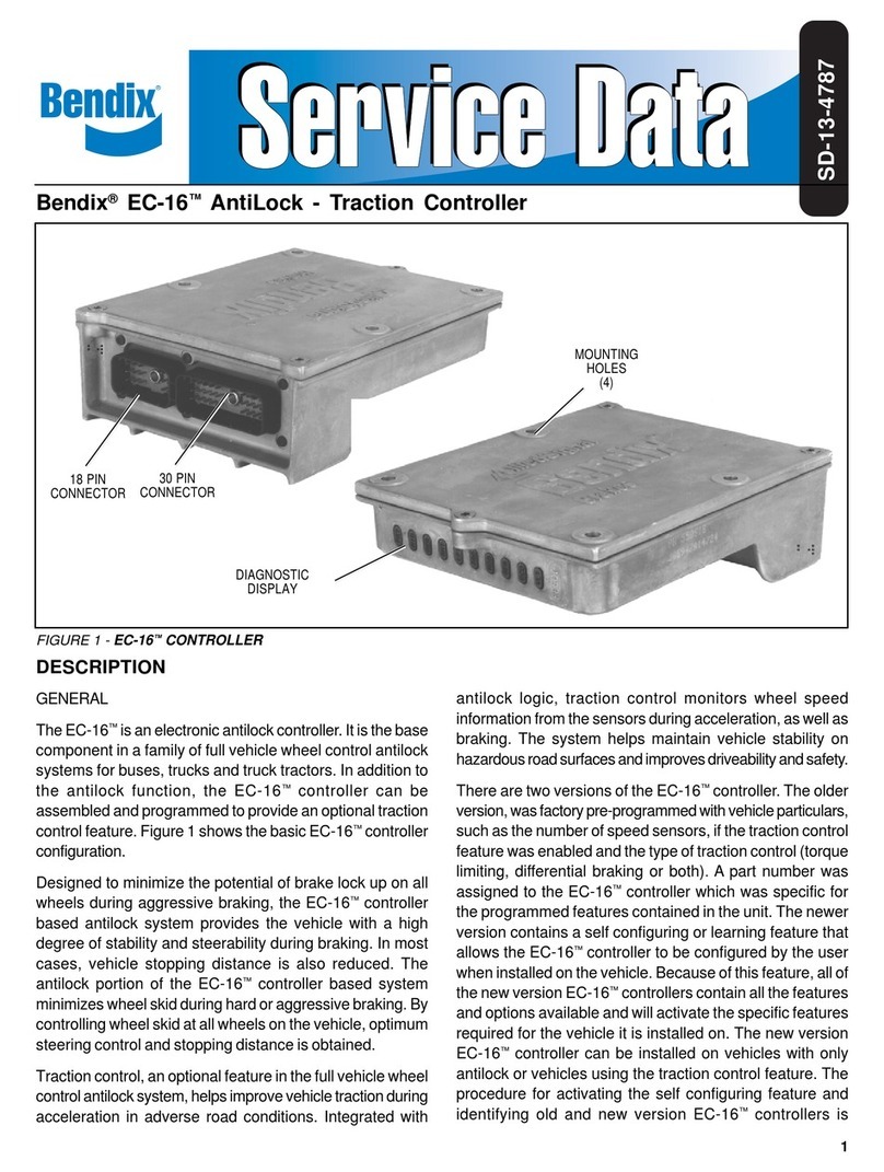
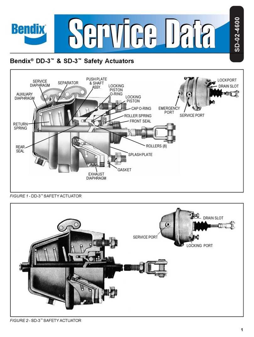
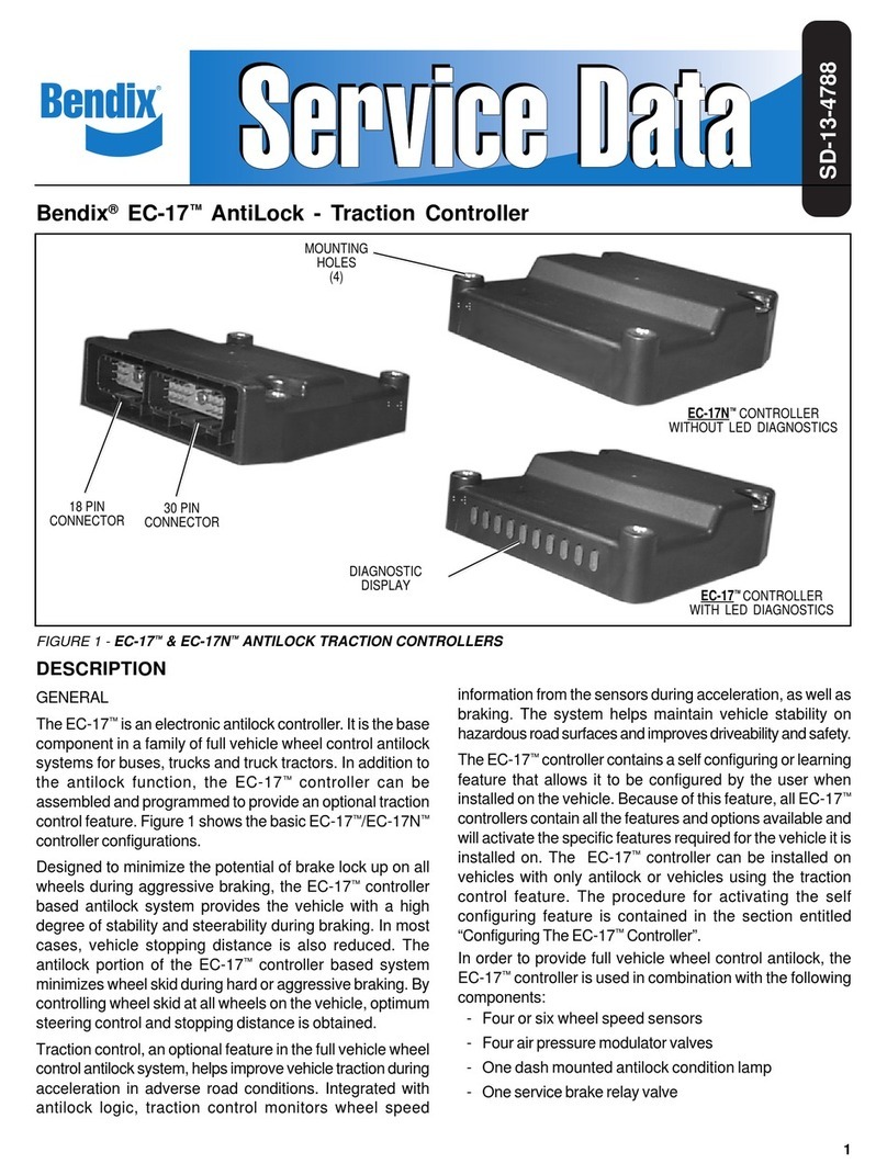
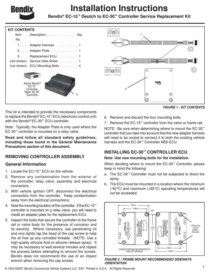
BENDIX EC-30 ABS-ATC CONTROLLER User manual

1
®
SD-13-4815
TABLEOFCONTENTS . . . . . . . . . . . . . . . . . . . . . . . PAGE
Introduction . . . . . . . . . . . . . . . . . . . . . . . . . . . . . . . . . . . 1
Components . . . . . . . . . . . . . . . . . . . . . . . . . . . . . . . . . . 2
Enclosure . . . . . . . . . . . . . . . . . . . . . . . . . . . . . . . . . . . . 2
Mounting . . . . . . . . . . . . . . . . . . . . . . . . . . . . . . . . . . . . . 2
EC-30™Controller Hardware Configurations . . . . . . . . 3
EC-30™Controller With PLC . . . . . . . . . . . . . . . . . . . . . . 3
EC-30™Controller Inputs . . . . . . . . . . . . . . . . . . . . . . . . 4
EC-30™Controller Outputs . . . . . . . . . . . . . . . . . . . . . . . 4
Power-Up Sequence . . . . . . . . . . . . . . . . . . . . . . . . . . . 6
ABS Operation . . . . . . . . . . . . . . . . . . . . . . . . . . . . . . . . 7
ATC Operation . . . . . . . . . . . . . . . . . . . . . . . . . . . . . . . . . 7
Auto-Calibration . . . . . . . . . . . . . . . . . . . . . . . . . . . . . . . 8
EC-30™Controller Configurable Parameters . . . . . . . . 8
EC-30™Controller Self-Configuration . . . . . . . . . . . . . . 8
Fault Detection . . . . . . . . . . . . . . . . . . . . . . . . . . . . . . . . 8
ABS Partial Shutdown . . . . . . . . . . . . . . . . . . . . . . . . . . . 9
EC-30™Controller Diagnostic Display . . . . . . . . . . . . . . 9
Blink Code Diagnostics . . . . . . . . . . . . . . . . . . . . . . . . 10
Bendix DCI Diagnostic Tool . . . . . . . . . . . . . . . . . . . . . 14
Bendix ABS Diagnostic Software . . . . . . . . . . . . . . . . . 15
NEXIQ (MPSI) Bendix Cartridge . . . . . . . . . . . . . . . . . . 15
Contacting Bendix . . . . . . . . . . . . . . . . . . . . . . . . . . . . . 15
Safe Maintenance Practices . . . . . . . . . . . . . . . . . . . . . 15
Removing the EC-30™Controller Assembly . . . . . . . . 16
Installing a New EC-30™Controller . . . . . . . . . . . . . . . 16
ABS andATC Wiring . . . . . . . . . . . . . . . . . . . . . . . . . . . 19
Troubleshooting . . . . . . . . . . . . . . . . . . . . . . . . . . . . . . 19
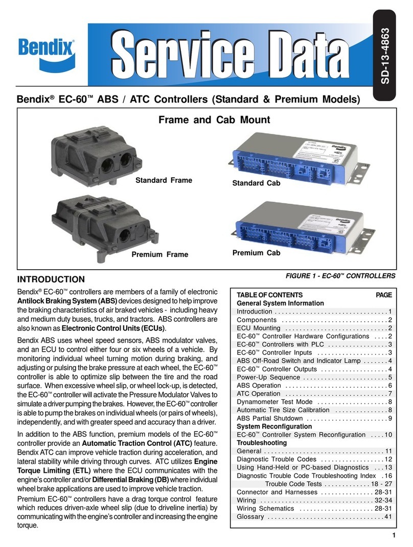
INTRODUCTION
TheBendix®EC-30™isanelectronicABS(antilockbraking
system) controller. It is the base component in a family of
ABSassembliesforheavyandmediumdutybuses,trucks
and tractors utilizing pneumatic braking systems.
The ABS function of the EC-30™controller is designed to
optimize slip on all vehicle wheels. The EC-30™controller
providesthe vehicle withimprovedstability and steerability
duringbraking. TheEC-30™controllerwillalsoreducevehicle
stopping distance on most surfaces.
In addition to the ABS function, the EC-30™controller can
beconfiguredtoprovideanATC(automatic tractioncontrol)
feature. Bendix ATC can improve vehicle traction during
acceleration on adverse road conditions. ATC can utilize
enginetorque limiting and/ordifferential braking toimprove
vehicletraction.
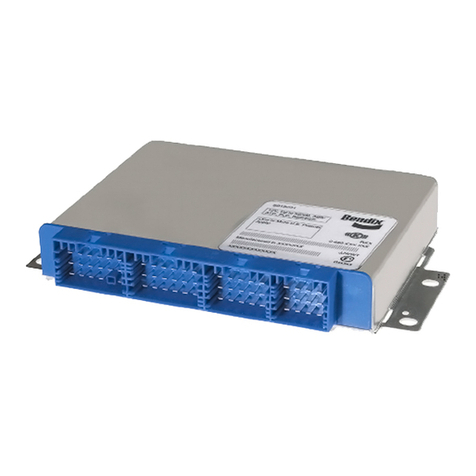
Bendix®EC-30™ABS / ATC Controller
FIGURE 1 - EC-30™CONTROLLER
18-pin
Connector
MountingInserts
(4 Places)
LEDDiagnostic
Display
30-pin
Connector
Part Number
Label

2
COMPONENTS
The EC-30™controller ABS function utilizes the following
components:
- Wheelspeedsensors(4or6,dependingonconfiguration)
- Electro-pneumaticABSmodulatorvalves(4)
- Dash mounted tractor ABS warning lamp (relay
controlled)
- Servicebrakerelayvalve
- DashmountedtrailerABSwarninglamp(towingvehicles
manufacturedafter March1, 2001)
- Blinkcode activation switch (optional)
The EC-30™controller ATC function utilizes the following
additionalcomponents:
- ATC modulator - Integral to the ATR (antilock/traction
relay)valveassembly
- DashmountedATCactive/warning lamp
- Serial communication to engine control module
(interfaceswith throttle inputand engine torque)
- ATCenable/disable switch
ENCLOSURE
The EC-30™controller electronics are contained in a non-
metallic housing and are environmentally protected by a
hard epoxy potting compound. The design of the EC-30™
controller electronics is robust against radio, electro-
magneticandenvironmental interference.
ApatentedLED (lightemittingdiode) diagnosticdisplayand
magnetic reset switch are incorporated in the housing for
simple,self-contained diagnostics.
The EC-30™controller utilizes a 30-pin and an 18-pin wire
harness to interface with ABS, ATC and vehicle system
components.
EC-30™Controller Comparison to EC-16™and
EC-17™Controllers
The EC-30™controller has been designed to replace the
EC-17™andthe EC-16™controllersasthe standardBendix
ABScontrollerforOEM and aftermarket installations. The
EC-30™controller has a black plastic enclosure similar to
the EC-17™controller. However, the EC-30™controller
utilizes plastic mounting inserts to reduce mounting bolt
corrosion, where the EC-17™controller utilizes metal
mounting inserts. The EC-16™controller utilizes a totally
metalenclosure.
TheEC-30™controllerABSwarninglamppower-upsequence
has been simplified compared to the EC-17™and EC-16™
controllers.
TheEC-30™controllerABSwarninglamp,atpower-upwithout
faults, will illuminate for 2.5 seconds and then turn off.
TheABS warning lampfor EC-17™and EC-16™controllers,
atpower-up without faults, will illuminatefor approximately
8seconds and flash twicebefore turning off.
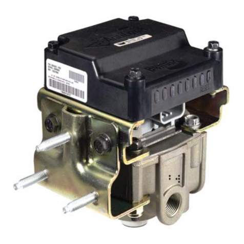
FIGURE 2 - EC-30™CONTROLLER WITH ATR VALVE
ATC
Modulator
Connector
ABS / ATC
Assembly EC-30™
Controller
ATC
Modulator
(integral)
ATRVALVE
EC-30™
Controller/Valve Added
Assembly ABS/ATR Function Vehicle
Models Valve Provided Application
CR-30 AR-1™Valve None All
CR-30BP AR-2™Valve BobtailBrake Tractors
Proportioning Only
AT-30 ATR-1™Valve ATC All
AT-30BP ATR-2™Valve ATC&Bobtail Tractors
BrakeProportioning Only
CHART 2 - EC-30™CONTROLLER / VALVE ASSEMBLIES
CHART 1 - ECU DIFFERENCES (EC-30™, EC-17™, EC-16™
CONTROLLERS)
ECU Enclosure ABS Warning Lamp
Model Power-Up Sequence
EC-30™Plastic with Plastic 2.5 seconds on, then off
Controller Mounting Inserts
EC-17™Plastic with Metal 8 seconds on, two
Controller Mounting Inserts flashes, then off
EC-16™Metal Enclosure 8 seconds on, two
Controller flashes, then off
MOUNTING
ECU Only
TheEC-30™controllercanbebracketmountedtothevehicle
cab or chassis as a stand alone ECU. See figure 1.
Valve Mounted EC-30™Controller
The EC-30™controller can be assembled on one of four
differentvalvemodels. Thecontrollervalveassemblyis then
mountedin place of the standard service brakerelay valve
onthevehicle. Anassemblymodeldesignationisassigned
when the EC-30™controller is mounted on anAR (antilock
relay) valve or anATR (antilock/traction relay) valve. See
figure2. Some modelsinclude bobtail proportioningand/or
ATC functions. See chart 2.

3
EC-30™CONTROLLER HARDWARE
CONFIGURATIONS
The EC-30™controller ABS ECU is available in different
hardware configurations in order to support various ABS,
ATCand power line carrier (PLC) features. See chart 3.
EC-30™controllerpremiumPLChardwarecanbeconfigured
forfour orsix sensors,withor withoutATC, andPLC canbe
disabled.
EC-30™controller basic models can not be configured for
six sensors orATC.
PLChardware is needed tosupport PLC communication.
Alwaysverify that you are workingwith the correct EC-30™
controllerby referring to thepart number label onthe ECU.
EC-30™CONTROLLER WITH PLC
EffectiveMarch 1,2001, alltowing vehicles mustcontrol an
in-cabtrailerABSwarninglamp. Trailersbuiltafterthisdate
willtransmit thestatusofthe trailerABSunitover thepower
line (blue wire of the J560 connector) to the tractor using
PLCcommunications.
The PLC signal is usually broadcasted by the trailer ABS
ECU. TheapplicationofPLCtechnologyfortheheavyvehicle
industry is known as PLC4Trucks. The Bendix®EC-30™
controllerpremiumwithPLC,andbasicwithPLC,willsupport
PLCcommunicationinaccordancewithSAE J2497.
Identifying an EC-30™Controller with PLC
AnEC-30™controller with or without PLCcanbeidentified
by the individual part number label on the ECU. Also, an
EC-30™controller may have one of the following labels
applied:
Measuring / Identifying the PLC Signal
An oscilloscope can be used to verify the presence of a
PLCsignalonthepowerline. ThePLCsignalisanamplitude
andfrequencymodulated signal. Dependingon thefiltering
and load on the power line, the PLC signal amplitude can
rangefrom 5.0mVp-p to 7.0Vp-p. Suggested oscilloscope
settings are (AC coupling, 1 volt/div, 100 µsec/div). The
signal should be measured at the power leads of the
EC-30™controller. See figures 3 & 4.
The EC-30™controller will not broadcast PLC messages
unless it is specially programmed to do so. With this
standardconfiguration,anABS trailerequipped withPLC or
aPLC diagnostictool will needto beattached to thevehicle
in order to generate a PLC signal on the power line.
1 Requiredfor all towing vehiclesbuilt after March 1, 2001.
CHART 3 - EC-30™CONTROLLER HARDWARE CONFIGURATIONS
FIGURE 3 - POWER LINE WITHOUT PLC SIGNAL
FIGURE 4 - POWER LINE WITH PLC SIGNAL
EC-30 Hardware Sensors ATC J1587 J1939 Blink J1922 J1939 PLC Trailer
Configurations Codes ABS WL1
Basic 4XXXX
Premium 4, 6 X X X X X
BasicPLC 4XXXXXX
Premium PLC 4, 6 X X X X X X X
EC-17/EC-16Service 4, 6 X X X X X X
Replacement
Diagnostics Engine
Communication
ECU does not support an in-cab
Trailer ABS warning lamp.
ECUsupports IN-CABTrailer
ABS warning lamp.
White Label:
Orange Label:

4
FIGURE 5 - BENDIX®WS-20™AND WS-24™WHEEL SPEED
SENSORS
EC-30™CONTROLLER INPUTS
Power and Ground
Poweris supplied tothe EC-30™controllerfromthe ignition
circuit through a 30 Amp fuse. The EC-30™controller is
groundedtothevehiclechassis. ForEC-30™controllerpower
andground connector pin locations,seeEC-30™controller
system schematic, Figure 14.
Wheel Speed Sensors
Wheelspeed datais providedto theEC-30™controller from
theBendix®WS-20™orWS-24™wheel speedsensors. See
figure 5 for wheel speed sensor illustrations. Working with
an exciter ring, wheel speed sensors provide the EC-30™
controller with an AC signal, which varies in voltage and
frequencyinrelation tothe speedofthe wheel. TheEC-30™
controller can be configured to receive wheel speed
informationfrom 100 or 86tooth exciter rings. Vehicle axle
configurations andATC features determine the number of
speed sensors that must be used. A vehicle with a single
reardriveaxle(4x2,4x4or6x2) requiresfourspeed sensors
for both ABS and ATC operation. A vehicle with two rear
drive axles (6x4) can utilize six speed sensors for optimal
ABS and ATC performance. For wheel speed sensor
connector pin locations, see the EC-30™controller system
schematic, Figure 14.
Blink Code Switch
The EC-30™controller can be configured to support an
optional diagnostic blink code switch to ground, which can
beusedto activateseveral functionsavailablethrough blink
code diagnostics. Pin F3, of the 30-pin connector, is the
blink code switch input.
Three Position Switch for ATC and Blink Codes
TheEC-30™controllercan beconfiguredto receiveboththe
ATCenable/disablesignalandtheblinkcodeactivationsignal
fromasinglethree-positionswitch. Inthiscase,thecommon
position of the switch is connected to pin F2 of the 30-pin
connector. Thenormally-open switchposition isconnected
to+12VDCtodisableATC. Thenormally-open(momentary)
switchpositionisconnectedtogroundtoactivateblinkcodes.
Whenconfiguredinthis manner,there isno wireinstalled in
pin F3 of the 30-pin connector, which is normally used for
the blink code switch input.
Brake Switch Input
The EC-30™controller can be configured to support an
optionalbrake switch input. The brake switchinput can be
used in accordance with ABS andATC performance. Pin
A2, of the 18-pin connector, is the brake switch input.
EC-30™CONTROLLER OUTPUTS
ABS Modulators
Bendix®ABSmodulators (M-21™,M-22™,M-30™or M-32™)
are controlled by the EC-30™controller to modify driver
applied air pressure to the service brakes during ABS or
ATC activation. See figure 6 for illustration. The ABS
modulator, an electro-pneumatic control valve, is the last
valvethatairpassesthroughonitswaytothebrakechamber.
Themodulator holdandexhaust solenoidsareactivated to
preciselymodify the brake pressure duringABS. Thehold
solenoid is normally open and the exhaust solenoid is
normally closed. The EC-30™controller is able to control
four individual modulator assemblies. ForABS modulator
connector pin locations see the EC-30™controller system
schematic,figure 13.
ATC Enable/Disable Switch
Premium EC-30™controller models, configured for ATC,
monitor an ATC enable/disable switch to +12 VDC, which
allows ATC to be manually deactivated. The ATC active/
warning lamp will be on while theATC is disabled. Pin F2,
of the 30-pin connector is the ATC enable/disable switch
input.
J1939 - ATC Enable/Disable Switch
TheEC-30™controllercanbeconfiguredtoreceivethestatus
oftheATCenable/disable switchover theSAE J1939 serial
communications link. A vehicle controller will monitor the
position of the ATC enable/disable switch directly, and
broadcast a J1939 message indicating its status. When
configured in this manner, there will be no wire installed in
pinF2ofthe30-pinECUconnector. In theevent thatJ1939
communicationsis lost between theEC-30™controller and
thevehicle controller,the EC-30™controller will disablethe
ATCfunction.
90° Speed
Sensors
Straight Speed
Sensors
WS-24™
Sensor
WS-20™
Sensor
WS-20™
Sensor
WS-24™
Sensor
FIGURE 6 - M-30™, M-32™, AND M-32QR™MODULATORS
Delivery
(Port 2)
Supply
(Port 1)
Exhaust
(Port 3)
Electrical
Connector
M-30™
Modulator
M-32QR™
Modulator M-32™
Modulator

5
Trailer ABS Warning Lamp
EC-30™controller models with PLC can be configured to
controla trailerABSwarning lamp(located in thedash) that
indicates the status of the trailer ABS unit of one or more
trailers or dollies. The EC-30™controller directly controls
the trailer ABS warning lamp by providing a ground path
when the lamp is to be activated. Pin E2, of the 30-pin
connector, is the trailerABS warning lamp output.
J1939/J1587 Trailer ABS Warning Lamp
The EC-30™controller can be configured to broadcast the
trailer ABS status over the SAE J1939 or the SAE J1587
serialcommunicationslinks. Inthiscase, avehiclecontroller
will directly operate the trailer ABS warning lamp. When
configuredinthismanner,there isnowireinstalledinpinE2
of the 30-pin connector. In the event that communications
is lost between the EC-30™controller and the vehicle
controller, the dash controller will activate the trailer ABS
warninglamp.
J1708/J1587 Diagnostic Link (J1939)
The EC-30™controller provides a J1708/J1587 diagnostic
linkto communicatewith the vehicleand variousdiagnostic
tools. Diagnostics, system configuration, data uploading
anddownloadingandotherfunctionscanbeperformedusing
this link. The EC-30™controller is supported by tools such
asBendix®ABSDiagnosticSoftware,theBendix®DCIhand
held tool and the MPSI ProLink. The EC-30™controller
may also provide diagnostics using the SAE J1939 serial
communications link.
J1939/1922 Engine Torque Reduction - ATC
The EC-30™controllercanbe configured to reduce engine
torque over the SAE J1939 (J1922 for some service
replacement models) serial communications link. The
EC-30™controller will send a J1939 message to reduce
enginetorqueduringATCoperation.
ATC Active/Warning Lamp
PremiumEC-30™controller modelsconfigured forATCcan
controlanATC active/warninglamp toindicatethe statusof
theATCsystem. TheATCactive/warninglampflasheswhen
ATCisactiveand staysonif anATCsystem faultisdetected
orATC is disabled by theATC enable/disable switch. The
EC-30™controller directly controls theATC active/warning
lamp by providing a ground path when the lamp is to be
activated. PinC2,of the30-pinconnector,is theATCactive/
warninglamp output.
J1939ATCActive/Warning Lamp
PremiumEC-30™controller modelsconfigured forATCcan
be configured to broadcast the status of the ATC active/
warning lamp over the SAE J1939 serial communications
link. Inthis case a vehicledash controller directly operates
the ATC active/warning lamp. When configured in this
manner, there is no wire installed in pin C2 of the 30-pin
connector. In theevent thatJ1939 communicationsare lost
between the EC-30™controller and the vehicle dash
controller, the dash controller will activate the ATC active/
warninglamp.
ATC Modulator
PremiumEC-30™controllermodelsconfiguredfordifferential
braking ATC will activate the ATC modulator during ATC
situations. TheATC modulator is an electrically controlled
air valve integral to theATR valve. Pins D2 and D3, of the
18-pinconnector,control theATC modulator. Aconnection
to the ATC modulator is provided via a two-pin Deutsch
connectorfrom theATRvalve. See figure 2.
ABS Warning Lamp
The EC-30™controller controls an ABS warning lamp to
indicatetheABSunitstatus. TheEC-30™controllerprovides
aground signal to activate anABS warning lamp relay and
turn the ABS lamp off. The actual ABS warning lamp is
connected to the normally-closed contacts of the relay in
orderto illuminatein afail-safemanner duringanABS ECU
failure. PinE3, of the30-pinconnector,is theABS warning
lampoutput.
J1939ABS Warning Lamp
The EC-30™controller can be configured to broadcast the
ABSstatusovertheSAEJ1939serial communicationslink.
Avehicle dash controller directly controls theABS warning
lamp. When configured in this manner, there is no wire
installed in pin E3 of the 30-pin connector. If J1939
communicationsis lost between theEC-30™controllerand
the vehicle dash controller, the dash controller will activate
theABS warning lamp.
Retarder Disable Relay
The EC-30™controller controls an engine or transmission
retarderdisablerelay. Theretarderactivation wire isrouted
through the normally-closed contacts of the relay. The
EC-30™controller provides a ground path to activate the
relayandinterruptpowertotheretarderduringABSoperation.
This output may also connect directly to a transmission
ECU. PinK1,of the30-pinconnector,is theretarderdisable
relayoutput.
J1939/J1922 Retarder Disable
The EC-30™controller can be configured to interrupt the
engine or transmission retarder over the SAE J1939 serial
communicationslink. (J1922forsomeservice replacement
models). The retarder will be disabled duringABS via the
serial communications. When configured in this manner,
there is no wire installed in pin K1 of the 30-pin connector.
Use of the retarder disable function via the serial link may
beessentialtoABSperformanceandishighlyrecommended
forvehicles equippedwith a capableretarder.
J1939/J1922 Torque Converter Lock Disable
The EC-30™controller can be configured to interrupt the
automatictransmission torqueconverter lockfunction, over
theSAEJ1939serialcommunicationslink. (J1922for some
service replacement models). The converter lock will be
disabledduringABS viatheserial communications. Useof
thetorque converter lockdisable function maybeessential
toABSperformanceand ishighlyrecommendedforvehicles
equippedwith a capable transmission.
6
CHART 4 - LED POWER-UP DISPLAY OF EC-30™
CONTROLLER CONFIGURATION
LEDPower-UpSequence LEDs
1st When power is applied All LEDs Illuminate
Then the LEDs indicate one of the following:
2nd 4 Sensors SEN-RER-FRT
6 Sensors SEN-RER-MID-FRT
Then the LEDs indicate one of the following:
ATC Engine Limiting TRC
3RD ATC Differential Braking TRC-MOD
NoATC N/A
The LEDs will then indicate system status:
4th Normal Operation (if no faults) VLT
POWER-UP SEQUENCE
ABS Warning Lamp at Power-Up
Atpower-up without detectedfaults,theABSwarning lamp
turns on for 2.5 seconds and then turns off. See figure 7.
ATC Active / Warning Lamp at Power-Up
Atpower-up, theATC active/warninglamp displaystheATC
control configuration and then turns off. Aseries of blinks
indicates if theATC is configured for engine torque limiting
and differential braking, engine torque limiting only, or
differentialbraking only. Seefigure 7.
Driver
RightFront
Left Front
Right Rear
Left Rear
Right Mid
Left Mid
FIGURE 8 - VEHICLE ORIENTATION
FIGURE 7 - EC-30™CONTROLLER POWER-UP LAMP
SEQUENCE
Diagnostic LEDs at Power-Up
At power-up, the diagnostic LEDs all turn on, then display
the configuration for sensors and the ATC. After showing
the configuration, only the green VLT LED will stay on.
However, ifa faultisdetected,thefaulted componentwill be
identified by the red LEDs. See chart 4.
Retarder Disable Relay at Power-Up
Atpower-up, theEC-30™controllermay toggle theretarder
disable relay. If the relay is located in the cab it is usually
audibleto the operator.
Modulator Chuff Test at Power-Up
At power-up, the EC-30™controller activates a patented
modulatorchufftest. Themodulatorchufftest isanelectrical
and pneumatic ABS modulator test, that can assist the
technicianinverifyingpropermodulatorwiringandinstallation.
Withbrake pressureapplied, aproperly installedmodulator
causes a single sharp audible chuff of air pressure by
activating the hold solenoid two times and the exhaust
solenoid once. If the modulator is wired incorrectly, the
modulatorwillproduce adoublechuff, orno chuffatall. The
EC-30™controlleractivatesachuff ateach modulatorin the
followingsequence:
Right-Front,Left-Front,Right-Rear, Left-Rear. Seefigure8.
Thechuffsequenceisthenrepeatedforatotalof8chuffs. If
an issue is detected during the modulator chuff test, look
forfaultsandcomparethemodulatorwiringandplumbingto
the EC-30™controller system schematic shown in figure 13.
TrailerABS WL
(PLC Detected)
TrailerABS WL
(PLC Not Detected) ON
OFF
Powered Vehicle ABS WL ON
OFF
ON
Engine torque
limiting and
differential braking
ON
OFF
Engine torque
limiting only
ON
OFF
Differential braking only
ON
OFF
NoATC
OFF
ON
OFF
Trailer ABS Warning Lamp
At power-up, the trailerABS warning lamp turns on for 2.5
secondsand thenturns off. This onlyoccurs ifaPLC trailer
or PLC diagnostic tool is connected to the tractor at the
time ignition power is applied. Only an EC-30™controller
withPLC installedon atowing vehiclewill supportthe trailer
ABS lamp.

7
ABS OPERATION
Bendix ABS uses wheel speed sensors, ABS modulators
andanECUtocontroleitherfourorsixwheels. Bymonitoring
the wheel slip during braking, and adjusting the brake
pressure at each wheel, the EC-30™controller is able to
optimize slip between the tire and the road surface. When
excessivewheel slip is detected,the EC-30™controller will
activate ABS. The EC-30™controller controls the ABS
modulators to simulate a driver pumping the brakes.
However,the EC-30™controlleris abletopump eachbrake
on the vehicle independently, and with greater speed and
accuracythan a driver.
Front Axle Control
Although both steering-axle wheels are controlled by
individualABS modulators, the EC-30™controller doesnot
control them completely independently. The EC-30™
controller uses a Modified Individual Regulation (MIR)
philosophywhich blendsthe appliedbraking forcebetween
the two steering axle brakes. MIR is used to minimize
steering wheel pull whileABS is active on an uneven road
surface(e.g. ice and asphalt).
Single Rear Axle Control
Onvehicleswithasinglerearaxle(4x2),therearaxlewheels
arecontrolled independently. Therefore,brake application
pressure at each wheel is adjusted according to the wheel
behaviorontheroadsurface.
Dual Rear Axle Control
For vehicles with dual rear axles (6x2 or 6x4), one ABS
modulatorcontrolsbothrightwheelsandtheothermodulator
controlsbothleftwheels. Bothwheels oneach sidereceive
equal brake pressure during an ABS stop. In the case of
only four wheel speed sensors, the two rear sensors are
located on the lighter rear axle.
Normal Braking
Duringnormal braking,brake pressureisdelivered through
theABS modulatorand intothe brakeactuator. Ifthewheel
speedsensors do notdetect an excessiveslip, the EC-30™
controllerdoesnotactivateABScontrolandthevehiclestops
withnormal braking.
ATC OPERATION
JustasABS improves vehicle stabilityduring braking,ATC
improves vehicle stability and traction during vehicle
acceleration. By adding anATC modulator and/or engine
communication, the EC-30™controller ATC function uses
the same wheel speed information and modulator control
as the ABS function. The EC-30™controller detects
excessive drive wheel speed, compares the speed of the
front,non-driven,wheels, andreacts tobring thewheel spin
undercontrol. The EC-30™controller can be configured to
useenginetorquelimitingand/ordifferentialbrakingtocontrol
wheel spin. For optimal ATC performance, both methods
arerecommended.
During ATC activation, the EC-30™controller will blink the
ATCactive/warninglamptoadvisethedriverthatdrive-wheel
spin is occurring. When ATC is no longer active, the ATC
active/warninglamp turnsoff.
Engine Torque Limiting ATC
The engine torque limiting feature allows the EC-30™
controller to reduce engine torque to a suitable level, in
relationtotheamountof availabletraction. Whentheengine
torqueis controlled,wheel slip canbe optimized,producing
moretraction betweenthe wheel androad surface. Engine
torquelimitingisespeciallybeneficialinavoidanceofapower
jackknifeandwhenalldrivewheelsareonanequallyslippery
surface. The EC-30™controller will verify that the driver is
pressing the accelerator (using J1939 or J1922) prior to
initiatinganATCevent.
InorderfortheenginetorquelimitingATCfeaturetobeused,
thevehiclemustbeequippedwithanelectronicallycontrolled
engine and throttle. When configured for engine torque
limiting ATC, the EC-30™controller must be connected to
an electronic engine via the SAE J1939 or J1922 serial
communications links.
Differential Braking ATC
Differential braking ATC allows the EC-30™controller to
graduallyapply the brake ona spinning drive wheel. Since
thevehicle'sdifferentialtendstodrivethewheelthatpresents
theleastresistance(thewheel onthemostslipperysurface),
aslight brakeapplication tothis wheelforces thedifferential
todrivethewheelontheoppositeside. TheEC-30™controller
applies brake pressure to both rear-axle ABS modulators
by energizing the ATC modulator. The EC-30™controller
can then apply pressure only to the spinning wheel by
controllingtheABS modulators.
DifferentialbrakingATC canbeactivated onlywhen vehicle
speedisunder25mphandonedrivewheelisspinningfaster
than the others.
In the event that differential braking, ATC is active for an
excessive time period, the EC-30™controller will disable
ATCtopreventoverheatingandfadingofbrakes. TheEC-30™
controllerwillre-enableATCafterashortperiodof time. The
ATC active/warninglampwillbeonwhiletheATCisdisabled.
In order for the differential braking control to be used, the
vehicle must be equipped with an antilock/traction relay
(ATR)valve (ATR-1orATR-2). The vehiclealsomust have
anelectronically controlled engine throttle.
ATC Enable/Disable Switch
TheATCenable/disableswitchallowstheoperatortoenable
or disable the ATC feature as necessary. ATC can be
disabledwhilethevehicleisstationaryorinmotion. However,
ATCwillnot re-enableuntil thevehicle comesto acomplete
stop, even with the switch in the enable position. TheATC
active/warninglamp will be on whiletheATC is disabled.

8
AUTO-CALIBRATION
Auto-calibrationisafeaturethatallowstheEC-30™controller
to compensate for tire size changes throughout the life of
the vehicle. Auto-calibration is needed for proper ATC
performance. The EC-30™controller will perform an auto-
calibration when the tire size difference exceeds
approximately4 percent.
Tiresize (rollingradius) settinginformation canbe retrieved
or adjusted by using Bendix ABS Diagnostics Software or
MPSI.
If issues occur with the ATC function following a tire size
change, contact Bendix or refer to your local authorized
Bendixdealer.
EC-30™CONTROLLER CONFIGURABLE
PARAMETERS
The EC-30™controller has various configurable function
parameters that can be enabled to provide the user with
additional or customized features. The default settings for
these parameters are chosen by the vehicle OEM. The
configurable features include serial communications
message broadcasts, alternative lamp control, various I/O
recognition, ABS control settings and others. To ensure
that the unit you are working with has the correct default
settings, use only the correct replacement part number.
However, most of these settings can be altered using the
Bendix ABS Diagnostic Software program. For further
information,contact Bendixor refer toyour localauthorized
Bendixdealer.
EC-30
™
CONTROLLER SELF-CONFIGURATION
The self-configuration feature allows wheel speed sensor
andATC configurations tobealtered when activated witha
magnetordiagnostictool. Thisisgenerallyperformedshortly
afterinstallingor replacing an EC-30™controller.
Self-Configuration of Wheel Speed Sensors
The number of speed sensors connected to the EC-30™
controller will be detected during the self-configuration
process. TheEC-30™controllerwillconfigureforsixsensors
ifit detects oneor both Midsensors. If only oneMidsensor
is detected, the ABS warning lamp and appropriate
diagnosticLEDs will illuminate followingthe self-configure.
If no Mid sensors are detected, the EC-30™controller will
configurefor foursensors.
Self-Configuration of ATC
Inorder to self-configurefor engine torquelimitingATC,the
following must be connected to the EC-30™controller and
beoperational:
- J1939or J1922 communication linktothe engine
- ATCactive/warninglamp
- ATCenable/disableswitch(must betoggledprior toself-
configuration)
Inordertoself-configurefor differentialbrakingATC,theATC
modulatormust alsobe connected tothe EC-30™controller
andbeoperational.
Some EC-30™controller part numbers will not support six
wheel speed sensors or ATC. To insure that the EC-30™
controller you are working with has the correct hardware
capability, use only the correct replacement part number.
EC-30™Controller Self-Configuration Procedure
Verifythatall ECU,communication, sensor,ABSmodulator
andATC modulator connectors are in place and then turn
theignitionpoweron. ToggletheATCenable/disableswitch,
ifequipped.
Activate an EC-30™controller self-configuration by one of
thefollowing actions:
- Hold a magnet on the reset location of the diagnostic
display for about 20 seconds (until the LEDs begin to
rapidlyroll), then removethe magnet.
- Press the DCI reset switch for about 20 seconds (until
the LEDs begin to rapidly roll), then release the switch.
- Usetheself-configurationmenuselectiononBendixABS
DiagnosticSoftware or the MPSI tool.
When the self-configuration process is complete, the
EC-30™controller will automatically go through the power-
up sequence and show the new configuration on the
diagnostic display. If the EC-30™controller was properly
configured for ATC, the ATC active/warning lamp will also
showtheATCconfiguration. Refer tothe EC-30™controller
Power-UpSequence section.
FAULT DETECTION
The EC-30™controller contains self-testing diagnostic
circuitry that continuously checks for proper operation of
theABS/ATCcomponentsandwiring. TheEC-30™controller
controlsdashmountedwarninglampstoadvisethedriverof
the status of the system.
When the EC-30™controller senses an erroneous system
condition, it stores the fault code in memory, activates the
appropriatewarninglampanddisablesallorpartoftheeffected
ABSorATCfunctions. Thefaultedcomponentisalsoidentified
on the diagnostic display on the EC-30™controller.
In most cases, the EC-30™controller will automatically reset
(self-heal) the active fault code when the fault is corrected.
However,repeatedoccurrencesofagivenfaultwillcausethe
fault code to latch. Once the fault code is latched, a manual
reset is required. Latching of faults can assist in the
troubleshootingofintermittentfaults. Thefaultcodeis stored
intheEC-30™controllermemory,evenwhenpowerisremoved.
Afterrepair,latchedfaultcodescanberesetbybrieflyholding
a magnet on the reset location of the EC-30™controller
diagnostic display. Fault codes can also be reset with the
blink code switch or with a diagnostic tool.
When a fault self-heals or is manually reset, the fault code
remains in fault history. Fault history can be retrieved by
using blink code diagnostics or a diagnostic tool.

9
ABS PARTIAL SHUTDOWN
Depending which component the fault is detected on, the
ABS and ATC functions may be fully or partially disabled.
Evenwith theABSwarning lamp on, the EC-30™controller
maystillprovideABSfunction onwheelsthatarenotaffected
by the fault. The EC-30™controller should be serviced as
soon as possible.
Front ABS Modulator Fault
ABSon the affectedwheelis disabled. ABS andATConall
otherwheels remainsactive.
Rear ABS Modulator Fault
ATC is disabled. ABS on the affected wheel is disabled.
ABS on all other wheels remains active.
Front Wheel Speed Sensor Fault
The faulted wheel is still controlled by using input from the
remaining wheel speed sensor on the front axle. ABS
remains active on the rear wheels. ATC is disabled.
Mid or Rear Wheel Speed Sensor Fault
ATC is disabled. In a four sensor system, ABS on the
affected wheel is disabled, but ABS on all other wheels
remainsactive.
In a six sensor system, ABS remains active by using input
from the remaining rear wheel speed sensor on the same
side.
ATC Modulator Fault
ATC is disabled. ABS remains active.
J1939/J1922 Communication Fault
ATC is disabled. ABS remains active.
ECU Fault
ABS andATC are disabled. The system reverts to normal
braking.
Voltage Fault
While voltage is out of range,ABS and ATC are disabled.
The system reverts to normal braking. When the correct
voltage level is restored, full ABS and ATC function is
available. Operatingvoltage range is 9.0to 16.0 VDC.
EC-30™CONTROLLER DIAGNOSTIC DISPLAY
The EC-30™controller diagnostic display consists of nine
red fault LEDs, one green power LED and an internal,
magnetic reset switch. See figure 9 for illustration.
Notoolsareneededtoread theEC-30™controllerdiagnostic
display. A fault displayed on the LEDs will always be
accompanied by the illumination of theABS warning lamp
and/ortheATC active/warninglamp.
Reading a Fault
When a fault is detected, the EC-30™controller identifies
the faulted component with the diagnostic LEDs. When a
wheel speed sensor fault, or an ABS modulator fault is
detected, the SEN or MOD LED will be accompanied by
two location LEDs. An example is FRT-RHT-SEN. When
these three LEDs are on, this is an indication of a fault on
the front axle(FRT), right side(RHT), wheel speed
sensor(SEN). For a complete explanation and
troubleshootingoffaultsdisplayedbytheLEDs,goto section
F,Troubleshooting.
Thered diagnostic LEDsonly indicate activesystem faults.
When a fault self-heals or is manually reset, the fault code
remains in fault history. Fault history can be retrieved by
using blink code diagnostics or a diagnostic tool.
Iffaults occuron multiplecomponents, thediagnosticLEDs
willdisplayonefault atatime. When thefirstfault isrepaired
and the EC-30™controller is reset, the next fault will be
displayed on the LEDs.
Fault Reset
After the fault is corrected, the active fault code and LEDs
can be reset by briefly holding a magnet in place at the
RESET location of the diagnostic display. All of the LEDs
will be on while the magnet is held in place. If one or more
LEDsdo notgo onwhenthe magnetis in place,replace the
EC-30™controller. When the magnet is removed from the
reset location, only the green VLT diagnostic LED should
remain on. If red LEDs are still on, active faults are still
present in the system.
Note: AnEC-30™controller self-configuration willoccurif a
magnet is held at the reset location for greater than 20
seconds.
Mid Axle
Rear Axle
Right Side
Left Side
ATC
Modulator
Sensor
ECU
FIGURE 9 - EC-30™CONTROLLER LED DIAGNOSTIC
DISPLAY
Magnetic
Reset Switch
Front Axle
Voltage

10
BLINK CODE DIAGNOSTICS
TheEC-30™controllerprovidesdiagnostic andconfiguration
functionsusingblink codediagnostics. Whenthe blinkcode
mode is activated, the EC-30™controller flashes the ABS
warninglamp tocommunicate activefaultcodes, faultcode
history or, ABS and ATC configurations. The blink code
diagnostics mode can also be used to reset active fault
codes. See chart 5.
TheABSwarninglampilluminateswhiletheblinkcodeswitch
is pressed. The lamp turns off when the blink code switch
is released. The blink code switch is optional and may not
be installed on some vehicles (pin F3 of the 30-pin
connector).
Following a single display of all available messages, the
ABS warning lamp remains on for five seconds and then
returns to the normal operating mode. Fault occurrence
count information is not displayed with blink code
diagnostics.
If wheel speeds are detected during the blink code
diagnosticsmode,the EC-30™controllerexitsthe blinkcode
diagnosticsand returns tothenormal operating mode.The
blinkcodediagnostics modecan onlybe activatedfollowing
apower-up, wherewheel speeds havenot beendetected.
Display Active Fault Codes
To display active fault codes, press the blink code switch
onetime. Following activation, therewill be athree second
delay, followed by a blink code display of all active fault
codes. See chart 7 for fault code definitions.
Display Fault Code History
To display history fault codes, press the blink code switch
twotimes. Followingactivation,therewill bea threesecond
delay, followed by a blink code display of all history fault
codes. See chart 7 for fault code definitions.
Reset Active Fault Codes
Toresetactive faultcodes, pressthe blinkcodeswitch three
times. Following activation, there will be a three second
delay, followed by a blink code message of:
1-1, (System Fully Operational - No Faults Detected)
or
A blink code display of all active fault codes.
The ABS warning lamp will stay on if active faults are still
present. See chart 7 for fault code definitions.
Resettingactivefaultcodeswith blinkcodediagnosticsdoes
not clear information from the fault history. Fault history
can be retrieved by using blink code diagnostics or a
diagnostic tool.
Display EC-30™Controller Configuration
Tocheckthe ECUconfiguration, pressthe blinkcodeswitch
fourtimes. Followingactivation, therewillbe athreesecond
delay, followed by a blink code display of the EC-30™
controllerconfiguration. See chart 6.
CHART 5 - BLINK CODE ACTIVATION
Press the Blink Blink Code Action
Code Switch
1 time Display Active Fault Codes
2 times Display Fault Code History
3 times Reset Active Fault Codes
4 times Display EC-30 Configuration
CHART 6 - BLINK CODES FOR EC-30™CONTROLLER
CONFIGURATION
1st Digit Sensors
2 4 Sensors
3 6 Sensors
2ndDigit Modulators
2 4 Modulators
3rdDigit ATC
2 NotATC
3 ATC Engine Torque Limiting Only
4 ATC Differential Brake Only
5 Full ATC (Engine Torque Limiting
and Differential Braking)

11
CHART 7 - EC-30™CONTROLLER BLINK CODE DEFINITIONS (1 of 3)

12
CHART 7 - EC-30™CONTROLLER BLINK CODE DEFINITIONS (2 of 3)
Sensoroutputlowormissingduringvehicleoperationabove10mph.Verify
condition of tone ring mounting. Adjust speed sensor to contact tone ring.
Rotatewheelandverify:(a)forWS-20speedsensorthatoutputisminimally
0.8VAC@1RPSor(b)forWS-24speedsensorthatoutputisminimally0.250
VAC@0.5RPS. Verifyconditionandretentionforceofsensorclips.Verify
propersensorleadroutingandclamping.
Sensoroutputintermittentorexcessivewobbleinexciterring.Verifycondition
oftoneringmountingandteeth. Verifyproperadjustmentofwheelbearings.
Adjustspeedsensortocontacttonering.Rotatewheelandverify:(a)forWS-
20speedsensorthatoutputisminimally0.8VAC@1RPSor(b)forWS-24
speedsensorthatoutputisminimally0.250VAC@0.5RPS. Verifycondition
and retention force of sensor clips. Verify proper sensor lead routing and
clamping.
Adjustspeedsensortocontacttonering.Verifyproper numberoftonering
teethpersensedwheel. Rotatewheelandverify:(a)forWS-20speedsensor
thatoutputisminimally0.8VAC@1RPSor(b)forWS-24speedsensorthat
outputisminimally0.250VAC@0.5RPS. Verifyconditionandretentionforce
ofsensorclips.Verifypropersensorleadroutingandclamping. Verifycondition
oftoneringmountingandteeth.

13
CHART 7 - EC-30™CONTROLLER BLINK CODE DEFINITIONS (3 of 3)
Check for corroded or damaged modulator wiring and connections. Verify for M-21, M-22, or
M-30that resistance betweenpins: Holdto Common is3.5to 5.0 Ohms, Exhaustto Common
is3.5to5.0Ohms,ExhausttoHoldis7.0to10Ohms.ForM-32andM-32QR,Verifythatresistance
between pins: Hold to Common is 4.9 to 5.5 Ohms, Exhaust to Common is 4.9 to 5.5 Ohms,
Exhaust to Hold is 9.8 to 11 Ohms. Verify no continuity from modulator leads to ground.

14
BENDIX DCI DIAGNOSTIC TOOL
TheBendix Diagnostic CommunicationInterface (DCI) is a
handheld diagnostictool thatwas designedfor usewith the
Bendix®EC-17™controllersystemandcan alsobeused as
astandalone diagnostictool forthe EC-30™controller. See
figure 10 for illustration. The Bendix DCI has the same 10
diagnostic LEDs as the EC-30™controller. A reset button
onthe DCI duplicates thefunctionof the magnetic reseton
the EC-30™controller. There are also two DCI status
indicators to indicate power and active communication to
theDCI.
Toperform diagnostics using the Bendix DCI, plugtheDCI
into the vehicle’s J1587 diagnostic link connector. This
connectorisgenerallylocatedonthelower,driver-sideportion
of the vehicle dash or under the dash panel. See figure 11
forconnector location.
Note: The DCI is not RP-1210 compliant and can not be
usedas the communication link to anydiagnosticsoftware
intended for use with the EC-30™controller. An RP-1210
compliant communication link from the computer to the
vehiclediagnostic connector willbe needed.
For further information on the Bendix DCI, or RP-1210
compliant tools, contact Bendix or refer to your local
authorizedBendix dealer.
Reading a Fault with DCI
When a fault is detected, the DCI identifies the faulted
componentwiththediagnostic LEDs. Whena wheelspeed
sensor fault, or an ABS modulator fault, is detected, the
SEN or MOD LEDs will be accompanied by two location
LEDs. An example is FRT-RHT-SEN. When these three
LEDs are on, this is an indication of a fault on the front
axle(FRT),rightside(RHT),wheelspeed sensor(SEN). For
acompleteexplanation offaultsdisplayedbythe DCILEDs,
seesection F, Troubleshooting.
The DCI will only indicate active system faults. When a
faultself-healsor is manually reset, the fault code remains
infault history. Fault history canbe retrieved by usingblink
code diagnostics or a capable diagnostic tool.
Iffaultsoccuronmultiplecomponents,theDCI will display
one fault at a time. When the first fault is fixed and the
EC-30™controller is reset, the next fault will be displayed
onthe DCI.
Afault displayedon theDCI will alwaysbe accompaniedby
the illumination of the ABS warning lamp and/or the ATC
active/warninglamp.
Fault Reset with DCI
After the fault is corrected, the active fault code and LEDs
canbe resetby brieflypressingthe resetbutton ontheDCI.
All of the DCI diagnostic LEDs will be on while the reset
button is pressed. When the reset button is released, only
the green VLT diagnostic LED should be on. If red LEDs
remain on, active faults are still present in the system.
TheEC-30™controller self-configurationwill occurwhenthe
reset button is pressed for greater than 20 seconds.
FIGURE 10 - BENDIX DCI - DIAGNOSTIC
COMMUNICATIONS INTERFACE
FIGURE 11 - VEHICLE DIAGNOSTIC CONNECTOR
LOCATION (J1708/J1587, J1939)
Located on
Dash Panel
Located Under
Dash Panel
Or

15
BENDIX ABS DIAGNOSTIC SOFTWARE
Bendix ABS Diagnostic Software is a RP-1210 compliant
PC-basedprogramthatprovidestechnicianswiththehighest
level of diagnostic information and control of the EC-30™
controller. See figure 12. It can also be used to diagnose
the EC-15™, EC-16™, EC-17™and MC-30™controllers
(Trailer)ABSunits. WithBendixABS DiagnosticSoftware,
thetechnician can performthefollowing:
- Full ABS / ATC diagnostics
- Configuration (ABS,ATC,and more)
- Transferdata
- Perform system and component tests
-UpdateEC-30™controllersoftwareversions(newfeatures)
- Save andprint information
When diagnosing the EC-30™controller using a personal
computer and the Bendix ABS Diagnostic Software, the
computer’s serial or parallel port can be connected to the
vehicle’s diagnostic connector (J1708/J1587 or J1939)
throughan RP-1210 compliant communicationlink.
READ/WRITE (SCRATCHPAD) FUNCTION
Using the BendixABS diagnostic software, OEM and fleet
service records can be permanently stored in the EC-30™
controller. Data contained in the OEM scratchpad area is
protected by a special password and can not be revised in
thefield. Technician and date information mustbe entered
prior to the fleet scratchpad being updated. Some earlier
revisions of the EC-30™controller do not support the read/
writefunction.
FormoreinformationontheBendixABSDiagnosticSoftware
program, or RP-1210 compliant tools, contact Bendix or
referto your local authorizedBendix dealer.
NEXIQ (MPSI) BENDIX CARTRIDGE
NEXIQprovidesa Bendixcartridgeforusewith thePro-Link
tool. It can also be used to diagnose the EC-15™, EC-16™,
EC-17™and MC-30™controller (Trailer) ABS units. See
figure 13. For more information on the Bendix diagnostic
cartridgefrom NEXIQ, contact Bendix or refer toyourlocal
authorized Bendix dealer. For information on the PLC
diagnostictool, see SD-13-4834.
CONTACTING BENDIX
Bendix.com
The Bendix on-line troubleshooting guide for the EC-30™
controllerwillhelpyoudeterminethe causeofanyconditions
thatmay be preventing 100% performance ofyourbraking
system. For additional troubleshooting information on the
EC-30™controller, please refer to our literature request
section.
TheBendix on-line contacts guide will makeit easy for you
to find the Bendix contacts you need. From this page, you
cannavigatetotechnicalsupportcontacts,serviceengineers,
Bendixaccountmanagers, internationalcontactsandmore.
Bendix.com is your complete Bendix resource.
Bendix Technical Assistance Team
For direct personal technical support, call the Bendix
technicalassistanceteamat1-800-AIR-BRAKE(1-800-247-
2725),Monday through Friday,8:00A.M. to 6:00 P.M.EST,
andfollow the instructions in the recorded message.
Or, you may e-mail the Bendix technical assistance team
at: [email protected].
FIGURE 13 - NEXIQ (MPSI) PRO-LINK TOOL
PDM(RP-1210)
Parallel or
Serial Cable
J1708/J1587
orJ1939
Lap Top
Computer
FIGURE 12 - BENDIX ABS DIAGNOSTIC SOFTWARE
PC Card MPSI
Part Number
801013
Pro-Link HeavyDuty
Multi Protocol
Cartridge

16
SAFE MAINTENANCE PRACTICES
WARNING! PLEASE READ AND FOLLOW
THESE INSTRUCTIONS TO AVOID
PERSONAL INJURYOR DEATH:
When working on or around a vehicle, the following
general precautions should be observed at all times:
1. Park the vehicle on a level surface, apply the
parking brakes, and always block the wheels.
Always wear safety glasses.
2. Stop the engine and remove ignition key when
working under or around the vehicle. When
working in the engine compartment, the engine
should be shut off and the ignition key should be
removed. Where circumstances require that the
enginebe in operation,EXTREME CAUTION should
be used to prevent personal injury resulting from
contact with moving, rotating, leaking, heated or
electrically charged components.
3. Do not attempt to install, remove, disassemble or
assemble a component until you have read and
thoroughly understand the recommended
procedures. Useonly the proper tools and observe
all precautions pertaining to use of those tools.
4. If the work is being performed on the vehicle’s air
brake system, or any auxiliary pressurized air
systems,makecertain to drain theairpressurefrom
all reservoirs before beginning ANY work on the
vehicle. If the vehicle is equipped with an AD-IS™
air dryer system or a dryer reservoir module, be
sure to drain the purge reservoir.
5. Following the vehicle manufacturer’s
recommendedprocedures, deactivate theelectrical
system in a manner that safely removes all
electrical power from the vehicle.
6. Never exceed manufacturer’s recommended
pressures.
7. Never connect or disconnect a hose or line
containing pressure; it may whip. Never remove a
component or plug unless you are certain all
system pressure has been depleted.
8. Use only genuine Bendix®replacement parts,
components and kits. Replacement hardware,
tubing, hose, fittings, etc. must be of equivalent
size, type and strength as original equipment and
be designed specifically for such applications and
systems.
9. Components with stripped threads or damaged
parts should be replaced rather than repaired. Do
not attempt repairs requiring machining or welding
unless specifically stated and approved by the
vehicle and component manufacturer.
10. Prior to returning the vehicle to service, make
certain all components and systems are restored
to their proper operating condition.
REMOVING THE EC-30™CONTROLLER
ASSEMBLY
1. Turnvehicle ignitionoff.
2. Remove as much contamination as possible prior to
disconnecting air lines and electrical connections.
3. Notethe EC-30™controllerassembly mountingposition
onthe vehicle.
4. Disconnect the electrical connectors from the EC-30™
controller.
5. Removethe four, hexheadboltsthat securetheEC-30™
controller.
6. Ifthe EC-30™controllerismounted onavalve assembly,
itmay benecessaryto removeallair lines connectedto
theunit. Remove the EC-30™controllerassembly from
thevehicle byremoving the mountingbracket orvalve.
7. The original mounting hardware can be reused for
installationif itisin goodcondition. If replacement bolts
areneeded, grade 5bolts or strongerarerequired.
INSTALLING A NEW EC-30™CONTROLLER
CAUTION! When replacing the EC-30™controller, verify
thattheunityouareinstallinghasthecorrectdefaultsettings.
Failure to do so could result in a loss of features, such as
ATCandPLC,ornoncompliancewith U.S.regulations such
as FMVSS 121. It is recommended to use only the correct
replacement part number. However, most configuration
settings can be altered using the Bendix ABS Diagnostic
Softwareprogram.
Verifycorrectoperationof theEC-30™controllersystemand
warninglamps priortoputting thevehicleback intoservice.
Towing vehicles manufactured after March 1, 2001 must
support the trailerABS warning lamp located on the dash.
For further information, contact either the vehicle
manufacturer,BendixoryourlocalauthorizedBendixdealer.

17
CHART 8 - EC-30™CONTROLLER COMPONENT CONNECTORS
ABS Component Connector Wire Wire Seal/ Terminal Terminal
Terminal Plug Lock Crimp Tool
EC-30™Controller
Harness
30-pinPackard
Metri-Pack
150Series
EC-30™Controller
Harness
18-pinPackard
Metri-Pack
150Series
ABSModulator
Harness
3-PinPackard
Metri-Pack
280Series
Wheel Speed
Sensor
2-PinPackard
Metri-Pack
280Series
Wheel Speed
Sensor
2-PinPackard
Metri-Pack
280Series
ATCModulator or
Wheel Speed
Sensor
2-PinDeutsch
DTSeries
Wheel Speed
Sensor or ATC
Modulator
2-PinDeutsch
DTMSeries
Wheel Speed
Sensor
2-PinDeutsch
DTMSeries
12034398
12040921
12040977
15300027
15300002
DT04-2P
DT06-2S
DTM06-2S-E007
DTM04-2P
12103881
(18-16GA)
12077411
(18-16GA)
12048159
(18-16GA)
0460-215-16141
(14-16GA)
0460-202-16141
(16-18GA)
0462-209-16141
(14-16GA)
0462-201-16141
(16-18GA)
462-201-20141
(16-18GA)
Plug
12065266
12015323
(18-16GA)
12094429
12155975
HDT-48-00N/A
N/A
N/A
N/A
W2S
W2P
WM-2S
WM-2P
15300014
12034145
460-202-20141
(16-18GA)
N/A
N/A
ATCModulator
Harness or
Wheel Speed
Sensor
2-PinDeutsch
DTSeries

18
FIGURE 13 - EC-30™CONTROLLER SYSTEM SCHEMATIC

19
1. Positionand securetheEC-30™controller intheoriginal
mounting orientation using the four hex head bolts.
Torque the hex head EC-30™controller mounting
bolts to 98 in. Ibs. Over-tightening the ECU bolts
can cause damage to the EC-30™controller.
2. For a valve-mounted EC-30™controller, position and
secure the EC-30™controller assembly to the vehicle,
in the original mounting orientation. Reconnect all air
lines to the EC-30™controller assembly. All air lines
andfittingsshouldbecheckedforleakspriortoreturning
thevehicle to service.
3. Reconnect the electrical connectors to the EC-30™
controller and torque the connector retaining jack-
screws to 15-20 in. lbs. Over-tightening the ECU
connector jack-screw(s) can cause damage to the
EC-30™controller.
4. Applypower and monitortheEC-30™controller power-
upsequence to verifyproper system operation.
5. When necessary, it is possible to road test the ABS
functionby makingan abruptstop fromavehicle speed
ofabout20mphtocheckforproperfunction. Thewheels
should not enter a prolonged lock condition and ABS
functionshould beaudible. It is theresponsibility of the
technician to perform the tests in a safe location.
6. When necessary, it is possible to road test the ATC
functionby acceleratingon aroad surfacewith reduced
traction. Thedrivewheelsshouldnotsustain substantial
spin. Audibleburstsofairorenginethrottle-downshould
be noticed. It is the responsibility of the technician to
perform the tests in a safe location.
ABS AND ATC WIRING
Thevehicle manufacturerdesigns andsuppliesthe vehicle
harnesses for the EC-30™controller. However, Bendix
specifies all component connectors. See chart 8 for
components. The wiring harness and connectors are
weather resistant and sealed at the connector interface.
The wire gauge and insulation type used in the wire
harnesses is specific to the circuit function, but 16 gauge
GXL is most common. Refer to BW-106-A, Bendix ABS
ApplicationGuideline, for specificwire harness application
information.
When troubleshooting ABS wiring, some general rules
shouldbe followedwhere applicable.
1. Check all wiring and connectors to ensure they are
secureandfreefromvisibledamage. Checkforevidence
of wire chafing due to poor routing or poor securing of
wires. Checkconnectorsforproperinsertionandlocking.
Verifythattheconnector leadsareproperlygreasedwith
anonconductiveelectricalgrease compoundanddonot
showsignsofcorrosion orexposureto theenvironment.
2. Duringwiring repair, asplice must beproperly soldered
andmadewaterproof.
3. Do not pierce wire insulation when checking for
continuity.
4. Donot deformindividual pins orsockets duringprobing
witha volt/ohm meter.
5. Onlyuse the correct crimping tool when replacing wire
terminalsand connectors.
6. Properly resecure all wiring harness and sensor leads
whenrepairs aremade.
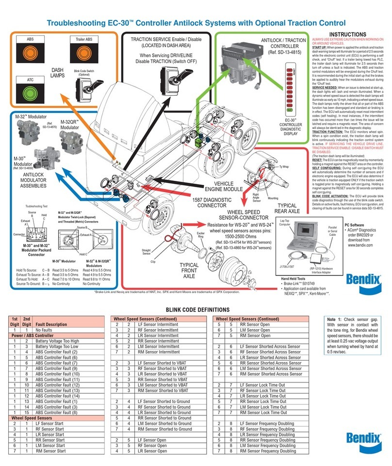
TROUBLESHOOTING
FaultinformationcanberetrievedfromtheEC-30™controller
byusing thediagnostic LEDdisplay, blinkcode diagnostics
ora diagnostic tool. However,the technician must confirm
whether the fault resides in the component, wiring or
connectors. The following troubleshooting flow charts will
assist the technician in isolating the cause of the fault.
Troubleshooting should alwaysbegin by observing the
ABS warning lamp and the ATC active/warning lamp
during the EC-30™controller power-up sequence.
Ifit is necessary tomake electrical measurements, always
begin by taking voltage and resistance measurements at
the30-pin and 18-pinwire harness connectors.
Oncethecircuitfaultisfound,isolate theareaneedingrepair
by repeating the measurements at all connections in the
affectedcircuit (modulator,wheel speed sensor, etc.).
Novoltage orresistance measurementsareto bemade on
thebulkhead connector pins of theEC-30™controller.
Whenrepairsaremade, reconnecttheelectricalconnectors
to the EC-30™controller and torque the connector
retaining jack-screws to 15-20 in. lbs. Over-tightening
the ECU connector jack-screw(s) can cause damage
to the EC-30™controller.
Troubleshooting Flowcharts
SectionA-Power-up sequence -ABS warning lamp and
ATC active/warning lamp
SectionB- Power-upsequence -Trailer ABSwarning lamp
Section C -ABS warning lamp
SectionD -ATCactive/warning lamp
Section E - TrailerABS warning lamp
Section F - Diagnostic LED quick reference
Section G - Power to the EC-30™controller
Section H - Wheel speed sensors
Section I - ABS modulators
SectionJ -ATCmodulator
Section K - Serial communication

20
SECTION A - EC-30™CONTROLLER POWER-UP SEQUENCE -
ABS WARNING LAMP AND ATC ACTIVE/WARNING LAMP
VerifythattheATCactive/warninglamp
turns off after 2.5 seconds. This lamp
may blink, displaying the ATC
configuration during power up. See
figure 7.
The ATC active/warning lamp should
immediately illuminate when ignition
poweris applied to the vehicle.
YES
NO
NO
YES
ATC Active/Warning Lamp at
Power-Up
Verify that the ATC enable/disable
switch is set to enable ATC. Turn
ignition on and observe ATC active/
warninglamp.
TheATCunitisfunctioning
normally. NoservicetoATC
componentsis needed.
ABS Warning Lamp at Power-Up
Verifythat theABSwarning lamp stays
on for 2.5 seconds and then turns off.
The ABS warning lamp should
immediately illuminate when ignition
poweris applied to the vehicle.
Turnignition on and observe the ABS
warninglamp.
YES
NO
NO
YES
The ABS unit is
functioning normally.
No service to ABS
componentsisneeded.
ABSwarning lamp
does not come on.
Go to Section C.
TheABS warninglamp
stays on.
Go to Section F.
TheATCactive/warning
lamp stays on.
Go to Section F.
ATCactive/warninglamp
does not come on.
Go to Section D.
Other manuals for EC-30 ABS-ATC CONTROLLER
1
Table of contents
Other BENDIX Controllers manuals

BENDIX
BENDIX ULTIMATE TOW Manual

BENDIX
BENDIX EC-13 TRAILER ANTILOCK CONTROL User manual

BENDIX
BENDIX EC-15 ANTILOCK CONTROLLER ASSY User manual

BENDIX
BENDIX EC-14 ANTILOCK CONTROLLER User manual

BENDIX
BENDIX EC-60 ABS-ATC ESP CONTROLLERS ADV User manual

BENDIX
BENDIX MC-30 TRAILER ABS CONTROLLER User manual

BENDIX
BENDIX BRAKE CHAMBERS User manual

BENDIX
BENDIX EC-17 ANTILOCK TRACTION CONTROL User manual

BENDIX
BENDIX EC-16 ANTILOCK CONTROLLER User manual

BENDIX
BENDIX EC-15 ANTILOCK CONTROLLER ASSY User manual