Installation
Instructions Bendix®EC-30™ECU
Replacement Kit
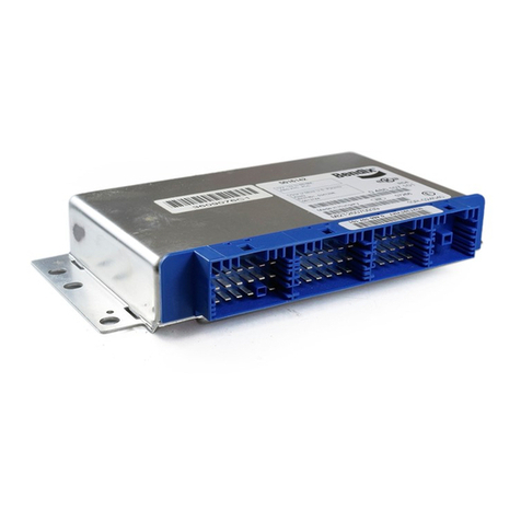
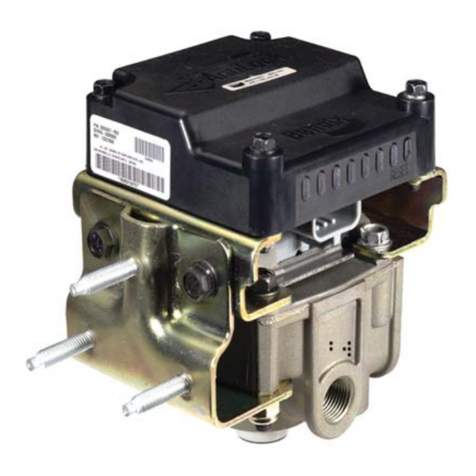
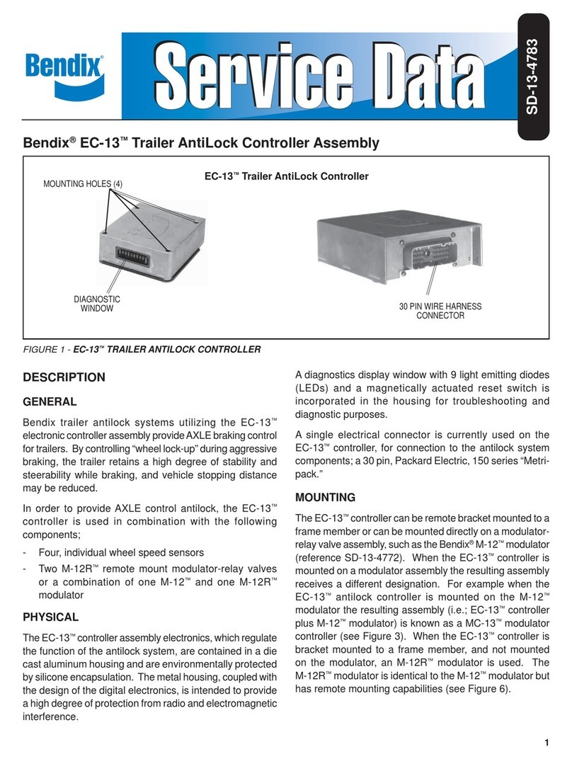
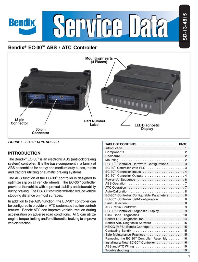
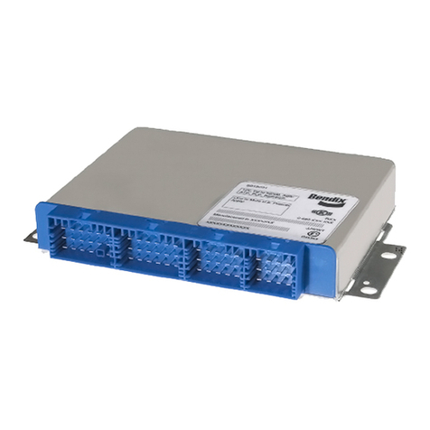
FIGURE 1 - BENDIX®EC-30™ECU, AND ACOM™DIAGNOSTICS SOFTWARE CD
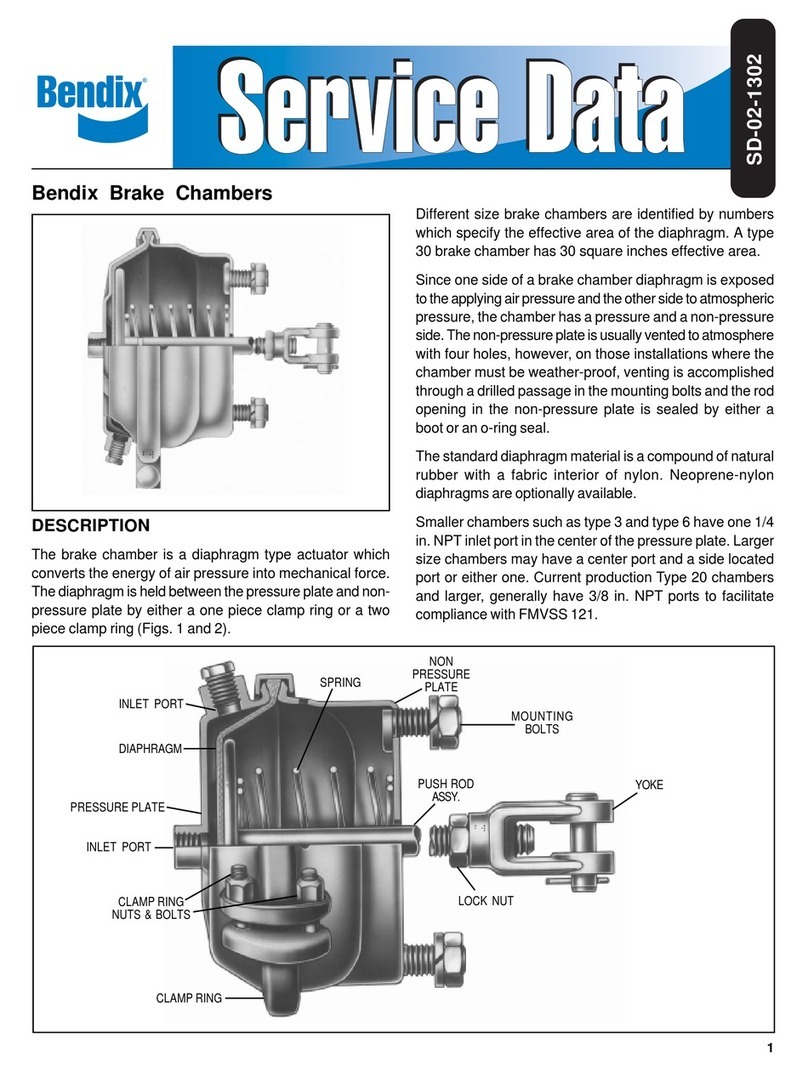
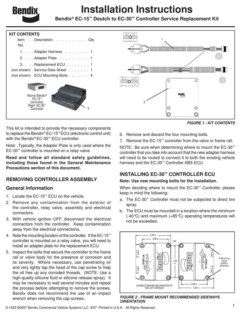
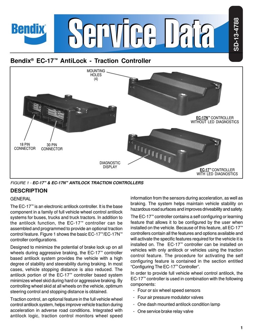
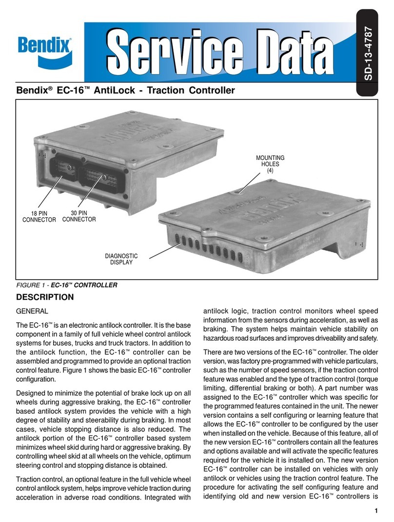
This kit is intended for the replacement of a Bendix®
EC-30™Electronic Control Unit (ECU). The following are the
necessary steps to replace and configure the replacement
ECU.
PREPARATION:
Follow all standard industry safety precautions,
including, but not limited to, those listed at the end of
this document. Park the vehicle on level ground, chock
wheels,andturnofftheignition. LocatetheBendix®EC-30™
Electronic Control Unit (ECU) on the vehicle.
1. Remove the wire harness connectors from the ECU.
2. Remove the four fasteners securing the ECU and retain
for re-installation. Dispose of ECU.
3. Install the replacement ECU and tighten the fasteners to
98 in-lbs.
4. Inspectthewireharnessesandconnectorsforcorrosion,
damage, etc. Replace as necessary. Insert the wire
harnessconnectorsintothereplacementECUandensure
that the harness is securely attached to the vehicle.
Torque the connector retaining screws to 15-20 in-lbs.
CONFIGURATION PROCESS - PART ONE
Replacement ECUs typically require a self-configuration
to adjust to the number of wheel speed sensors and/or the
AutomaticTraction Control(ATC)configurationofthe vehicle.
To Self-Configure:
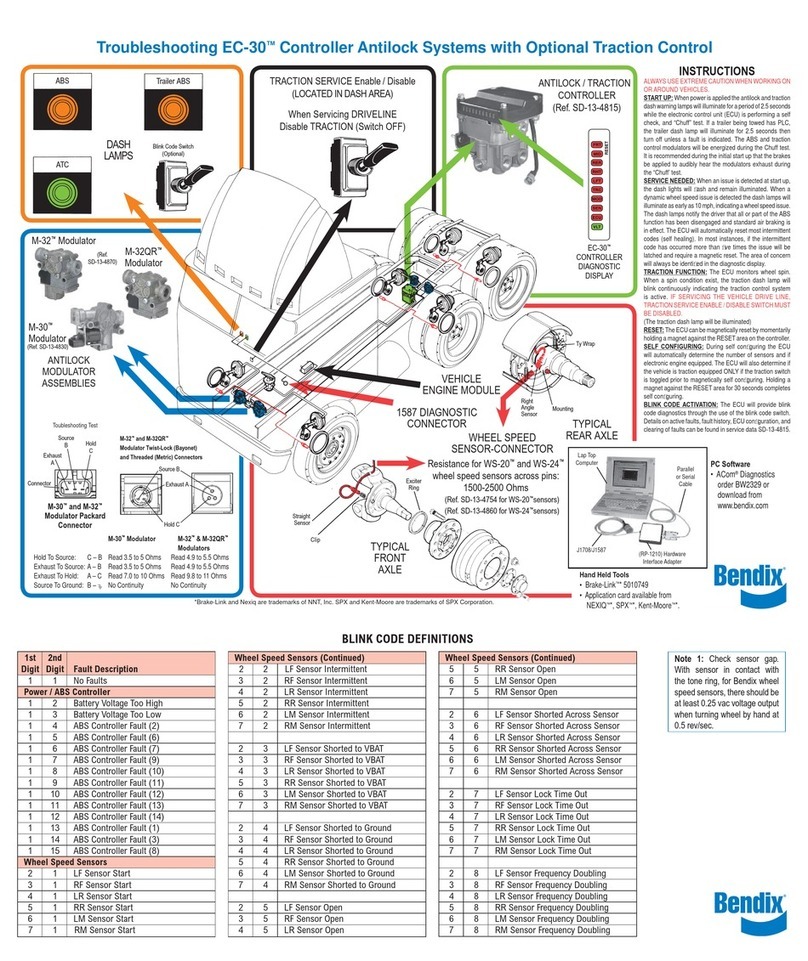
a. Verify that the following are connected to the EC-30™
ECU and are operational:
• All connectors to the ECU.
• J1939 or J1922 communication link to the engine.
• ATC active/indicator lamp.
• ATC enable/disable switch (NOTE: Switch must be
toggled prior to self-configuration if enabling ATC).
b. Self-Configuration Procedure
Verify that all ECU, communication, sensor, and ABS
modulator connectors are in place and then turn the ignition
poweron. ToggletheATC enable/disable switch ifequipped.
Activate an EC-30™controller self-configuration by one of
the following actions:
• Hold a magnet on the reset location of the Remote
DiagnosticUnit(RDU) for approximately 20 seconds (until
the LEDs begin to rapidly roll), then remove the magnet.
• Hold a magnet on the reset location of the diagnostic
displayfor more than 6seconds,but less than 11 seconds,
then remove the magnet to initiate a self-configuration.
• UsingACom™Diagnostic Software (version 5.9 or higher)
in the "configuration window" select the "self-config"
button or select "modify and configure the ECU" from the
parameters available in the "configuration window".
When the self-configuration process is complete, the EC-30™
controllerwillautomaticallygo throughthe power-upsequence
andshow thenewconfigurationon itsLEDdiagnostic display.
If the EC-30™controller was properly configured for wheel
speed sensors and ATC, both the ABS and ATC indicator
lamps will extinguish at the end of the power-up sequence.
CONFIGURATION PROCESS - PART TWO
Almost all Bendix replacement ECUs support Power Line
Carrier (PLC). Using ACom™Diagnostic Software (version
5.9or higher), confirmthatthe ECU installed hasthisfeature.
Some older vehicles, however, may not support PLC. In
these cases, it is recommended that the technician turn off
the ECU's support of PLC.
Bendix®EC-30™ECU
S-1516 © 2009 Bendix Commercial Vehicle Systems LLC 11/09 Printed in U.S.A. All Rights Reserved.
Use a magnet here to activate
the RESET switch
Bendix®ACom™
Diagnostic Software
BW2329 - available on
bendix.com to order or
download
