manuals.online logo
Brands
  1. Home
  2. •
  3. Brands
  4. •
  5. BENDIX
  6. •
  7. Controllers
  8. •
  9. BENDIX EC-15 ANTILOCK CONTROLLER ASSY User manual

BENDIX EC-15 ANTILOCK CONTROLLER ASSY User manual

1
S-1503 ©2007 Bendix Commercial Vehicle Systems LLC 8/07 Printed in U.S.A. All Rights Reserved.
Installation Instructions
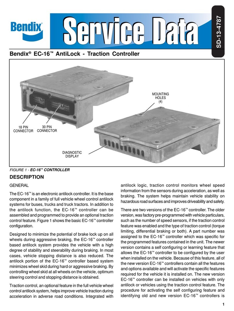
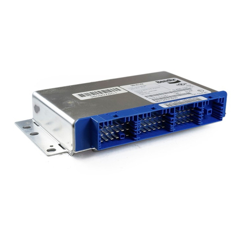
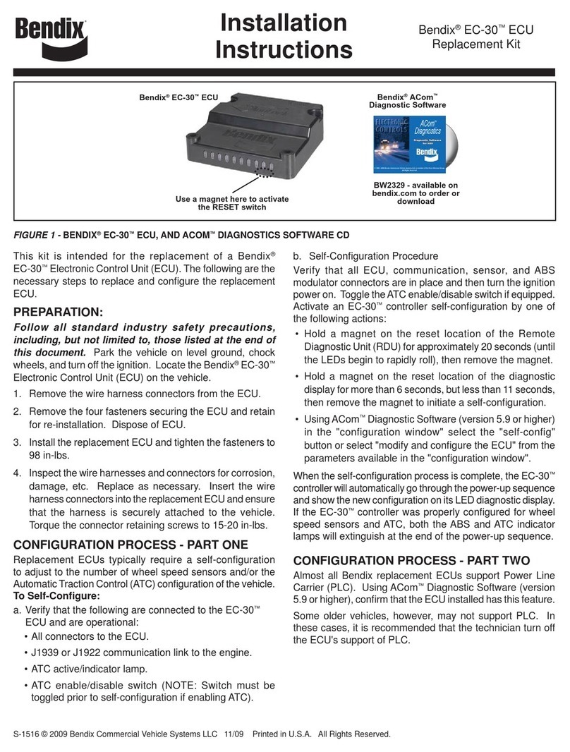
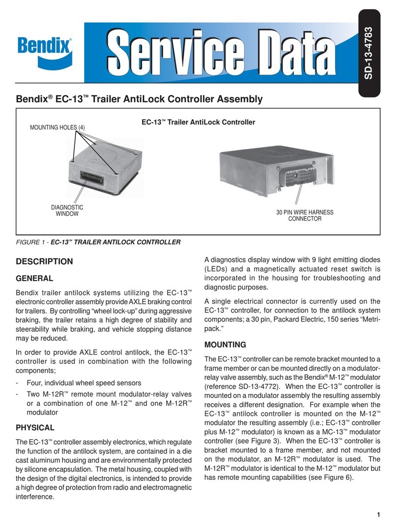
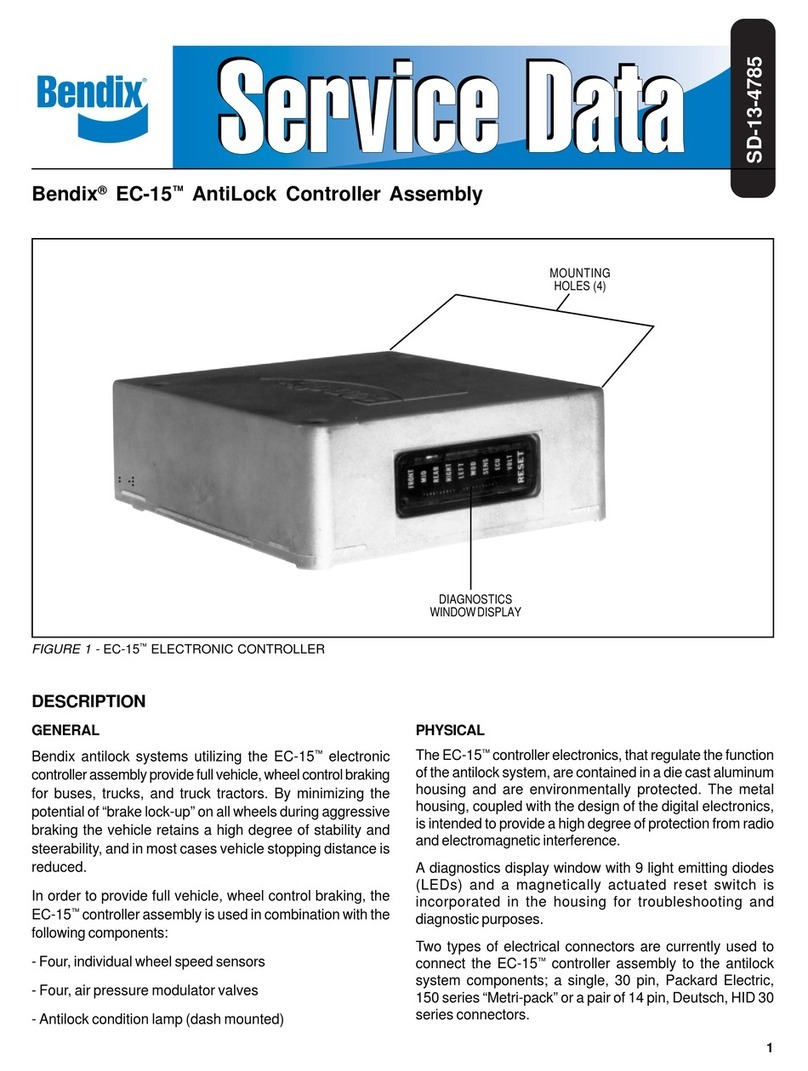
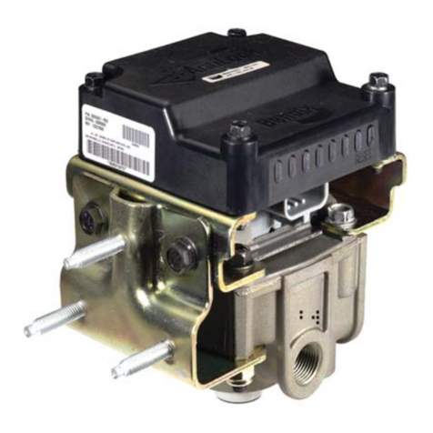
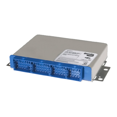
Bendix®EC-15™Deutch to EC-30™Controller Service Replacement Kit
This kit is intended to provide the necessary components
toreplacetheBendix®EC-15™ECU(electroniccontrolunit)
with the Bendix® EC-30™ECU controller.
Note: Typically, the Adapter Plate is only used where the
EC-30™controller is mounted on a relay valve.
Read and follow all standard safety guidelines,
including those found in the General Maintenance
Precautions section of this document.
REMOVING CONTROLLER ASSEMBLY
General Information
1. Locate the EC-15™ECU on the vehicle.
2. Remove any contamination from the exterior of
the controller, relay valve, assembly and electrical
connectors.
3. With vehicle ignition OFF, disconnect the electrical
connectors from the controller. Keep contamination
away from the electrical connections.
4. Notethemountinglocationofthecontroller. IftheEC-15™
controller is mounted on a relay valve, you will need to
install an adapter plate for the replacement ECU.
5. Inspect the bolts that secure the controller to the frame
rail or valve body for the presence of corrosion and
its severity. Where necessary, use penetrating oil
and very lightly tap the head of the cap screw to help
the oil free up any corroded threads. (NOTE: Use a
high-quality silicone fluid or silicone release spray). It
may be necessary to wait several minutes and repeat
the process before attempting to remove the screws.
Bendix does not recommend the use of an impact
wrench when removing the cap screws.
6. Remove and discard the four mounting bolts.
7. Remove the EC-15™controller from the valve or frame rail.
NOTE: Be sure when determining where to mount the EC-30™
controllerthatyoutakeintoaccount that the new adapter harness
will need to be routed to connect it to both the existing vehicle
harness and the EC-30™Controller ABS ECU.
INSTALLING EC-30™CONTROLLER ECU
Note: Use new mounting bolts for the installation.
When deciding where to mount the EC-30™Controller, please
keep in mind the following:
a. The EC-30™Controller must not be subjected to direct tire
spray.
b. The ECU must be mounted in a location where the minimum
(-40°C) and maximum (+85°C) operating temperatures will
not be exceeded.
FIGURE 1 - KIT CONTENTS
KIT CONTENTS
Item . . Description. . . . . . . . . . . Qty.
No.
1. . . . Adapter Harness . . . . . . . . 1
2. . . . Adapter Plate . . . . . . . . . . 1
3. . . . Replacement ECU . . . . . . . . 1
(not shown) Service Data Sheet . . . . . . . 1
(not shown) ECU Mounting Bolts . . . . . . . 4
1
2
3
Above:Bendix®
EC-15™
Controller,
Right:EC-30™
Controller
FIGURE 2 - FRAME MOUNT RECOMMENDED SIDEWAYS
ORIENTATION
4.90
in.
3.98in.
5.33in.
4Mounting
Holes
0.295in.
Diameter
3.98in.
5.33in.
CONNECTORSMAYBEORIENTEDTO
THELEFTORRIGHT
OR
2
c. Determine if the EC-30™controller will be mounted on a
relay valve or on the frame. In either case, be sure that
the harness will reach both the old harness and the ECU
without strain.
d. If the EC-30™controller is mounted on the frame, Bendix
strongly recommends that the orientation is parallel to the
frame (see Figure 2). Mark the mounting hole locations,
and drill the 4 mounting holes (0.295 in. diameter).
e. If the EC-30™controller is to be mounted on a relay valve,
theadapterplateincluded in this kit will be required. Mount
the EC-30™controller using Grade 5 stainless steel bolts;
the maximum torque permitted is 98 in-lbs.
8. Perform the system check-out as outlined on page 3 of
these instructions.
GENERAL MAINTENANCE PRECAUTIONS
WARNING! PLEASE READ AND FOLLOW THESE
INSTRUCTIONS TO AVOID PERSONAL INJURY OR
DEATH:
When working on or around a vehicle, the following general
precautions should be observed at all times.
1. Park the vehicle on a level surface, apply the parking
brakes, and always block the wheels. Always wear safety
glasses.
2. Stop the engine and remove ignition key when working
under or around the vehicle. When working in the engine
compartment, the engine should be shut off and the
ignition key should be removed. Where circumstances
require that the engine be in operation, EXTREME
CAUTION should be used to prevent personal injury
resulting from contact with moving, rotating, leaking,
heated or electrically charged components.
3. Do not attempt to install, remove, disassemble or
assemble a component until you have read and
thoroughly understand the recommended procedures.
Use only the proper tools and observe all precautions
pertaining to use of those tools.
4. If the work is being performed on the vehicle’s air brake
system, or any auxiliary pressurized air systems, make
certain to drain the air pressure from all reservoirs
before beginningANY work on the vehicle. If the vehicle
is equipped with an AD-IS®air dryer system or a dryer
reservoir module, be sure to drain the purge reservoir.
5. Following the vehicle manufacturer’s recommended
procedures, deactivate the electrical system in a
manner that safely removes all electrical power from the
vehicle.
6. Never exceed manufacturer’s recommended pressures.
7. Never connect or disconnect a hose or line containing
pressure; it may whip. Never remove a component or
plug unless you are certain all system pressure has been
depleted.
8. Useonly genuine Bendix®replacement parts, components
and kits. Replacement hardware, tubing, hose, fittings,
etc. must be of equivalent size, type and strength as
original equipment and be designed specifically for such
applications and systems.
9. Components with stripped threads or damaged parts
should be replaced rather than repaired. Do not attempt
repairsrequiring machining orwelding unless specifically
stated and approved by the vehicle and component
manufacturer.
10. Prior to returning the vehicle to service, make certain all
components and systems are restored to their proper
operating condition.
11. For vehicles with Antilock Traction Control (ATC), theATC
function must be disabled (ATC indicator lamp should
be ON) prior to performing any vehicle maintenance
where one or more wheels on a drive axle are lifted off
the ground and moving.
*If any of the questions were answered with a “No”, the
Antilock system should be review by a qualified individual.
Fortechnicalassistance,call the BendixTechnicalAssistance
Team at (800)-247-2725.
INSTALLING THE ADAPTER HARNESS
1. Connect the Deutch vehicle harness connectors into the
appropriate Deutch connectors of the adapter harness.
2. Besurethattheadapterharnesshasadequatestrainrelief
when installed so that it can be routed freely and is not
pulled tight.
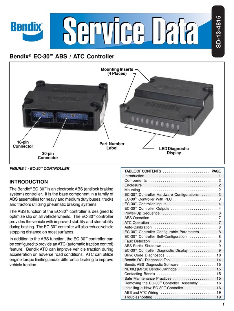
3. Install the 30- and 18-pin connectors to the EC-30™
controller ABS ECU, torquing the retaining cap screws to
15-20 in-lbs.
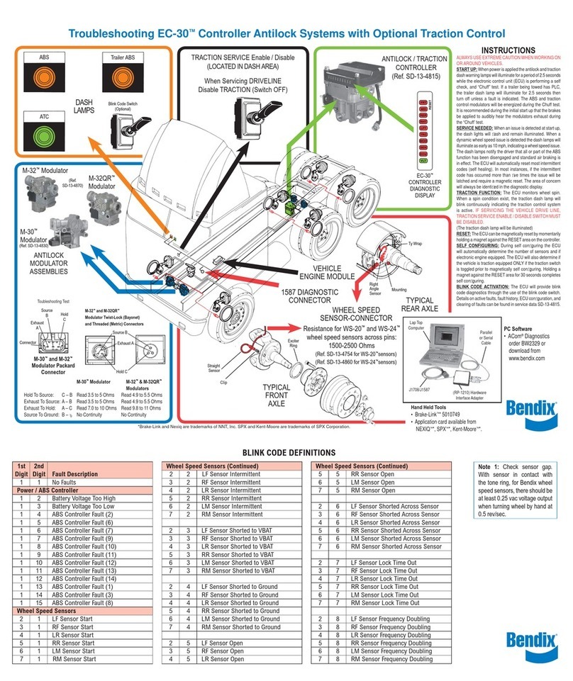
4. Apply ignition power and monitor the EC-30™Controller
power-up sequence and the LEDs on the ECU. Verify
that only a green VLT LED is illuminated, no red LEDs.
For all other Diagnostic Trouble Codes, including where
reconfiguration is needed, see the Service Data sheet in
this kit for full instructions.
5. EC-30™Controller Self-configuration Procedure.
Verifythat allECU,communication,sensor,ABSmodulator
andATC modulator connectors are in place and then turn
the ignition power on.
ActivateanEC-30™controller self-configuration byholding
a magnet on the "reset" location of the diagnostic display
for about 20 seconds (until the LEDs begin to rapidly roll)
then remove the magnet.
6. Use sealing plugs to cover any unused wire harness
terminals.
7. Checkthat all ECU connectors are completelyseated and
torqued correctly.
ECU Installation yes no*
Is the ECU mounted where it will not be
subjected to direct wheel spray or temperatures
of lower than -40° C or more than +85° C?
Is the ECU mounted in a location where
moisture can drain away from it?
Is the ECU (frame) mounted in a sideways
manner (see Figure 2)?
Are the ECU mounting bolts properly torqued
(maximum permitted is 98 in-lbs.)?
3
CONTACTING BENDIX
www.Bendix.com
The Bendix on-line troubleshooting guides help
you determine the cause of most performance
issues with the braking system. For additional
troubleshooting information please see the
Service Data sheet included in this kit.
The Bendix on-line contacts guide will make
it easy for you to find the Bendix contacts you
need. From this page, you can navigate to
technical support contacts, Service Engineers,
BendixAccount Managers,internationalcontacts
andmore. Bendix.com is your completeBendix
resource.
Bendix Technical Assistance Team
For direct personal technical support, call the
Bendixtechnical assistance team at 1-800-AIR-
BRAKE(1-800-247-2725-2-1),Mondaythrough
Friday, 8:00 A.M. to 6:00 P.M. EST, and follow
the instructions in the recorded message.
Or, you may e-mail the Bendix technical
assistance team at: [email protected].
To better serve you, please record the following
information before calling the Bendix Tech
Team:
Bendixproductmodel number,partnumber and
configuration.
Vehicle make and model.
Vehicle configuration. (Number of axles, tire
size, etc.)
System performance symptoms. When do they
occur?
What faults have been identified using blink
codes or diagnostic tools?
What troubleshooting / measurements have
been performed?
WhatBendixservice data literature do you have
or need?
S-1503 ©2007 Bendix Commercial Vehicle Systems LLC 8/07 Printed in U.S.A. All Rights Reserved.
*If any of the questions were answered with a “No”, the Antilock system
should be review by a qualified individual. For technical assistance,
call the Bendix Technical Assistance Team at 1-800-AIR-BRAKE,
(1-800-247-2725).
System Check-out yes no*
With the brake system fully charged with air, fully apply the
service brakes and hold. Remove and apply ignition power.
Does each PMV (modulator) exhaust air in the following
pattern (SA Right, SA Left, DA Right, and DA Left)?
Does each PMV exhaust air once per pattern (not twice)?
Does the pattern of PMV exhausts repeat?
Did the ABS indicator lamp illuminate for a period of
approximatelythreeseconds andthenextinguish? (Assuming
no diagnostic trouble codes are present.)
Verify that only the green LED is illuminated. Any red LEDs
that are illuminated indicate a diagnostic trouble code.
Withthepower off,remove the30pinconnectorfrom theECU.
Key vehicle on. Does the ABS indicator lamp illuminate?
DoestheABSindicatorlampilluminateasrequiredwhenABS
is disabled due to a fault in the system?
(Whereanoff-boarddiagnosticdeviceisavailablefortesting.)
Is the ECU communicating over the J1587 link? (The J1587
link may not be connected to the ABS ECU.)
Is the correct ECU installed? (Verify ECU part number)
Are all Wheel Speed Sensors (WSS) wired properly to the
ECU? (forexample,SALeft WSS to SALeft WSS ECU input)
Open each wheel speed sensor connection, making sure the
correct component and location are displayed on the LEDs:
Steer Axle Right Sensor
Steer Axle Left Sensor
Drive Axle Right Sensor
Drive Axle Left Sensor
Do all WSS have acceptable signal output (0.25 VAC @ 0.5
RPS)?
Are all PMVs wired properly to the ECU? (for example, SA
Left PMV REL to SA Left PMV REL ECU input)
Open each modulator connection making sure the correct
component and location are displayed on the LEDs:
Steer Axle Right Modulator
Steer Axle Left Modulator
Drive Axle Right Modulator
Drive Axle Left Modulator
If the vehicle is equipped with a retarder relay, is the ECU
configured to control the relay?
Does the ECU performABS properly on each wheel? Where
a test track or similar area is available, test drive the vehicle
and make sure ABS is operating correctly.

Other manuals for EC-15 ANTILOCK CONTROLLER ASSY

1

This manual suits for next models

1

Other BENDIX Controllers manuals

BENDIX EC-15 ANTILOCK CONTROLLER ASSY User manual

BENDIX

BENDIX EC-15 ANTILOCK CONTROLLER ASSY User manual

BENDIX EC-14 ANTILOCK CONTROLLER User manual

BENDIX

BENDIX EC-14 ANTILOCK CONTROLLER User manual

BENDIX EC-17 ANTILOCK TRACTION CONTROL User manual

BENDIX

BENDIX EC-17 ANTILOCK TRACTION CONTROL User manual

BENDIX EC-16 ANTILOCK CONTROLLER User manual

BENDIX

BENDIX EC-16 ANTILOCK CONTROLLER User manual

BENDIX ULTIMATE TOW Manual

BENDIX

BENDIX ULTIMATE TOW Manual

BENDIX EC-13 TRAILER ANTILOCK CONTROL User manual

BENDIX

BENDIX EC-13 TRAILER ANTILOCK CONTROL User manual

BENDIX EC-30 ECU User manual

BENDIX

BENDIX EC-30 ECU User manual

BENDIX EC-60 ABS-ATC ESP CONTROLLERS ADV Reference manual

BENDIX

BENDIX EC-60 ABS-ATC ESP CONTROLLERS ADV Reference manual

BENDIX MC-30 TRAILER ABS CONTROLLER User manual

BENDIX

BENDIX MC-30 TRAILER ABS CONTROLLER User manual

BENDIX EC-60 ABS Mounting instructions

BENDIX

BENDIX EC-60 ABS Mounting instructions

BENDIX BRAKE CHAMBERS User manual

BENDIX

BENDIX BRAKE CHAMBERS User manual

BENDIX EC-60 ABS-ATC ESP CONTROLLERS ADV User manual

BENDIX

BENDIX EC-60 ABS-ATC ESP CONTROLLERS ADV User manual

BENDIX EC-30 ABS-ATC CONTROLLER User manual

BENDIX

BENDIX EC-30 ABS-ATC CONTROLLER User manual

BENDIX EC-30 ABS-ATC CONTROLLER Operating instructions

BENDIX

BENDIX EC-30 ABS-ATC CONTROLLER Operating instructions

BENDIX DD-3-SD-3 SAFETY ACTUATORS User manual

BENDIX

BENDIX DD-3-SD-3 SAFETY ACTUATORS User manual

Popular Controllers manuals by other brands

ETC Unison Foundry installation guide

ETC

ETC Unison Foundry installation guide

Glentronics USC3 installation instructions

Glentronics

Glentronics USC3 installation instructions

EVSE RARON user manual

EVSE

EVSE RARON user manual

Kangjie JKA Service manual

Kangjie

Kangjie JKA Service manual

Epever TRIRON1206N user manual

Epever

Epever TRIRON1206N user manual

Watlow EZ-ZONE PM Express user manual

Watlow

Watlow EZ-ZONE PM Express user manual

Siemens BACnet owner's manual

Siemens

Siemens BACnet owner's manual

Autonics DPU Series manual

Autonics

Autonics DPU Series manual

Carel WB000S series quick start guide

Carel

Carel WB000S series quick start guide

Agilent Technologies TwisTorr 74 FS user manual

Agilent Technologies

Agilent Technologies TwisTorr 74 FS user manual

Sullair 02250160-842 instruction manual

Sullair

Sullair 02250160-842 instruction manual

Balmar Max Charge MC-624 Installation and operator's manual

Balmar

Balmar Max Charge MC-624 Installation and operator's manual

Zapi 4Q Operating and users manual

Zapi

Zapi 4Q Operating and users manual

Sony WX-C570 operating instructions

Sony

Sony WX-C570 operating instructions

elsner elektronik RF-MSG2-DST Technical specifications and installation instructions

elsner elektronik

elsner elektronik RF-MSG2-DST Technical specifications and installation instructions

HIMA HIMatrix F35 Safety manual

HIMA

HIMA HIMatrix F35 Safety manual

Tornatech HFD Installation and maintenance manual

Tornatech

Tornatech HFD Installation and maintenance manual

CombiSteel 7525 Series manual

CombiSteel

CombiSteel 7525 Series manual

manuals.online logo
manuals.online logoBrands
  • About & Mission
  • Contact us
  • Privacy Policy
  • Terms and Conditions

Copyright 2025 Manuals.Online. All Rights Reserved.