6
DATI TECNICI
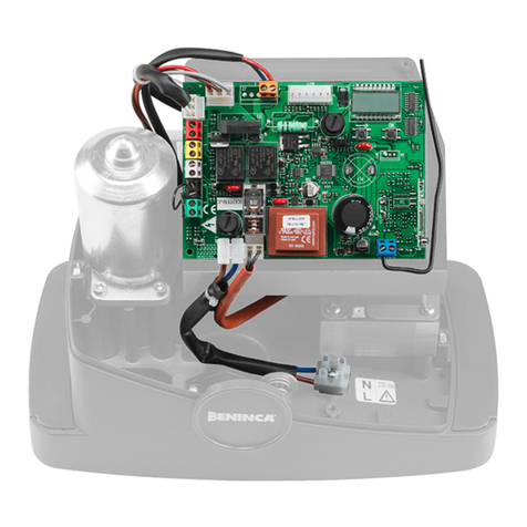
Alimentazione di rete 230 Vac 50/60 Hz
Uscita Motore 1 motore 230Vac monofase / 400Vac trifase
Potenza massima motore 230Vac monofase: 800 W
400Vac trifase: 2200 W
Uscita alimentazione accessori 24Vac 500mA max.
Grado di protezione IP54
Temp. funzionamento -20°C / +50°C
Ricevitore radio 433,92 MHz incorporato e confgurabile (ARC Advanced Rolling Code)
Connettore ad innesto per ricevente radio
N° codici memorizzabili 64
ITA AVVERTENZE
INFORMAZIONI GENERALI
E’ vietato l’utilizzo del prodotto per scopi o con modalità non previste nel presente manuale.
Usi non corretti possono essere causa di danni al prodotto e mettere in pericolo persone e cose.
Si declina ogni responsabilità dall’inosservanza della buona tecnica nella costruzione dei cancelli, nonché dalle deformazioni che potrebbero
verificarsi durante l’uso.
Conservare questo manuale per futuri utilizzi.
INFORMAZIONI PER L'INSTALLATORE
Questo manuale è destinato esclusivamente a personale qualificato per l’installazione e la manutenzione di aperture automatiche.
L’installazione deve essere effettuaua da personale qualificato (installatore professionale, secondo EN12635), nell’osservanza della Buona
Tecnica e delle norme vigenti.
Verificare che la struttura del cancello sia adatta ad essere automatizzata.
L’installatore deve fornire tutte le informazioni relative al funzionamento automatico, manuale e di emergenza dell’automazione, e consegnare
all’utilizzatore dell’impianto le istruzioni d’uso.
AVVERTENZE GENERALI
I materiali dell’imballaggio non devono essere lasciati alla portata dei bambini in quanto fonte di potenziale pericolo.
Non disperdere nell’ambiente i materiali di imballo, ma separare le varie tipologie (es. cartone, polistirolo) e smaltirle secondo le normative locali.
Non permettere ai bambini di giocare con i dispositivi di comando del prodotto.
Tenere i telecomandi lontano dai bambini.
Questo prodotto non è destinato a essere utilizzato da persone (bambini inclusi) con capacità fisiche, sensoriali o mentali ridotte, o con mancanza
di conoscenze adeguate, a meno che non siano sotto supervisione o abbiano ricevuto istruzioni d’uso da persone responsabili della loro sicurezza.
Applicare tutti i dispositivi di sicurezza (fotocellule, coste sensibili, ecc.) necessari a proteggere l’area da pericoli di impatto, schiacciamento,
convogliamento, cesoiamento.
Tenere in considerazione le normative e le direttive in vigore, i criteri della Buona Tecnica, l’utilizzo, l’ambiente di installazione, la logica di
funzionamento del sistema e le forze sviluppate dall’automazione.
L’installazione deve essere fatta utilizzando dispositivi di sicurezza e di comandi conformi alla EN12978 e EN12453.
Raccomandiamo di utilizzare accessori e parti di ricambio originali, utilizzando ricambi non originali il prodotto non sarà più coperto da garanzia.
Tutte le parti meccaniche ed elettroniche che compongono l'automazione soddisfano i requisiti e le norme in vigore e presentano marcatura CE.
SICUREZZA ELETTRICA
Prevedere sulla rete di alimentazione un interruttore/sezionatore onnipolare con distanza d’apertura dei contatti uguale o superiore a 3 mm.
Verificare che a monte dell’impianto elettrico vi sia un interruttore differenziale e una protezione di sovracorrente adeguati.
Alcune tipologie di installazione richiedono il collegamento dell’anta ad un impianto di messa a terra rispondente alle vigenti norme di sicurezza.
Durante gli interventi di installazione, manutenzione e riparazione, togliere l’alimentazione prima di accedere alle parti elettriche.
Scollegare anche eventuali batterie tampone se presenti.
L’installazione elettrica e la logica di funzionamento devono essere in accordo con le normative vigenti.
I conduttori alimentati con tensioni diverse, devono essere fisicamente separati, oppure devono essere adeguatamente isolati con isolamento
supplementare di almeno 1 mm.
I conduttori devono essere vincolati da un fissaggio supplementare in prossimità dei morsetti.
Ricontrollare tutti i collegamenti fatti prima di dare tensione. Gli ingressi N.C. non utilizzati devono essere ponticellati.
SMALTIMENTO
Come indicato dal simbolo a lato, è vietato gettare questo prodotto nei rifiuti domestici in quanto alcune parti che lo compongono potrebbero
risultare nocive per l’ambiente e la salute umana, se smaltite scorrettamente.
L’apparecchiatura, pertanto, dovrà essere consegnata in adeguati centri di raccolta differenziata, oppure riconsegnata al rivenditore al momento
dell’acquisto di una nuova apparecchiatura equivalente.
Lo smaltimento abusivo del prodotto da parte dell’utente comporta l’applicazione delle sanzioni amministrative previste dalla normativa vigente.
Le descrizioni e le illustrazioni presenti in questo manuale non sono impegnative.
Lasciando inalterate le caratteristiche essenziali del prodotto il fabbricante si riserva il diritto di apportare qualsiasi modifica di carattere tecnico, costruttivo
o commerciale senza impegnarsi ad aggiornare la presente pubblicazione.
