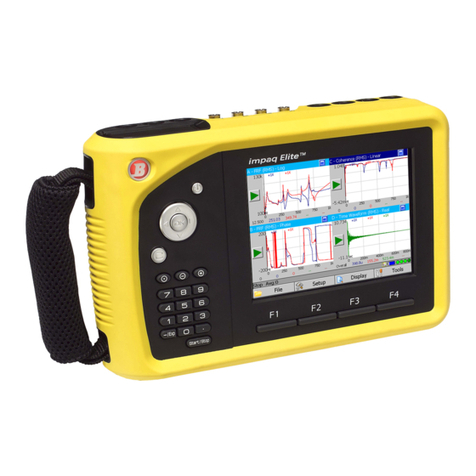
Benstone Fieldpaq II User manual

FieldpaqⅡ
ⅡⅡ
Ⅱ
Dynamic
Signal
Analyzer
User
Manual
Edition: December, 2013
B
ens
t
one
I
ns
t
rumen
t
s
, I
nc
.
-
32905
Nor
t
hland
Cour
t
-
St. P
aul
,
MN
55045
T
elephone
:
651-257-6500
www
.
bens
t
one
.
com
Copyrigh
t ©
2005
,
6
all
righ
t
s
reserved

2
Con
t
en
t
s
1
WELCOME
.............................................................................................................................
4
1.1
S
YSTEM
C
ONTENTS
..................................................................................................
4
1.2
Q
UALITY
C
ONTROL
-
C
ALIBRATION
............................................................................
4
1.3
U
SING
T
HIS
M
ANUAL
.....................................................................................................
4
1.4
H
ELP
................................................................................................................................
5
2
INTRODUCTION
....................................................................................................................
6
2.1
L
AYOUT OF THE
FIELDPAQ
Ⅱ
ⅡⅡ
Ⅱ
.......................................................................................
6
2.2
MAIN KEYPAD
................................................................................................................
7
2.3
FUNCTION KEYPAD
.......................................................................................................
8
2.4
C
ONNECTORS
................................................................................................................
8
2.5
T
URNING
O
N
.................................................................................................................
9
2.6
C
HARGING THE BATTERY
..........................................................................................
10
2.7
S
PECIFICATION
............................................................................................................
11
3
UTILITY
PROGRAM.........................................................................................................
12
3.1
S
YSTEM
M
ENU
............................................................................................................
12
3.2
O
PTION
M
ENU
..............................................................................................................
13
3.3
P
ROGRAM
L
IST
...........................................................................................................
13
4
FFT
PROGRAM
...................................................................................................................
15
4.1
R
UN
FFT
PROGRAM
.....................................................................................................
15
4.2
N
AVIGATING THE DISPLAYS
.......................................................................................
15
4.3
S
OFT KEY MENU
:
F
ILE
...............................................................................................
17
4.4
S
OFT KEY MENU
:
S
ETUP
...........................................................................................
20
4.5
M
ODE MENU
..............................................................................................................
20
4.6
M
EASUREMENT
M
ENU
..............................................................................................
21
4.7
CHANNEL MENU :
S
ETTING UP THE PARAMETERS OF INPUT CHANNELS
..........
24
4.8
E
NGINEERING
U
NIT
M
ENU
:
S
ETTING UP THE
E
NGINEERING
U
NITS
....................
27
4.9
E
NVELOPE SETUP
....................................................................................................
31
4.10
S
OFT
K
EY
M
ENU
:
D
ISPLAY
.......................................................................................
34
4.11
T
RACE
S
ETUP
.............................................................................................................
39
4.12
S
ELECTING A FUNCTION FROM
T
RACE
S
ETUP MENU
...........................................
39
4.13
S
ELECTING THE TYPE OF
Y
AXIS FROM
T
RACE
S
ETUP MENU
.............................
42
4.14
S
ETTING UP DATA TRACES DISPLAYED IN THE DATA WINDOW
...........................
43
4.15
S
OFT KEY MENU
:
T
OOLS
.........................................................................................
44
4.16
S
TATUS
B
AR
................................................................................................................ 51
4.17
W
ATERFALL
M
EASUREMENT
..................................................................................... 52
4.18 STEP CONTROL OF WATERFALL MEASUREMENTS .............................................. 52

3
4.19
N
AVIGATING THE
D
ISPLAY OF
W
ATERFALL
P
LOT
.............................
53
4.20
E
NVELOPE
S
CANNING
.............................................................................................
56
4.21
T
OOLS
...........................................................................................................................
57
5
BALANCER
PROGRAM
.......................................................................................................
58
5.1
R
UN
B
ALANCER PROGRAM
.......................................................................................
58
5.2
M
AIN
D
ISPLAY
.............................................................................................................
58
5.3
E
XIT
...............................................................................................................................
59
5.4
P
REFERENCE
............................................................................................................... 61
5.5 TOOLS .......................................................................................................................... 61
5.6 BALANCING ................................................................................................................. 61
5.7
S
INGLE
P
LANE
.............................................................................................................
62
5.8
D
UAL
P
LANE
................................................................................................................
67
5.9
O
VERHUNG
..................................................................................................................
67
5.10
3
B
ALANCERS
–
S
INGLE
P
LANE
................................................................................
68
5.11
3
B
ALANCERS
–
D
UAL
P
LANE
................................................................................... 70
5.12 CONTINUE A SAVED JOB .......................................................................................... 72
5.13 REDO A SAVED JOB ................................................................................................... 73
5.14 BALANCERS Mass ...................................................................................................... 77

4
1 Welcome
Pl
ease
Rea
d
Bef
o
re
P
r
o
cee
ding
THE BATTERY IS NOT CHARGED WHEN YOU TAKE IT OUT OF THE BOX.
DO NOT REMOVE THE BATTERY PACK WHEN THE DEVICE IS CHARGING.
YOUR WARRANTY IS INVALIDATED IF YOU OPEN OR TAMPER WITH THE
DEVICE’S OUTER CASING.
Congratulations on your purchase of the Fieldpaq
Ⅱ
Dynamic Signal Analyzer. This
instrument is built with pride and has features that you will find useful in your
measurements. This manual will provide you with all the information you require to
get the greatest benefit from your measurement system.
Engineers, technicians and maintenance personnel will find that the Fieldpaq
Ⅱ
is
intuitive, has an easy-to-use keypad and touch screen, and is invaluable for
advance sound and vibration measurements.
The Benstone Instruments Dynamic Signal Analyzer is very flexible. Your system
may have come with only one software feature, but the Fieldpaq
Ⅱ
is designed for
easy upgrade of software features as needed by the user.
1.1 System Contents
Your system includes this manual, the analyzer, battery charger, Lithium-ion
battery, a SD card, USB cable, a hard carrying case, an utility program CD and
other optional accessories (if any).
1
.
2
Qu
a
li
ty
C
on
tr
ol
-
Ca
lib
rat
ion
Your system has been calibrated to the highest standards. The Fieldpaq
Ⅱ
has
gone through a series of testing including a 72 hours burn-in period, and has
passed CE Certification and is rated at IP 65 for splash and harsh environments.
1
.
3
Us
ing Thi
s
Ma
nu
a
l
In this manual you will find information for using the various features of the
Fieldpaq
Ⅱ
. Once you become familiar with the system, you will only need to
refer occasionally to this manual for specifications or to certain aspects of
operation.

5
1
.
4 He
lp
Benstone Instruments wants to help you get the most from your system. If there
is anything else we can do, please feel free to call or Email us.
Telephone : 651-257-6500
Fax : 651-357-4004
S
ervice
or
Calibra
t
ion
:
suppor
t
@bens
t
one
.
com
G
eneral
in
f
orma
t
ion
:
in
f
o@bens
t
one
.
com
O
r
you
can
visi
t
our
websi
t
e
a
t :
www
.
bens
t
one
.
com
The website is the first place to look for product updates, application notes, or
technical tips.

6
2 Introduction
This chapter gives a general introduction to the Fieldpaq
Ⅱ
. It provides an overview
of the layout, keypad, connectors and other hard ware features. Detail of the
individual operation of each function will be described in later chapters
2
.
1
L
ay
ou
t
o
f
t
h
e
FieldpaqⅡ
ⅡⅡ
Ⅱ
ò
St
orage
card
and
U
SB
1
.
1
connec
t
or
ò
Connec
t
ors
ò
Color
TFT t
ouch
screen
ò
F
old-able
s
t
and
ò
Main
keypad
ò
F
unc
t
ion
keypad
ò
Logo
and
power
indica
t
or
ò
B
a
tt
ery
compar
t
men
t &
cover
Shou
l
d
e
r
s
t
r
a
p
H
a
nd
s
t
r
a
p

7
2
.
2
ma
in
key
p
a
d
ò
Naviga
t
ion
keys
–
Use
t
hese
keys
t
o
move
a
f
ocus or
a
cursor
in
t
he
f
ollowing
occasions
:
¢
Move
a
cursor
t
o
le
ft
or
righ
t
¢
Move
t
he
f
ocus
in
a
lis
t
o
f
op
t
ions
¢
S
elec
t
an
ac
t
ive
window
ò
Cancel
K
ey
–
Use
t
his
key
f
or
t
he
f
ollowing
opera
t
ions
:
¢ Escape or abort from a menu
¢ Backspace when entering a string
ò
OK
key
–
Use
t
his
key
f
or
t
he
f
ollowing
opera
t
ions
:
¢
E
n
t
er
or
con
f
irm
a
selec
t
ion
¢
Call
ou
t t
he
t
race
se
t
up
menu
ò
St
ar
t/St
op
key
–
Use
t
his
key
t
o
s
t
ar
t
or
s
t
op
a measuremen
t.
ò
O
n
/
o
ff
key
–
use
t
his
key
t
o
t
urn
t
he
ins
t
rumen
t
on or
o
ff.
ò
P
lus
key
–
Z
oom
in
or
user
de
f
ine
ò
Minus
key
–
Z
oom
ou
t
or
user
de
f
ine
ò
Do
t
key
–
Change
t
ype
o
f
cursor
or
user
de
f
ine

8
2
.
3
f
un
ct
ion
key
p
a
d
There are 4 function keys underneath the LCD screen. The function of each
key is defined by the corresponding menu at the bottom of the LCD screen.
Note : Most of the functions can be accessed by both the keypad and by
clicking on the touch screen with your fingers. You may find that the keypad is
easier, or prefer using the touch screen display. Either way, you can choose
the method that best fits your needs.
2
.
4 C
onn
ect
o
rs
O
n
t
op
o
f t
he
Fieldpaq
Ⅱ
is
a
series
o
f
connec
t
ors
t
o
provide
an
in
t
er
f
ace
t
o
accep
t
ex
t
ernal
signals
(usually
f
rom
your
sensors)
,
power
supply
or
t
o
ou
t
pu
t
communica
t
ions
wi
t
h
ex
t
ernal
devices
like
a
compu
t
er
.
DC
DC
power
supply
AUX
Tacho
input,
TTL
output
and
RS-232C
interface
234
Triaxial
input
connector,
connecting
to
channel
2,3
and
4
Channel 1
Channel 2
(BNC
input
connectors)

9
2
.
5
Tu
r
ning On
P
ress
and
hold
t
he
on
/
o
ff
key
t
o
t
urn
on
your Fieldpaq
Ⅱ
. It t
akes
several
seconds
t
o
load
t
he
opera
t
ional
sys
t
em
,
and
t
hen
t
he
ins
t
rumen
t
will
show
you
t
he
main
display
as
f
ollows
.
Your display will show the icons of programs installed. You may only have
one program, or may have several programs depending on what was
purchased. At the lower right corner, you can see the clock and the battery
power gage.
To run a program, move the focus to the program icon with navigation keys,
and press OK key to run it. You can also run a program by double tapping the
icon with your finger.
Double
t
ap
t
he
icon
t
o
run
a program

10
P
o
w
e
r
2
.
6 C
h
ar
ging
t
h
e
b
attery
The Fieldpaq
Ⅱ
is designed to run continuously up to 6 hours with a fully
charged battery. When you turn on your
Fieldpaq
Ⅱ
, you can see the condition
of the battery power gage at the lower right corner of the screen.
To charge your Fieldpaq
Ⅱ
, plug the connector of power supply to the DC
connector of Fieldpaq
Ⅱ
. The power supply unit accepts 100 ~ 200 V AC
power. During the charging process, if you turn on the instrument, you’ll see
that the battery power gage scrolling in red color. It is normal that the casing
of the instrument gets a little bit warm during charging.
100
~
200
V
ac
You can also charge the battery or a backup battery via an optional charging
station. You can extend the operational hour in the field by replacing the
battery with a backup one.
O
p
t
ional
charging
s
t
a
t
ion
and
backup
ba
tt
ery
.
Ha
ndl
e
b
attery
p
acks
caref
ull
y
This product contains a Li-ion battery. There is a risk of fire and burns if the battery
pack is handled improperly. Do not attempt to open or service the battery pack. Do
not disassemble, crush, puncture, short external contacts or circuits, dispose of in
fire or water, or expose a battery pack to temperatures higher than 60˚C (140˚F).
Power
Supply

11
2
.
7
Sp
ec
i
f
i
cat
ion
O
pera
t
ing
S
ys
t
em
W
indows
C
E
Number
o
f I
npu
t
Channels
2+2 analog channels and 1 aux channel
Connec
t
or
St
yle
B
NC
on
2 I
npu
t
Channels
,
6
pin
Lemo
on
A
uxiliary
Channel
,
3
pin
L
E
M
O
power
supply
and
4
pin L
E
M
O t
riaxial
inpu
t
Channel
Coupling
A
C
,
DC
, IEPE
A
uxiliary
Channel
TT
L
I
n
,
(
f
rom
ex
t
ernal
t
rigger)
, TT
L
O
u
t
D
SP P
rocessor
T
exas
I
ns
t
rumen
t
s
TI TMS
320C6713B
E
x
t
ernal
Memory
SDHC Card
Card
(up
t
o
16 GB
memory)
B
a
tt
ery
Li-Po
7.
4
V
5400
m
A/
hr
,
Rechargeable
P
C
I
n
t
er
f
ace
U
SB
1
.
1
Mini
B t
ype
U
SB
Connec
t
or
LCD
Display
480X800
color
TFT
Display
, 5 inch t
ouch
screen
O
pera
t
ing
T
emp
-10
degrees
C
t
o
50
degrees
C
S
a
f
e
t
y
Cer
t
i
f
ica
t
ions
C
E
S
ealing
IP
65
(dus
t
and
splash
proo
f
)
Housing
ma
t
erial
ABS
and
TP
R
,
dual
ma
t
erial
injec
t
ion
W
eigh
t
2.8 lbs
,
(1.3
kg)
S
ize
9.6
in
x
5.2
in
x
2.5
in
(245
x
132
x
63
mm)
I
npu
t S
ignal Range
±
20
vol
t
s
Maximum
Dynamic
Range
>13
0
d
B (measured from spectrum with input pins shorted)
Input impedance 1M Ohm
F
requency
Range
0
Hz
t
o
40
kHz

12
3 Utility Program
Run the utility program from the main display of Fieldpaq
Ⅱ
. This program
allows you to review the system information, programs installed on this
instrument and setting up the system parameters. Use “cancel” key to leave
program.
I
n
t
he
U
t
ili
t
y
so
ft
ware
, t
here
are
t
hree
main
menus
: S
ystem Me
nu, Op
t
ion
Me
nu
and
P
r
og
ram
Li
st
.
3
.
1
S
ystem
Me
nu
T
he
sys
t
em
menu
displays
in
f
orma
t
ion
abou
t t
he
in
t
ernal
componen
t
s
o
f
your
Fieldpaq
Ⅱ
.

13
3
.
2
Op
t
ion
Me
nu
Using
t
he
[
Nav
ig
at
ion
Key
p
a
d]
and
pressing
[O
K
]
will
allow
t
he
user
t
o
selec
t
t
he
various
se
tt
ings
in
t
his
menu
,
such
as
da
t
e
/t
ime
,
Language
,
sound
on
or
o
ff,
backligh
t
power
managemen
t
and
calibra
t
ion
o
f t
he
t
ouch
screen
panel
t
o
t
he
ins
t
rumen
t.
3
.
3
P
r
og
ram
Li
st
T
his
display
will
show
a
lis
t
o
f
programs
curren
t
ly
ins
t
alled and
ac
t
ive
on
your
Fieldpaq
Ⅱ
.
T
he
Fieldpaq
Ⅱ
has
a
buil
t
-in
t
ime
lock
f
or
cer
t
ain
programs
. If
you
have
a demo
version
o
f
a
par
t
icular
so
ft
ware
, t
he
t
ime
lock
will
display
how
much remaining
t
ime
is
le
ft. If
you
need
t
o
ge
t
a
demo
program
f
or
evalua
t
ion
,
please
con
t
ac
t
B
ens
t
one
I
ns
t
rumen
t
s
f
or
help
.

14
T
o
ins
t
all
a
new
program
or
a
demo
program
,
you’ll
have
t
o
ge
t
a
key
code
f
rom
B
ens
t
one
I
ns
t
rumen
t
s
f
irs
t. T
hen
you
can
t
ap
t
he
“
I
ns
t
all”
bu
tt
on
t
o
conduc
t t
he
ins
t
alla
t
ion
which
will
guide
you
t
hrough
t
he
ins
t
all
process
.

15
4 FFT Program
4
.
1 R
un FFT p
r
og
ram
Move
t
he
f
ocus
t
o
highligh
t t
he
FFT
so
ft
ware
program
,
and
t
hen
press
[O
K]
t
o
run
t
his
program
. O
r
double
t
ap
t
he
program
icon
wi
t
h
your
f
inger
t
o
run
t
his
program
.
4
.
2
Nav
ig
at
ing
t
h
e
di
s
pl
ays
T
h
e mai
n
d
i
sp
la
y (b
el
ow)
shows
t
h
e mea
sur
e
d
d
ata i
n
up to two
w
i
ndows,
i
.
e
.,
P
a
n
e
A and P
a
n
e B
r
e
sp
ecti
v
el
y. You
ma
y
s
elect
on
e
of
t
h
e
s
e
d
ata
w
i
ndows
a
s
“acti
v
e”
wh
ile t
h
e
o
t
h
e
r
w
i
ndow
i
s
“i
n
acti
v
e”. T
h
e acti
v
e
w
i
ndow
h
a
s
a
d
ee
p
b
l
u
e title
b
a
r,
wh
ile t
h
e “i
n
acti
v
e”
w
i
ndow
h
a
s
a li
gh
t
b
l
u
e title
b
a
r.
T
h
is
w
i
ndo
w
is
“
a
c
t
i
v
e
,
”
be
c
au
s
e
t
h
e
t
i
t
l
e
ba
r
is
in
d
e
e
p
b
l
u
e
c
o
l
o
r
.
P
l
o
t a
r
ea
P
l
o
t a
r
ea
Y
s
cale la
b
el
T
r
ace
S
et
up
Title
bar
X
s
cale la
b
el
Cursor
la
b
el
Status
bar
Soft
keys

16
Selecting an active window
To select an active window, you can either use the keypads to select, or select
by tapping the desired window directly.
Using the Keypads
Press Cancel key to make the title bar of the active window turn red. And then
use the navigation keys to move the red focus to the desired window. Press
[
OK
] to confirm your selection.
Use Touch Screen
Tapping in a different window will make this area active.
M
ax
i
m
ize
o
r
R
e
sto
re
an
A
c
t
i
v
e
W
i
ndow
The user can tap the title bar of an active window to maximize it or restore it.

17
4.3
So
ft
key
me
nu
:
Fil
e
F
ile
Managemen
t
allows
you
t
o
properly
naviga
t
e
t
he
sys
t
em
t
o
save
,
rename
,
and
load
f
iles
. T
ap
t
he
f
ile
bu
tt
on
on
t
he
screen
or
press
F
1
key
t
o
open
t
he
f
ile
menu
. P
ress
[
cancel
]
key
or
t
ap
t
he
f
ile
bu
tt
on
again
t
o
close
t
he
window
.
Exit :
Exits this program.
About :
Displays the software and firmware version.
Filename Options :
When you save a data file, the system will automatically
assign a filename for it. You can choose the optional items for generating a
default filename.

18
File Manager :
The file manager is an utility to cut, copy, paste, delete new
folder, or rename.
File Manager-Edit menu :
Pressing “Select All” will select all files in the
directory or “Unselect” will unselect all files selected. After you have selected
the files, you can cut, copy, paste, or delete the files into another directory if
desired.
Note : You can always remove the memory card from the Fieldpaq
Ⅱ
and then
perform these functions from your PC.
Fil
e
Ma
n
a
g
er-
Vi
e
w
Me
nu
:
S
elec
t
ing
V
iew
allows
you
t
o
arrange
t
he
icons by
Name
, T
y
p
e
, Si
ze
,
or
Date
.
Op
e
n S
et
up : S
elec
t
ing
O
pen
S
e
t
up
t
o
open
a
se
t
up
f
ile
.f
s2
and
apply
i
t
s
se
t
up
parame
t
ers
t
o
t
he
FFT
program
.
S
ave
t
o
Defa
ul
t :
S
aves
t
he curren
t
se
t
up parame
t
ers
t
o
t
he
de
f
aul
t f
ile
D
EFA
UL
T.FS
2
.
Nex
t t
ime
you
access
t
he
FFT
program
,
i
t
will
s
t
ar
t
up
wi
t
h
t
he
de
f
aul
t
se
t
up
.

19
Save Setup :
Selecting Save Setup opens up a new window for saving the
setup parameters into a file (.fs2). You can save the setup, rename the file
name, or create a new directory as shown in the previous pages.
Open Data :
Selecting Open Data to open a saved data file as well as the
associated setup parameters.
S
ave
Data :
S
elec
t
ing
S
ave
Da
t
a
t
o
save
t
he
measured
da
t
a
as
well
as
t
he
associa
t
ed
se
t
up
parame
t
ers
t
o
a
da
t
a
f
ile
(
.f
d2)
. T
he
program
will
assign
a
f
ile
name
which
is
de
f
ined
in
t
he
f
ilename
op
t
ion
menu
. Y
ou
can
press
[OK]
bu
tt
on
or
t
ap
on
t
he
f
ile
name
t
o
edi
t t
he
f
ile
name
.
Save Layout : Selecting Save Layout to save the current display format into a
file (.flo). You can reload the saved display format from Display menu for quick
switching to a common used display.
Screen Capture : Selecting Screen Capture to save the display screen to an
image file (.jpg)

20
4
.
4
So
ft
key
me
nu
:
S
et
up
The Setup menu has five submenus : Mode, Measurement setup, Channel
setup, Engineering unit and Envelope. Each will be described in detail in the
following sections.
To enter a submenu, use the navigation keys to move right or left, and then
press [OK] to enter the menu. Or tap the menu label on the screen to enter.
To leave a menu, you can press Cancel to leave without saving the change,
or press the soft key Return to save the change and leave.
Local Soft keys :
Return : return to the submenu selection
Save to Default : save the current setup parameters to the default.fs2 file.
Load Default : Load the setup parameters from the default file (.fs2).
4.5 Mode menu
Selecting single block, power spectrum waterfall or Envelope
Singl
e
B
lo
ck :
T
he
program
o
ff
ers
all
t
he
available
f
unc
t
ions
,
like
t
ime
wave
f
orm
,
complex
spec
t
rum
,
au
t
o
power
spec
t
rum
,
e
t
c
. It
shows
only
one
single
block
o
f
da
t
a
a
t
a
t
ime
.
W
aterfa
ll
m
od
e :
T
he
program
per
f
orms
con
t
inuous
analysis
o
f
au
t
o
power
spec
t
rum
and
shows
t
he
da
t
a
in
a
wa
t
er
f
all
plo
t. I
n
wa
t
er
f
all
mode
you
can
selec
t
“armed
by
rpm”
or
“armed
by
t
ime
s
t
ep”
f
or con
t
rolling
t
he
progress
o
f
measuremen
t.
Table of contents
Other Benstone Measuring Instrument manuals
