Bently Nevada 3300/01 Series User manual

-~
ARTISAN
®
~I
TECHNOLOGY
GROUP
Your definitive source
for
quality
pre-owned
equipment.
Artisan Technology
Group
Full-service,
independent
repair
center
with
experienced
engineers
and
technicians
on staff.
We
buy
your
excess,
underutilized,
and
idle
equipment
along
with
credit
for
buybacks
and
trade-ins
.
Custom
engineering
so
your
equipment
works
exactly as
you
specify.
•
Critical
and
expedited
services
•
Leasing
/
Rentals/
Demos
• In
stock/
Ready-to-ship
•
!TAR-certified
secure
asset
solutions
Expert
team
ITrust
guarantee
I
100%
satisfaction
All
tr
ademarks,
br
a
nd
names, a
nd
br
a
nd
s a
pp
earing here
in
are
th
e property of
th
e
ir
r
es
pecti
ve
ow
ner
s.
Find the GE / Bently Nevada 3300/01-01 at our website: Click HERE

3300/01
SYSTEM
MONITOR
OPERATION MANUAL
BENTLY re\
NEVADA
•
PART NO. 80175-01

System Monitor
NOTICE
80175-01
READ THE FOLLOWING BEFORE INSTALLING OR OPERATING EQUIPMENT
Bently Nevada Corporation has attempted to identify areas of risk created by improper installation
and/or operation of this product. These areas of information are noted as WARNING or CAUTION
for your protection and for the safe and effective operation of this equipment. Read all instructions
before installing or operating this product. Pay particular attention to those areas designated by the
following symbols.
WARNING
High Voltage present
Could cause shock, burns
or death.
Do Not touch exposed
wires or terminals.
CAUTION
Machine Protection
Will Be Lost
SYMBOLS
Special symbols are used in the manual to illustrate specifics in the step by step processes. For
example:
FLASHING CONNIECT D I SCONNECT OBSERVE
)
SCREWDPiVE
•
•

System Monitor 80175-01
FORWARD
This document is for control room personnel who operate the 3300 Monitoring System. The
information includes description, disassembly instructions, performance tests, recommended spare
parts, field changeable options, specifications and schematics. The procedures are presented in step-
by-step graphic format.
RELATED DOCUMENTS
3300 System Overview, 80177
3300 System Installation Instructions, 80172
3300 System Troubleshooting, 80173
3300/10 Power Supply, 80174
Dynamic Data Manager System, 46390-01
Transient Data Manager User Guide, 79206-01
Allen Bradley Communications Interface Module 1770-KF2 User's Manual
Modicon Modbus Protocol Reference Guide PI-MBUS-300 REV B
•
•
Keyphasor® is a registered trademark of Bently Nevada Corporation
Proximitor® is a registered trademark of Bently Nevada Corporation
PLC® is a registered trademark of Allen Bradley Company Inc.
Modbusa is a registered trademark of Modicon Inc.
TDC 3000® is a registered trademark of Honeywell Inc.
Document No. 80175 • First Printing: January 1988 • Revision A: November 1989
Copyright© 1989 Bently Nevada Corporation
All Rights reserved
No Part of this publication may be reproduced, transmitted, stored in a retrieval system nor translated into any human or
computer language, in any form or by any means, electronic, mechanical, magnetic, optical, chemical, manual, or otherwise,
without the prior written permission of the copyright owner,
Bently Nevada Corporation
P. O . Box 157
Minden, Nevada 89423 USA
Telephone 800-227-5514 702-782-3611
Telemail/Telex 7400983 BNC UC
Fax 702-782-9253
Copyright infringement is a serious matter under
United States of America and Foreign Copyright Laws
III

System Monitor 80175-01
Blank Page
iv

•
•
•
System Monitor
SECTION
1.
2.
3.
4.
5.
6.
7.
8.
9.
10.
11.
12.
13.
14.
80175-01
CONTENTS
TITLE PAGE
System Monitor 1
Monitor Functions 3
Disassembly Procedure 5
Front Panel Assembly Removal 6
OK Relay Configuration 7
Communications Processor Interface 8,9
Performance Testing 10
Keyphasor Performance Test 11-16
-VT Jumper Configuration 17
Recommended Spare Parts 18
Specifications 19
Serial Interface Overview 20
Serial Interface Setup 22
Switch Settings 23
Jumper Settings 24
Cabling 25-27
Allen Bradley KF2 25
Allen Bradley KE Modules 26
Honeywell PLCG and DHP-II 27
15. Cable Diagrams 28,29
16. Protocol Specifications 30-49
Allen Bradley Protocol 30-37
Message Types 30,31
Data Addressing 32-35
Data Format 36
Message Response Times 36
Imbedded Responses 36
Exception Responses 37
Modbus Protocol 38-47
Message Types 38,39
Data Addressing 40-43
Data Format 44
Message Response Times 44
Exception Responses 45
Diagnostic Counters 46,47
Scan Rates 48
Modem Controls 49
17. Self Test 50
18. Schematics and Drawings 51
INDEX Index-1

System Monitor 80175-01
Blank Page
vi •

•System Monitor
1I SYSTEM MONITOR
•
•
(5) 3300/0i
",r,TE.MMONITOR
sUPPTILSOK
TRIPMULTIPLY
(1)
tki POINTADJUST 4'
h01
RESET
((5)
K02
33
6
80175-01
gga gg
JO
El .
(6(6
6 1_ 0 0
PR)K M TOR
—-
L_
K2 _
(TOP I CAI. )
'
1.ttLillAbc.,nc5g01Sc5C.,
LK 0
IRE:1A, 4)11 )\.1
c
C)
.1 I NG
RACK
HOST__
DVERr I SSMENT.
POKER I NnuT MOH h
,/,‘H ort-
EL J1 ( l()
(:OMM(JJ\ I I f rj•I'S Pfs)(d ' ()F-'
HEE [14 f FOR 1? I AL ifilisH
Or lEr T I CI
-0
S
--(TT)
-REEL
INH I B
TRIP
MULI PI
CE.HTI
JOC11SL
IN'S>TOLLSU
1

System Monitor
1f SYSTEM MONITOR
80175-01
1•
Two types of Power Input Modules (PIM) can be used with the System Monitor. The PIM shown
below on the left is supplied when the Serial Interface option is specified. It includes the two
additional 25-pin serial connectors. The PIM on the right is the standard input module, Whenever
the PIM is referenced pictorially in this document, the figure shown is the Serial Interface option
PIM. In all these figures, the standard PIM may be substituted for the Serial Interface PIM. All
connections to either PIM are the same, only the style of the connectors have been altered.
r— -i
t.f.,..»
41,....
.;; g i;.-s. 6 ::' 6 :.1 - A IF
1r -Ae..,J.:,i;:licii::; i .!a!ii5LT::,ifi
1.1.--.'--;7 -; ,-,-:,:7,-,:::-7. :::!---,-;5711
(il
Ai
11
1.1[1111C-)17:
_ill.* .1
•
(.1 ) 1(Ai;l•
W1 1',10
ADVERT I SSMEIA
STATIC
V
I; 75 ?'.,(TY
SPARE 101 IA 1;"(V SN
!!!, (,.1 SE'•
()
USECOPPERCONOVEFORSONL1
(
•'
t• —1 -ii
liNli
It+ii...._.__
(li
'sn1.0 !!!
HiV(k Pkiiik In MPVILENG 4:
cD:Pre L Ai 'FMNTAT AVAN; !EPICURE IE 01- petwilif
1!!114 R1 NilSEEP IES 111S;611
Serial Interface option
PIM
SPAPI IL...it,
SPARE
j
DI
EON
IM
COM
r,1. 1_
!!IIN
DDI;111 In$1!1_111V, EIRCUll IS 114 UNL1'.:
REIN I', INiVN ;ii
AVERTISSEMENi RiSOUEDEXPLOSION
NE ercericieeAUEUNCONDU(.ICUR IANI Off tECIRCUITEST SEC
TE-c:55 7,AS PIFIAEEMENEESTDES1GNECOMMENUN CAKERIN
LL
KEY ?I
U
rrei fi
aril?
ERR
(PM Ell
kEY 02 i}i 1I
11:14T.
USECOPPERCONDUCTORSONIY I
LINE !
LINO
NEU;
',NP
110 26VAC 10/15ANR
r)SC-GOHZ
PIS!ONNELI (1;0i. LP.A 10SERVICINGDRREPLACINGFUSES
CO111';R L ILIIEWANONAVAN1 S!EFEEEIEUR DEPANNAGE
F(.(111 /,`.1R ! ;
Standard PIM
2
•
•

e
•
•
System Monitor 80175-01
I2 I MONITOR FUNCTIONS I
SYSTEM POWER-UP INHIBIT
The System Monitor provides a Power-up Inhibit function that allows each monitor to inhibit its
alarms during power-up, or whenever a system supply voltage falls below its operating level. After
power-up, the inhibit function remains active for approximately 2 seconds. The inhibit function can
also be activated by contact closure through terminals on the Power Input Module at the rear of
the rack.
SUPPLY VOLTAGES OK
Seven LEDs located behind the front panel of the System Monitor are ON to indicate when supply
voltages are functioning. The supply voltages are +VRH, +VRL, +7.5V, +5V REF, -7.5V, and -
VT. A green LED on the front panel (SUPPLIES OK), when ON, indicates that all supply voltages
are functional.
SYSTEM RESET
The System Monitor provides System Reset capability that is activated by either external contact
closure through terminals on the Power Input Module, or by pressing the RESET switch on the
front panel.
TRIP MULTIPLY
The System Monitor provides a trip multiply control that is activated by contact closure through
terminals on the Power Input Module. When activated, trip multiply allows the alarm setpoints to
be multiplied by a factor preset on monitors with Trip Multiply options installed. The Trip Multiply
function is indicated by a red LED on the front panel.
STATIC DATA BUS BUFFER
The System Monitor multiplexes signals from the Communications Processor to select static data
from the monitors. Static data signals from the monitor are buffered before being sent to the
Communications Processor. If the Serial Interface option is installed, the position and data select
signals from the Communications Processor are intercepted in the interface. If no Communications
Processor is connected the Serial Interface takes over control of the position select and data
select signals to gather data.
OK RELAY
The System Monitor drives an OK Relay that is located on the Power Input Module. The single-
pole, double-throw (SPDT) relay is used to indicate that the 3300 rack is in an OK condition. The
OK Relay is set normally energized. The OK Relay is deactivated either by the system power-up
inhibit signal (from System Monitor), or by a not OK signal from the monitors.
3

I2 I MONITOR FUNCTIONS
ALARM SETPOINT ADJUST
System Monitor 80175-01
I110
The System Monitor has two switches on the front panel that adjust alarm setpoint levels on each
monitor. One switch is for upscale adjustments and the other is for downscale adjustments.
KEYPHASORS
The System Monitor receives input from two Keyphasor transducers through terminals on the
power input module and buffers the input for use by the monitors. Buffered Keyphasor signals are
also available from the coaxial connectors on the front panel. The System Monitor also provides
short-circuit protected Keyphasor power.
SERIAL INTERFACE OPTION
When installed in the System Monitor, the Serial Interface option provides a communications
interface via defined protocols for the transmission of static data from the 3300 rack. The Serial
Interface option can operate concurrently with a connected Data Manager Communications
Processor.
4

System Monitor 80175-01
W3 I DISASSEMBLY PROCEDURES
•
00y,j, jLAS SIC) CULT_
6,
c: REMOVE =_,IDE COvrR B
PiNCHING PHTHUDINO
ON EACH CAL , cli\NDflP4-
-5 REMOVE SERIAL IMLBPACE
OPJION 8'[ C,ENII PPyWG
OPIION CIRCUIT HOARD AviAy
FROM UNDFRI (F NC CIRCUIT BOARD
AT MATING CONNECTOR AND r,
sTANDCFBS
FOR DETAIL Or FRONT
PANEL ASSEMBLY SEE [41
ILM MONI1oH u111 I ILCM kA(Th
6, (0 (6
AA
6'E,
[
DIPB
J
OTPli
131-1,161-#7
OrP,OTPE,
0
O
a
0
SI Ai....11)0E-f
CC. INECTORS
VIEW A
SYSTEM MONITOR
SIDE
cf,l) /DP
SE=R AL INTERFACE
flPTION
BACIKPI. ANE
5
System Monitor 80175-01
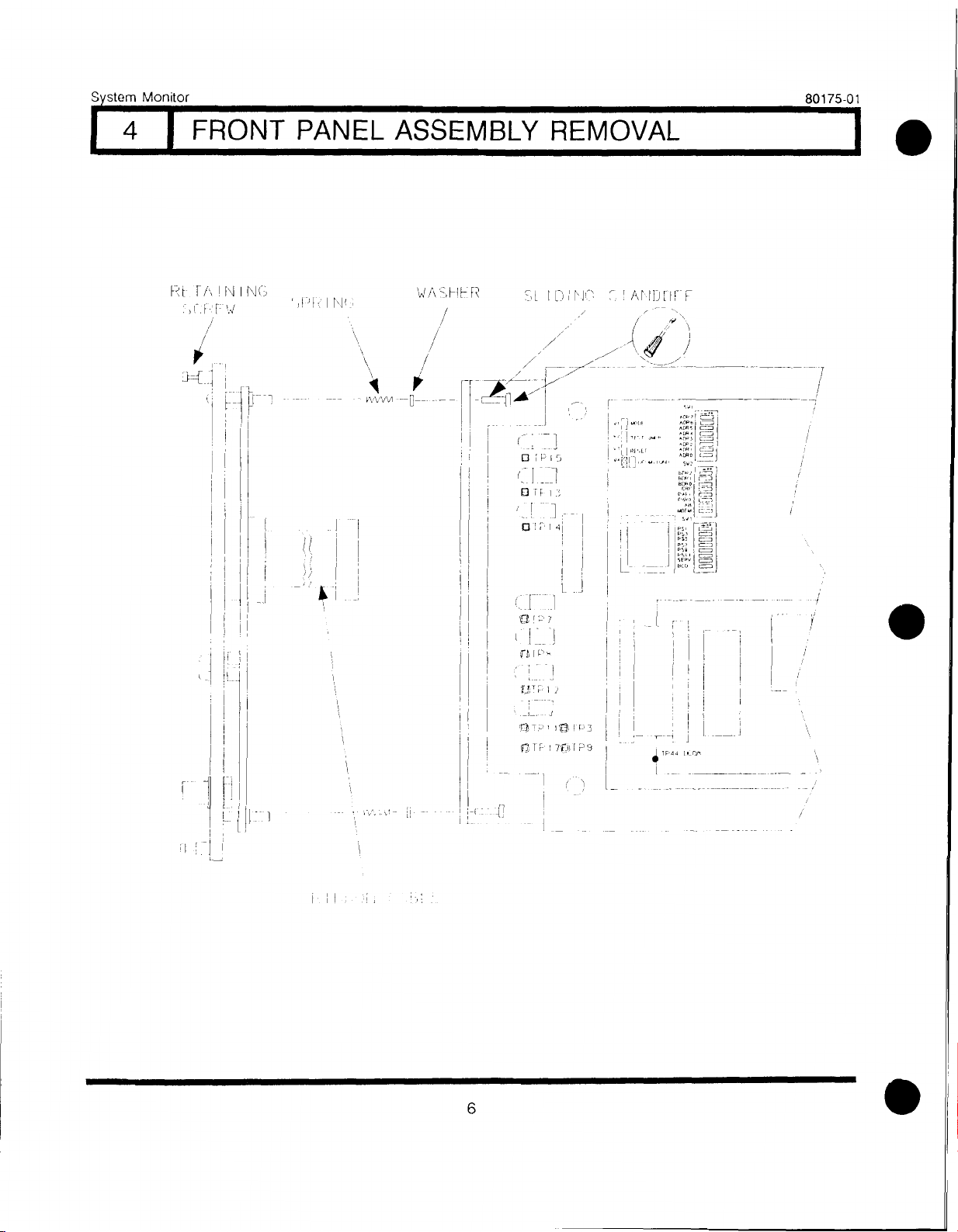
4I FRONT PANEL ASSEMBLY REMOVAL
Rr FA!NINIC3 !Pk I Nti:
I!
IDIGL I Aril-J[1r F
I•
•
frP
53TP ,131-p3
171 TF- I7th1P9
II
6

System Monitor 80175-01
5I OK RELAY CONFIGURATION
THE FOLLOWING DIAGRAM SHOWS THE FUNCTIONAL CONCEPT or THE OK RBLAI
FOR MOPE DETAIL __r FR TO SCHFMATIC ISEE
•
•
MONITOR
OK RELA
DRIVE
MONI1OR
ON RPLAY
DRIVE
MONITOR
N
OK RELAY
DRIVE
PEL A r r.:(DN ,
0- fk I1.1,
.4.YM
NO (2,K,
ARM STATE
NC
OK BUS
INHIBIT
CONTACT
CLOSURE
ROWER UP
INHIBIT
POWER
_J INPUI
MODULE
1No
1(- AkM
ICH
_LI \7 I
uK HFLA
NORMALLY ENERGIZED)
S'ESTEM
MOUITOR
NOTE -A\
RELAY CONTACTS
IN NO! Ce
ci-)HPITION
r,r
7

System Monitor 80175-01
6I COMMUNICATIONS PROCESSOR INTERFACE I
i,0
iit? phi
„ci
4,144420
Communications processor systems used with 3300 systems should all
operate from the same power source. If they do not and if the 3300 system
power goes off, the computer screen will indicate system OK and displayed
meter values will be approximately 7% of full scale.
4JG.' 03 o f hAM C SIGNAL
PoWFP NPU I
MoD.
B
w)
I
!)-(NAM I C DA 79._ m/...:ACE:=--
OMMUN ICAr 101%15
PPOCE F,OR
7pi-IT=IIENT DATA MAV.;'"-JER
ii_:, 1.1 1 'I "
p.1.11.1,...1..:,..p.ir.,,!i,,,rmyirri
i:„.ip,....i,,lidLikiHill ........_....
:M. p LPMPMEP
TO NEXT
RACK i tl
DAISY
CHAIN
CEE13)
1•
KETPHAfy.:•p
8
•
•

•
•
•
System Monitor 80175-01
6I COMMUNICATIONS PROCESSOR INTERFACE I
MONITOR/1
4 A
MONITOR#2 MONITOR#N
*CONNECTIONS TYPICAL ON AL:_ MONITORS
POSITION ENABLE - 4
BUFFERED DATA SELECT
BAPKPLANf
SYSTEM
MONITOR
STATIC DATA OUT
BUFFERED TRANSDUCER CED
BUFFERED TRAN'T,DErhE CR2
BUFFERED STATIC DATA
DATA SEl EAT
mON1 TOf FIFCS
COMMUNICATION'T,
PROCESSOR
▶
9

System Monitor 80175-01
71 PERFORMANCE TESTING
L
!RIP WI !III I
t!!POINT Afl.PiSl'ir
r---1
SYSTEM
MON I Ti)k
-------
ADVEhT 15`All.N
flyNAmiL
1.
("Fa
?1,4 •
•
I.CO (.4.1
TEP
2
Vr JUMPE I H l EM MON I T OF< ALJ1)
POWER SUPPL MU •`) I BE SETT TO F.AW.
VOLTAGE (-i8 VDC OR -24 VDC) OR
SUPPLIES OK LED WILL NOT GO ON.
I. -1.- REFER To POWEP
sur2,pt_ !AL
II () / 2 2 () Vt.(
10

System Monitor 80175-01
•1
•
•
8I KEYPHASOR PERFORMANCE TEST
NOTES: 1 THE FOLLOWING PROCEDURE FOR TESFIN(.; KE-(PHASOR 1 IS TYPICAL
FOR TESTING KEYPHASOR 2
2. MACHINE ASSOCIATED WITH KEYPHASOR UNDER TEST SHOULD BE
RUNNING DURING THIS PROCEDURE. IF MACHINE IS NOT TURNING.
SIMULATE RUNNING MACHINE INPUT FROM FUNCTION GENERATOR OR
TK3 TEST KIT.
MEASURE KEYPHASOR 1 POWER AT POWER INPUT MODULE Ket POWER TERMINAL.
TOLERANCE IS -23.7 ! 0 t; VDC
(-17.85 I 0.45 VDC FOR 3000 PROSIMI1OR,
Igmaalf&vit__
IVOLTAGF HI
/\ TOLERANrI
•••., ! /
,.//
VOL1AGE OU1 -
OF fOLERANCE
MP. tlo To
STEP 5
11
-• -

System Monitor 80175-01
8I KEYPHASOR PERFORMANCE TEST
DICONNECI WIRE: FROM K01 POWER /ND MEASURE VOLTAGE AT
POWER II\PJT MODULE TERMINAL. MCASUPFMENT SHOULD MEET
-HA FRANCE SPE:CH:ILL) IN 1.
_, _.... .
t!gt p iq
l
-,--.e5.:7,c,cc,c41
OK fr
i-CEL4Y ,6 00110 11( .r.)I
vf)LIA6L
OU1 OF
toLERANCE
VOL. 1 ACE
IN TnLERANCE
1110.- 60 TO STEP 4
LOO',FH 1.:H, PULL POWER INPUT MODULE._ Our FkOM
OF- I-/AMINF CABLIM6 AND (.0NNECIION-'=, 7!EiWEEN
MODULI PACL
MlihJllt ID MC,
WARNING
HIGH VOLTAGE LEVELS ARE
PRESENT THAT COULD CAUSE
SERIOUS INJURY.
i'")WL i INPUI MOWLE
CAI3L INO
DEFECTIVE REPAIR/REPLACE I
CABLE OR
CONNECTION
1•
12
•

•
Sstem Monitor
8
80175-01
KEYPHASOR PERFORMANCE TEST
RECONNECT WIRE AT KOI POWER TERMINAL. DISCONNECT WIRE AT -VT
(-18 vDC OR -24 VDC) TERMINAL OF PROXIMITOR AND MEASURE VOLTAGE
AT WIRE_ VOLTAGE SHOULD MEET TOLERANCE LISTED IN STEP I
REPAIR FAULTY
FIELD WIRING
VOLTAGE
OUT OF
TOLERANCE
4
0
VOLTAGE. IN -------------
-\TOLERANCE REPLACE
.1) PROXIMITOR
13
This manual suits for next models
1
Table of contents
Other Bently Nevada Measuring Instrument manuals

Bently Nevada
Bently Nevada 3300/50 User manual

Bently Nevada
Bently Nevada 3300/20 User manual

Bently Nevada
Bently Nevada 3300/15 User manual

Bently Nevada
Bently Nevada Velomitor Sensor User manual

Bently Nevada
Bently Nevada 3300/48 User manual

Bently Nevada
Bently Nevada Ranger Pro 70M300 User manual

Bently Nevada
Bently Nevada 3300/15 User manual

Bently Nevada
Bently Nevada 3300/40 User manual

Bently Nevada
Bently Nevada 3300/70 User manual


