80178-01 Dual Thrust Monitor Operation
2MONITORFUNCTIONS
DUAL THRUST POSITION - Thrust position is the average position, or change in position, of a rotor in the
axial direction with respect to some fixed reference. The Dual Thrust Position Monitor provides continuous
thrust position monitoring on 2 channels (A & B) for redundant protection. Normal thrust direction can be
toward or away from the probe face. AND voting logic ensures that failure of one channel will not give a false
Danger alarm. OR voting logic allows for two independent thrust channels in less critical applications.
PROBE GAP VOLTAGE - Probe gap is measured as a negative dc voltage that is directly proportional to the gap
distance between the face of a proximity probe and the surface being monitored. Probe gap voltage for each
channel is displayed on the front panel meter by pressing the GAP switch.
OK - When the proximitor output voltage is within its upper/ lower limits, the transducer is defined as OK. The
OK detection circuit controls the channel OK LED and the monitor relay drive to the OK relay. If the monitor
has the latching OK option, a System Reset is required to reset the OK function.
OK RELAY - The OK Relay is located on the Power Input Module. Every channel in the rack must be OK or
bypassed to energize the OK Relay.
ALARM - Pressing the ALERT and DANGER switches on the front panel of the monitor causes the cor-
responding Alert (first-level alarm) or Danger (second-level alarm) setpoints on each channel to be displayed on
the front panel meter. ALERT and DANGER LEDs light when the thrust position signal level exceeds preset
levels for the selected time delay, and appropriate ALERT and DANGER alarm relay contacts are activated.
Voting logic options determine when the Danger relay contacts are activated.
FIRST OUT - Separate First Out circuits exist for Alert and Danger alarms. A monitor with First Out option
selected flashes a channel alarm LED if that monitor was the first channel in the rack to go into alarm. Pressing
the RESET switch acknowledges the First Out.
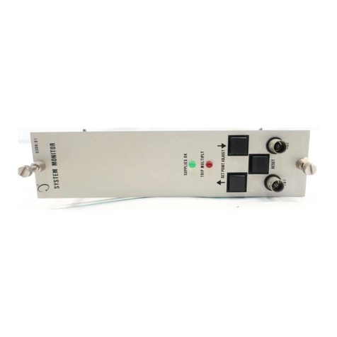
ALARM RELAYS - Monitor alarms can be programmed for either latching or nonlatching mode. In the non-
latching mode, the alarm resets automatically when the alarm condition no longer exists. In the latching mode,
the alarm condition must he reset manually by pressing the RESET switch on the front panel of the System
Monitor (or by closing external Reset contacts). The alarm will not reset if the alarm condition still exists.
DANGER BYPASS - For maintenance functions, a DANGER BYPASS switch on the monitor circuit board is set
to inhibit the Danger relay drive. This function turns on the BYPASS LEDs. Other front panel functions arc
not affected. This function can be disabled using a jumper within the monitor.
BUFFERED OUTPUT - The Channels A and B coaxial cable connectors on the front panel of the monitor and
terminals on the Signal Input Relay Module provide buffered signals from respective channel transducers. These
connectors can be used for connection of external equipment.
RECORDER OUTPUT - A recorder output is provided for each channel. Depending on the option selected, the
recorder output levels, proportional to full scale, are either 0 to -10 Vdc, +1 to +5 Vdc, or +4 to +20 mA.
SELF TEST - The monitor has three categories of self test: cyclic, power-up, and user-invoked.
•Power-up self test is performed automatically each time the monitor power is turned on. A series of
basic tests and transducer OK tests arc performed.
• Cyclic self test is performed automatically during monitor operation. Errors encountered during cyclic
tests disable the monitor, and flash an LCD bargraph error code. Should the error be intermittent, the
monitor will return to operation, hut the error codes are stored for retrieval during user-invoked self
tests. Stored error codes are indicated by the OK LEDs flashing at 5 Hz provided that the channel is
()K.
•User-invoked test performs power-up self test and allows error messages stored during cyclic tests to 1-
read and cleared. Stored errors are annunciated by the OK LEDs flashing at 5 Hz and the error codt. ;
displayed on the front panel LCD bargraph.
2


