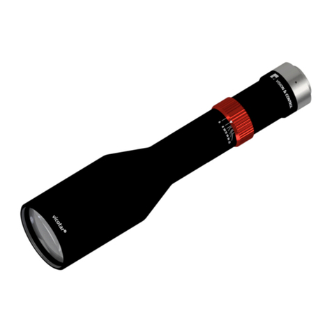
Bently Nevada Velomitor Sensor User manual

Artisan Technology Group is your source for quality
new and certied-used/pre-owned equipment
• FAST SHIPPING AND
DELIVERY
• TENS OF THOUSANDS OF
IN-STOCK ITEMS
• EQUIPMENT DEMOS
• HUNDREDS OF
MANUFACTURERS
SUPPORTED
• LEASING/MONTHLY
RENTALS
• ITAR CERTIFIED
SECURE ASSET SOLUTIONS
SERVICE CENTER REPAIRS
Experienced engineers and technicians on staff
at our full-service, in-house repair center
WE BUY USED EQUIPMENT
Sell your excess, underutilized, and idle used equipment
We also offer credit for buy-backs and trade-ins
www.artisantg.com/WeBuyEquipment
REMOTE INSPECTION
Remotely inspect equipment before purchasing with
our interactive website at www.instraview.com
LOOKING FOR MORE INFORMATION?
Visit us on the web at www.artisantg.com for more
information on price quotations, drivers, technical
specications, manuals, and documentation
Contact us: (888) 88-SOURCE | sales@artisantg.com | www.artisantg.com
SM
View
Instra

Part Number 100076-01
Rev. H (08/07)
Bently Nevada™ Asset Condition Monitoring
Operation Manual
330500 Velomitor® Sensor, 330525 Velomitor XA
Sensor, 330530 Radiation Resistant Velomitor Sensor
Artisan Technology Group - Quality Instrumentation ... Guaranteed | (888) 88-SOURCE | www.artisantg.com

330500 Velomitor Sensor, 330525 Velomitor XA Sensor, 330530 Radiation Resistant Velomitor Sensor Operation Manual
ii
Copyright © 1991. Bently Nevada LLC.
All rights reserved.
The information contained in this document is subject to change without notice.
The following are trademarks of General Electric Company in the United States and other
countries:
ACM, Actionable Information, Actionable Information to the Right People at the Right
Time, ADRE, Asset Condition Management, Asset Condition Monitoring, Bently ALIGN,
Bently BALANCE, Bently DOCUVIEW, Bently LUBE, Bently Nevada, Bently PERFORMANCE,
Bently RELIABILITY, CableLoc, ClickLoc, Data Manager, Decision Support, DemoNet,
Dynamic Data Manager, Engineer Assist, FieldMonitor, flexiTIM, FluidLoc, Helping You
Protect and Manage All Your Machinery, HydroScan, HydroView, Key ∅, Keyphasor,
Machine Condition Manager 2000, MachineLibrary, Machine Manager, MicroPROX, Move
Data, Not People, Move Information, Not Data, NSv, Prime Spike, PROXPAC, Proximitor,
REBAM, RuleDesk, SE, Seismoprobe, Smart Monitor, Snapshot, System 1, System
Extender, TDXnet, TDIXconnX, The Plant Asset Management Company, TipLoc, TorXimitor,
Transient Data Manager, Trendmaster, TrimLoc, Velomitor
The following are trademarks of the legal entities cited:
Crescent® is a trademark of Crescent Tool and Horseshoe Corporation.
Loctite® is a trademark of Henkel Corporation.
Contact Information
The following ways of contacting Bently Nevada are provided for those times when you
cannot contact your local representative:
Mailing Address 1631 Bently Parkway South
Minden, Nevada USA 89423
USA
Telephone 1.775.782.3611
1.800.227.5514
Fax 1.775.215.2873
Internet www.ge-energy.com/bently
Artisan Technology Group - Quality Instrumentation ... Guaranteed | (888) 88-SOURCE | www.artisantg.com

iii
Additional Information
Notice:
This manual does not contain all the information required to operate and maintain
the product. Refer to the following manuals for other required information.
3500/42M Proximitor®/Seismic Monitor Operation and Maintenance
Manual (Part Number 143489-01)
3300/55 Dual Velocity Monitor Operation Manual
(Part Number 130747-01)
3300/55 Dual Velocity Monitor Maintenance Manual
(Part Number 130748-01)
Product Disposal Statement
Customers and third parties, who are not member states of the European Union, who are
in control of the product at the end of its life or at the end of its use, are solely
responsible for the proper disposal of the product. No person, firm, corporation,
association or agency that is in control of product shall dispose of it in a manner that is
in violation of any applicable federal, state, local or international law. Bently Nevada LLC
is not responsible for the disposal of the product at the end of its life or at the end of its
use.
Artisan Technology Group - Quality Instrumentation ... Guaranteed | (888) 88-SOURCE | www.artisantg.com

330500 Velomitor Sensor, 330525 Velomitor XA Sensor, 330530 Radiation Resistant Velomitor Sensor Operation Manual
iv
Contents
1. Operating Information............................................................................... 1
1.1 Application..............................................................................................................................................................1
1.2 Principle of Operation........................................................................................................................................1
1.3 Ordering Options and Accessories .............................................................................................................3
1.3.1 Velomitor® Sensor Options ......................................................................................................................3
1.3.2 Mounting Adapters — Option AA............................................................................................................4
1.3.3 Agency Approvals — Option BB ..............................................................................................................5
1.4 Compatible Monitoring Systems and Connections.............................................................................5
1.5 Cable Options........................................................................................................................................................9
1.6 Transducer Accessories ................................................................................................................................ 16
2. Installation .................................................................................................17
2.1 Receiving Inspection....................................................................................................................................... 17
2.2 Installing the Transducer.............................................................................................................................. 17
2.2.1 Positioning the Sensor.............................................................................................................................. 17
2.2.2 Mounting......................................................................................................................................................... 17
2.3 Installing Connecting Cable......................................................................................................................... 18
2.3.1 Routing Cable (for Velomitor® Sensor 330500) ........................................................................... 19
2.3.2 Routing Cable (for Velomitor® Sensor 330525) ........................................................................... 19
2.3.3 Routing Cable (for Velomitor® Sensor 330530) ........................................................................... 19
2.3.4 Routing Armored Cable............................................................................................................................ 22
2.3.5 Sealing the Connecting Cable............................................................................................................... 22
3. Maintenance ..............................................................................................23
3.1 Test Setup............................................................................................................................................................. 24
3.2 Performance Test Procedure...................................................................................................................... 26
3.3 Polarity Test Procedure.................................................................................................................................. 26
3.4 Installation Note................................................................................................................................................ 27
4. Field Testing and Troubleshooting ........................................................28
4.1 Fault Indication #1 Cause/Solution ......................................................................................................... 28
4.2 Fault Indication #2 Cause/Solution ......................................................................................................... 29
4.3 Fault Indication #3 Cause/Solution ......................................................................................................... 29
5. Specifications.............................................................................................30
5.1 Standard Use Specifications (330500, 330525) ................................................................................. 30
5.1.1 Electrical.......................................................................................................................................................... 30
5.1.2 Environmental .............................................................................................................................................. 30
5.1.3 Mechanical..................................................................................................................................................... 30
5.2 Nuclear Use Specifications (330530)....................................................................................................... 31
5.2.1 Electrical.......................................................................................................................................................... 31
5.2.2 Environmental .............................................................................................................................................. 32
5.2.3 Mechanical..................................................................................................................................................... 32
5.3 Mechanical Drawing (330500, 330530) ................................................................................................. 33
5.4 Mechanical Drawing (330525).................................................................................................................... 34
Artisan Technology Group - Quality Instrumentation ... Guaranteed | (888) 88-SOURCE | www.artisantg.com

Section 1 - Operating Information
1
1. Operating Information
1.1 Application
Velocity sensors measure machinery casing vibration and are used on machines
where using eddy current proximity transducers are not practical. Typical
applications include pumps, electric motors, compressors, and fans.
The 330525 Velomitor® XA Sensor is designed for applications where a
transducer housing is either unnecessary or not desired.
The 330530 Radiation-Resistant Velomitor® Sensor is designed for applications
requiring a resistance to the effects of gamma-radiation.
Application Alert: Casing measurements may not be appropriate for
some machinery protection applications.
If you measure the velocity of casing vibration to protect machinery, evaluate the
usefulness of the measurement for each application. Most common machine
malfunctions, such as unbalance or misalignment, occur on the rotor and
originate as an increase (or at least a change) in rotor vibration. In order for any
casing measurement alone to be effective for overall machine protection, the
machine must faithfully transmit a significant amount of rotor vibration to the
machine casing or mounting location of the sensor.
Exercise care when physical installing of the sensor on the bearing housing or
machine casing. Section 2 tells how to install the sensor.
Application Alert: Improper installation may result in a decrease in the
velocity sensor's amplitude and frequency response and/or generate
false signals that do not represent actual vibration.
1.2 Principle of Operation
The Velomitor® Sensor is a piezoelectric velocity sensor. The sensing element of
the device is a piezoelectric ceramic shear-mode element and electronics. When
subjected to machinery vibration, this system exerts a force on the piezoelectric
ceramic, which generates a signal proportional to that force. The sensor
internally amplifies and integrates this signal to produce a low-noise output signal
that is proportional to velocity.
Application Advisory: A sudden mechanical impulse may cause the
piezoelectric velocity sensor to generate a low frequency signal that
does not represent actual machinery vibration. This signal may change
the state of alarm and/or danger relays.
Artisan Technology Group - Quality Instrumentation ... Guaranteed | (888) 88-SOURCE | www.artisantg.com

330500 Velomitor Sensor, 330525 Velomitor XA Sensor, 330530 Radiation Resistant Velomitor Sensor Operation Manual
2
The Velomitor® Sensor is designed to monitor vibration in frequencies ranging
from:
• 330500: 4.5 Hz to 5 kHz
• 330525: 4.5 Hz to 2 kHz
• 330530: 4.5 Hz to 5 kHz
The sensor has a calibrated sensitivity of 100 mV/in/s (4 mV/mm/s) and some of
the sensors can measure velocities up to 50 in/sec pk (1270 mm/s pk) – see the
specification section for details. The stainless steel casing protects the Velomitor®
Sensor in highly corrosive environments. The operating temperature range is from
-67°F to 250°F (-55°C to 121°C).
Traditional velocity sensors consist of either a moving wire coil surrounding a
fixed magnet or a fixed wire coil surrounding a moving magnet. The Velomitor®
Sensor is more accurate than traditional velocity sensors. Because the
Velomitor® Sensor contains no moving parts, it is also more durable and less
sensitive to transverse motion than traditional seismic transducers. Its
piezoelectric sensing element and solid-state circuitry let the Velomitor® Sensor
withstand years of continuous use.
The Velomitor® Sensor is a two-wire device that requires an external power
supply. The power supply must provide a DC voltage of 22 to 30 Volts and a
current of 10 mA. A constant current diode must be used to limit the current to
the sensor to 2.5 to 6 mA. Figure 1-1 shows a simple block diagram of the
Velomitor® Sensor system.
(1) Velomitor®
Sensor
(2) Pin A
(3) Pin B
(4) Shielded cable
(5) “A” white
(6) “B” black
(7) “SHLD”
(8) Constant current
source
(9) DC voltage supply
Figure 1-1.
The Velomitor® Sensor internal circuitry automatically sets the DC output bias
when a constant current is supplied. The DC bias and AC signal appears between
pins "A" and "B".
Artisan Technology Group - Quality Instrumentation ... Guaranteed | (888) 88-SOURCE | www.artisantg.com

Section 1 - Operating Information
3
Application Alert: Use a constant current diode or other current-
regulating circuitry to provide power to the Velomitor® Sensor. Failure
to do so may result in damage to the device and/or improper operation.
Compatible Bently Nevada monitoring systems provide the power required by the
Velomitor® Sensor without the need for additional external circuitry.
1.3 Ordering Options and Accessories
1.3.1 Velomitor® Sensor Options
When ordering a Velomitor® Sensor you may choose from the following list of
options.
Table 1-1 Ordering Information
Part Number Options
330500 AA BB
Description
01 1/2 - 20 UNF P/N: 89409-01
02 M8 X 1 P/N: 89410-01
03 1/4 - 28 UNF P/N: 89411-01
04 1/4 - 20 UNC P/N: 89412-01
05 1/4 - 18 NPT P/N: 89413-01
06 5/8-18 UNF P/N: 04300015
07 3/8-16 UNC P/N: 165025-01
08 1/2-13 UNC P/N: 161191
00 No Approvals
04 Multiple Approvals
Artisan Technology Group - Quality Instrumentation ... Guaranteed | (888) 88-SOURCE | www.artisantg.com

330500 Velomitor Sensor, 330525 Velomitor XA Sensor, 330530 Radiation Resistant Velomitor Sensor Operation Manual
4
Part Number Options
330525 AA
Description
00 No Approvals
01 CSA Approvals
02 ATEX Approvals
Part Number Options
330530 AA
Description
01 1/2 - 20 UNF P/N: 89409-01
02 M8 X 1 P/N: 89410-01
03 1/4 - 28 UNF P/N: 89411-01
04 1/4 - 20 UNC P/N: 89412-01
05 1/4 - 18 NPT P/N: 89413-01
06 5/8-18 UNF P/N: 04300015
07 3/8-16 UNC P/N: 165025-01
08 1/2-13 UNC P/N: 161191
1.3.2 Mounting Adapters — Option AA
The base of the 330500 and 330530 Velomitor® Sensor are machined with a 3/8-
24 internal thread that will accommodate a variety of purchased or customer-
manufactured mounting studs. Bently Nevada offers the 7 adapter studs listed in
Table 1-1. You can order one stud with each transducer or purchase the studs
separately. Table 1-1 also lists Bently Nevada part numbers used for ordering
separate adapter studs.
The base of the 330525 Velomitor® Sensor is machined with a 1/4-18 NPT
external thread.
Artisan Technology Group - Quality Instrumentation ... Guaranteed | (888) 88-SOURCE | www.artisantg.com

Section 1 - Operating Information
5
1.3.3 Agency Approvals — Option BB
Consult your local Bently Nevada sales representative for information regarding
hazardous area approvals.
1.4 Compatible Monitoring Systems and Connections
The Velomitor® Sensor is compatible with the Bently Nevada 3500/42
Proximitor®/Seismic Monitor and 3300/55 Dual Velocity Monitor.
For more information on the 3500/42 and 3300/55 please refer to Bently Nevada
data sheets 143694-01 and 141516-01, respectively.
Connections to the "A" and "B" terminals of the Velomitor® Sensor are made
through the terminal connector of the interconnect cable. At the monitor end of
the cable, connect the cable "A" lead to the "A" terminal on the monitor and the
"B" lead to the "B" terminal. The terminal connections appear in Figures 1-2
through 1-4. Refer to the 3500/42 and 3300/55 Monitor Manuals (P/N’s 143489-
01, 130747-01 and 130748-01, respectively) for further information.
Artisan Technology Group - Quality Instrumentation ... Guaranteed | (888) 88-SOURCE | www.artisantg.com

330500 Velomitor Sensor, 330525 Velomitor XA Sensor, 330530 Radiation Resistant Velomitor Sensor Operation Manual
6
(1) 3500/42 Prox/Velom I/O Module with internal terminations, Velomitor®
Sensor input.
(2) Wiring shown for Channels 1 and 2. Wiring typical for Channels 3 and 4.
(3) Channel 1 Velomitor® Sensor
(4) Channel 2 Velomitor® Sensor
(5) Velomitor® Sensor top view
Figure 1-2. 3500/42 Monitor with Prox/Velom I/O Module
Artisan Technology Group - Quality Instrumentation ... Guaranteed | (888) 88-SOURCE | www.artisantg.com

Section 1 - Operating Information
7
(1) Wiring shown for Channels 1 and 2. Wiring typical for Channels 3
and 4.
(2) 3500 Prox/Velom I/O Module with internal terminations, Velomitor®
Sensor input with external barriers.
(3) Safe area or Zone 2, Division 2
(4) Hazardous area
(5) Channel 1 Velomitor® Sensor
(6) Channel 2 Velomitor® Sensor
(7) Velomitor® Sensor top view
Figure 1-3. 3500/42 Monitor with Prox/Velom I/O Module with External
Barriers
Artisan Technology Group - Quality Instrumentation ... Guaranteed | (888) 88-SOURCE | www.artisantg.com

330500 Velomitor Sensor, 330525 Velomitor XA Sensor, 330530 Radiation Resistant Velomitor Sensor Operation Manual
8
(1) Signal input relay module location
(2) Channel A recorder output
(3) Channel B recorder output
(4) Alert relay contacts
(5) Danger relay contacts
(6) Signal input relay module, dual relays
(7) Channel A Velomitor® Sensor
(8) Channel B Velomitor® Sensor
Figure 1-4. 3300 System Connections (3300/55 Monitor)
Artisan Technology Group - Quality Instrumentation ... Guaranteed | (888) 88-SOURCE | www.artisantg.com

Section 1 - Operating Information
9
1.5 Cable Options
The Velomitor® Sensor requires a two-conductor cable. We recommend using
shielded cable to minimize noise interference. Table 1-2 describes the Bently
Nevada cables used with the 330500 Velomitor® Sensor, Table 1-3 describes the
cables used with the 330525 Velomitor® Sensor, and Table 1-4 describes the
cables used with the 330530 Radiation Resistant Velomitor® Sensor. Figures 1-5
through 1-9 show the configuration of the cable and connector for each of the
sensors.
Table 1-2. 330500 Velomitor® Sensor Interconnect Cable and
Accessories
APPLICATION P/N CABLE DESCRIPTION
Standard Temperature
Unarmored Cable 9571-AA Shielded 22 AWG cable with moisture-
resistant female socket connector at
transducer end, ring lugs at monitor end.
Standard Temperature
Armored Cable 84661-AA Same as 9571-AA but with flexible
stainless steel armored cable.
Cable for use with weather-
proof housing 89477-AA Two-conductor shielded cable with a
connector adapted for use with the 21128
Velocity Transducer Housing Assembly.
Bulk Cable 02173006 Two-conductor shielded 18 AWG bulk
cable. Specify number of feet.
Spare Connector 00531061 Velomitor® Sensor Cable Connector
Spare Connector Clamp 00530574 Connector Clamp
Table 1-3. 330525 Velomitor® Sensor Interconnect Cable and
Accessories
APPLICATION P/N CABLE DESCRIPTION
Standard Temperature
Armored Cable 106765-AA Flexible Stainless Steel Armored Cable
Bulk Cable 02173007 Two-conductor shielded 22 AWG bulk
cable. Specify number of feet.
Spare Boot 03839144 Fluorosilicone Elastomer Boot
Spare Boot Clamps 03839142
03839143 Bottom Clamp
Top Clamp
Table 1-4. 330530 Velomitor® Sensor Interconnect Cable and Accessories
APPLICATION P/N CABLE DESCRIPTION
Standard Temperature Unarmored
Cable 330533-AA Shielded 18 AWG cable with moisture-
resistant female socket connector at
transducer end, ring lugs at monitor end.
Bulk Cable 175873 Two-conductor shielded 18 AWG bulk
cable. Specify number of feet.
Spare Connector 00531061 Velomitor® Sensor Cable Connector
Artisan Technology Group - Quality Instrumentation ... Guaranteed | (888) 88-SOURCE | www.artisantg.com

330500 Velomitor Sensor, 330525 Velomitor XA Sensor, 330530 Radiation Resistant Velomitor Sensor Operation Manual
10
PART NUMBER 9571 - AXX (SEE NOTE)
NOTE
ORDER IN INCREMENTS OF 1.0 FOOT (0.30 m)
EXAMPLE:
0 2 2 FEET (0.61 m)
2 5 25 FEET (7.6 m)
MINIMUM LENGTH = 2 FEET (0.61 m)
MAXIMUM LENGTH = 99 FEET (30 m)
(1) Cable 2-22 AWG conductor shielded, Teflon insulated
(2) Clear shrink tubing, 63.5 mm (2.5 in)
(3) 51 mm ± 13 mm (2.00 in ± 0.5 in)
(4) “A”, white
(5) “B”, black
(6) 126 mm ± 13 mm (5.00 in ± 0.5 in)
(7) SHLD, green
(8) Overall length ± 150 mm (± 6.0 in)
Figure 1-5. 9571 Cable for use with 330500 Velomitor® Sensor
Artisan Technology Group - Quality Instrumentation ... Guaranteed | (888) 88-SOURCE | www.artisantg.com

Section 1 - Operating Information
11
PART NUMBER 84661 - AXX (SEE NOTE)
NOTE
ORDER IN INCREMENTS OF 1.0 FOOT (0.30 m)
EXAMPLE:
0 3 3 FEET (0.91 m)
2 5 25 FEET (7.6 m)
MINIMUM LENGTH = 3 FEET (0.91 m)
MAXIMUM LENGTH = 96 FEET (29 m)
(1) Stainless steel armor over cable
(2) Clear shrink tubing, 63.5 mm (2.5 in) typical
(3) 635 mm ± 76 mm (25.0 in ± 3.00 in)
(4) 51 mm ± 13 mm (2.00 in ± 0.5 in)
(5) “A”, white
(6) “B”, black
(7) 126 mm ± 13 mm (5.00 in ± 0.5 in)
(8) SHLD, green
(9) Overall length ± 150 mm (± 6.0 in)
Figure 1-6. 84661 Cable for use with 330500 Velomitor® Sensor
Artisan Technology Group - Quality Instrumentation ... Guaranteed | (888) 88-SOURCE | www.artisantg.com

330500 Velomitor Sensor, 330525 Velomitor XA Sensor, 330530 Radiation Resistant Velomitor Sensor Operation Manual
12
PART NUMBER 89477 - AXX (SEE NOTE)
12
3
4
5
NOTE
ORDER IN INCREMENTS OF 1.0 FOOT (0.30 m)
EXAMPLE:
1 2 12 FEET (3.7 m)
2 5 25 FEET (7.6 m)
MINIMUM LENGTH = 2 FEET (0.61 m)
MAXIMUM LENGTH = 99 FEET (30 m)
(1) Schematic
(2) “A”, white
(3) “B”, black
(4) SHLD, green
(5) Overall length ± 150 mm (± 6.0 in)
Figure 1-7. 89477 Cable for use with 330500 Velomitor® Sensor
Artisan Technology Group - Quality Instrumentation ... Guaranteed | (888) 88-SOURCE | www.artisantg.com

Section 1 – Operating Information
13
PART NUMBER 106765 - AXX (SEE NOTE)
1. 2-pin connector 8. 14.5 mm (0.57 in) maximum 15. Overall length ± 150 mm (± 6 in)
2. Stainless steel armor, FEP coated 9. Fluorosilicone elastomer oil-resistant boot 16. Shield
3. 7/8” single snap-grip hose clamp 10. 2-conductor shielded and jacketed cable 17. Green
4. 15/32” single snap-grip hose clamp 11. Approvals label 18. White
5. BN part number and serial number
label 12. “B”, black 19. Black
6. “A”, white 13. “SHLD”, green 20. Figure B, Wiring Diagram
7. 38.1 mm (1.50 in) maximum 14. Nickel-plated copper Teflon insulated ring terminal
(size #6 stud) typical, 3 places
Figure 1-8. 106765 Cable for use with 330525 Velomitor® Sensor
Artisan Technology Group - Quality Instrumentation ... Guaranteed | (888) 88-SOURCE | www.artisantg.com

330500 Velomitor Sensor, 330525 Velomitor XA Sensor, 330530 Radiation Resistant Velomitor Sensor Operation Manual
14
NOTE
ORDER IN INCREMENTS OF 3.0 METER (9.8ft)
EXAMPLE:
1 0 10 METER (33 ft)
2 5 25 METER (82 ft)
MINIMUM LENGTH = 1 METER (3.3 ft)
MAXIMUM LENGTH = 25 METER (82.0 ft)
Artisan Technology Group - Quality Instrumentation ... Guaranteed | (888) 88-SOURCE | www.artisantg.com

Section 1 – Operating Information
15
PART NUMBER 330533 - AXX (SEE NOTE)
NOTE
ORDER IN INCREMENTS OF 1.0 FOOT (0.30 m)
EXAMPLE:
0 2 2 FEET (0.61 m)
2 5 25 FEET (7.6 m)
MINIMUM LENGTH = 2 FEET (0.61 m)
MAXIMUM LENGTH = 99 FEET (30 m)
(1) Cable 2-18 AWG conductor shielded, Tefzel insulated
(2) Clear shrink tubing, 63.5 mm (2.5 in)
(3) 51 mm ± 13 mm (2.00 in ± 0.5 in)
(4) “A”, white
(5) “B”, black
(6) 126 mm ± 13 mm (5.00 in ± 0.5 in)
(7) SHLD, green
(8) Overall length ± 150 mm (± 6.0 in)
Figure 1-9. 330533 Cable for use with 330530 Velomitor® Sensor
Application Advisory: This cable is not like most other Velomitor
cables in that the shield and drain wire are connected to the sensor’s
connector. The sensor is connected to the machine that should be
correctly grounded. So the sensor is the primary shield grounding point.
See the special installation details in the section below.
Artisan Technology Group - Quality Instrumentation ... Guaranteed | (888) 88-SOURCE | www.artisantg.com
This manual suits for next models
5
Table of contents
Other Bently Nevada Measuring Instrument manuals

Bently Nevada
Bently Nevada 3300/48 User manual
Bently Nevada
Bently Nevada 3300/01 Series User manual

Bently Nevada
Bently Nevada 3300/70 User manual

Bently Nevada
Bently Nevada 3300/20 User manual

Bently Nevada
Bently Nevada Ranger Pro 70M300 User manual
Bently Nevada
Bently Nevada 3300/40 User manual

Bently Nevada
Bently Nevada 3300/50 User manual

Bently Nevada
Bently Nevada 3300/15 User manual

Bently Nevada
Bently Nevada 3300/15 User manual
