Benzlers BS Series Maintenance and service guide

Series BS
Installation & Maintenance

2

CONTENTS
3
PRODUCT SAFETY INFORMATION 2
1 INFORMATION ............................................................................................ 4
1.1 General information ........................................................................... 4
1.2 Safety warning Symbols .................................................................... 4
1.3 Weather Protection of Unit ................................................................. 5
1.4 Reading the Nameplate ..................................................................... 5
1.5 Marking ....................................................................................... 6
2 INSTALLATION ........................................................................................... 7
2.1 Safety Warning ................................................................................... 7
2.2 Prior to Installation ............................................................................. 7
2.3 Fitting of components to either the unit input or output shaft ............. 7
2.4 Lifting ................................................................................................. 8
2.5 Footmountedorangemountedunits .............................................. 8
2.6 Shaft mounted units ......................................................................... 10
2.7 Units for use in a potentially explosive atmosphere ......................... 10
3 LUBRICATION .......................................................................................... 11
3.1 General ............................................................................................ 11
3.2 Ventilator .......................................................................................... 11
3.3 Approved lubricants ......................................................................... 11
4 MOTOR CONNECTIONS ......................................................................... 12
5 STARTING UP .......................................................................................... 12
5.1 Prior to starting up ............................................................................ 12
5.2 Running-in .........................................................................................12
6 OPERATION ............................................................................................. 13
6.1 Noise ................................................................................................... 13
6.2 General Safety .................................................................................... 13
6.3 Initial start up for gear units operating in a potentially
explosive atmosphere ............................................................................... 13
7 MAINTENANCE 1...................................................................................... 14
7.1 Prior to any maintenance operations ............................................... 14
7.2 Oil plugs / Ventilator ......................................................................... 14
7.3 Maintaining lubrication ..................................................................... 14
7.4 Bearings ........................................................................................... 16
7.5 Oil Seals ........................................................................................... 16
7.6 Cleaning ........................................................................................... 16
8 FAULT DIAGNOSIS .................................................................................. 17
8.1 Gear unit problems ............................................................................. 17
APPENDIX 1 SHAFT ALIGNMENT .......................................................... 18
APPENDIX 2 ALTERNATIVE SHAFT FIXING METHODS ....................... 20
APPENDIX 2A TORQUE ARM DETAILS BS ............................................ 21
APPENDIX 3 THREE PHASE INDUCTION MOTOR INSTALLATION ..... 22
APPENDIX 4 APPROVED LUBRICATION ............................................... 23
APPENDIX 5 DECLARATION OF CONFORMITY ................................... 25
4
INFORMATION
1.1 General information
The following instructions will help you achieve a satisfactory installation of your Benzlers or Radicon gear unit, ensuring
the best possible conditions for a long and trouble free operation.
All units are tested and checked prior to despatch, a great deal of care is taken in packing and shipping arrangements to
ensure that the unit arrives at the customer in the approved condition.
Series BS gear units will perform satisfactorily if subjected to full load immediately after installation. However optimum
performanceisbestachievedbyaprocessofgradualloadincrements,uptothefullvalue,overtherst50hoursorsoof
their working life. During these early stages of running, sensible temperature may occur over many hours until the unit has
reacheditshighestefciency.
The gear unit must not be used until the machine it is incorporated in, has been shown to comply with EEC Machinery
Directive 2006/42/EC.
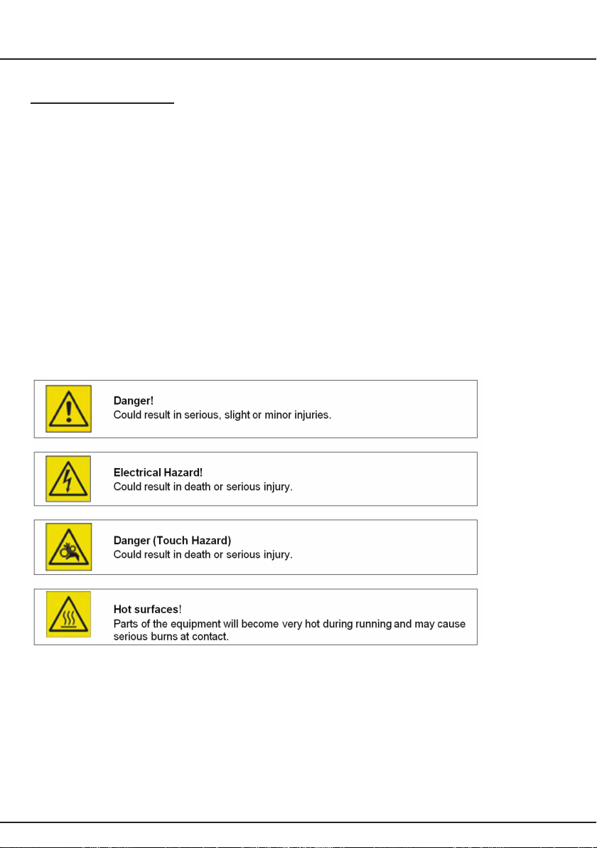
1.2 Safety warning Symbols
There are four different warning symbols used at the manual to mark out the hazardous moments that may cause risk of
human injury or equipment injuries.
5
INFORMATION
1.3 Weather Protection of Unit
All series BS units are provided with protection against normal weather conditions.
Where units are to operate in extreme conditions, or where they are to stand for long periods without running, e.g. during
plantconstruction,pleaseconsultyourlocalsalesofcesothatarrangementsforadequateprotectioncanbemade.
Gear units that are installed outdoors or have to work under adverse conditions, for example in hot, dusty or damp
premises,mustbettedwithappropriateprotection.Thecirculationofairaroundthegearunitmustnotbeobstructed,
however.
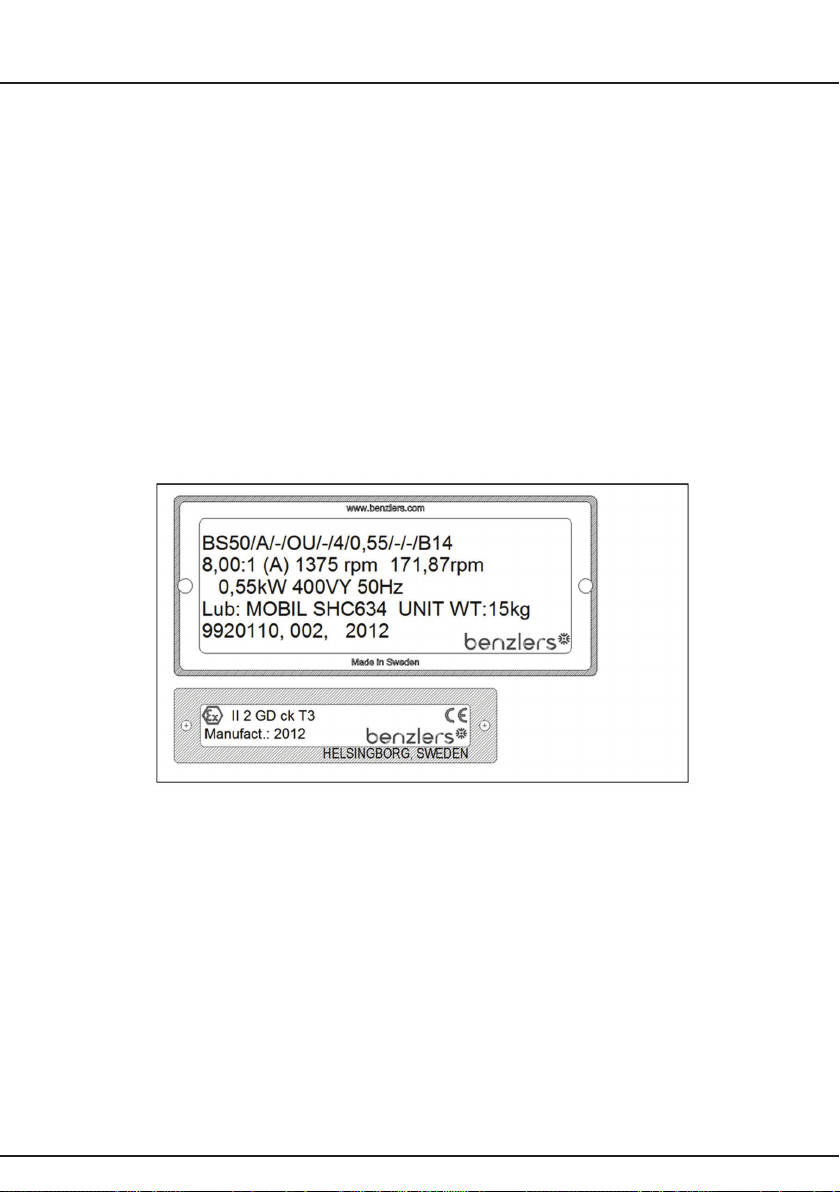
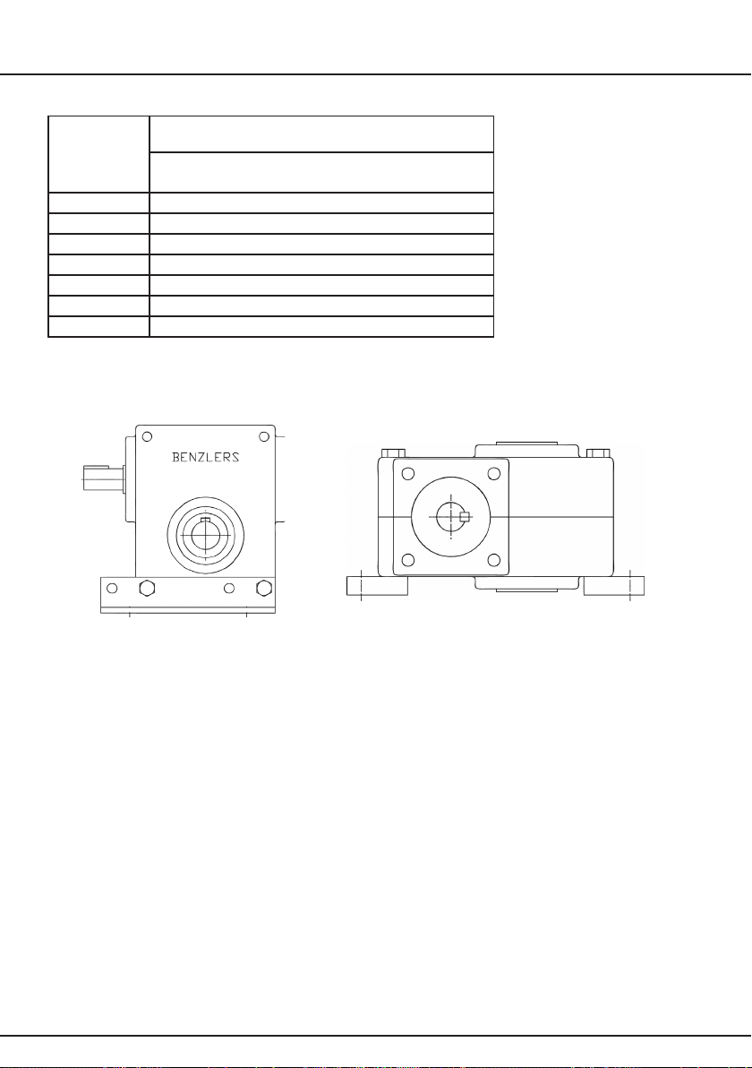
1.4 Reading the Nameplate
1.4.1 Unit Identication
When requesting further information or service support, quote the following information
from the nameplate:
Unit type (Model No.)
Order Number / Year of Manufacture
1.5 Lubrication Grade
SeriesBSwormgearunitsaresuppliedlubricatedforlife.(Factorylledwithsyntheticlubricant.)
The lubrication grade is marked on the nameplate. See Appendix 4 for type and quantity of lubricant.
6
INFORMATION
1.6 Marking
Gear units with -marking are especially selected for use as a component of an industrial system operating in a
potentially explosive atmosphere.
Provided they are correctly installed in accordance with these instructions (gear units only) they comply with the EU
directive 94/9/EC (ATEX 100a).
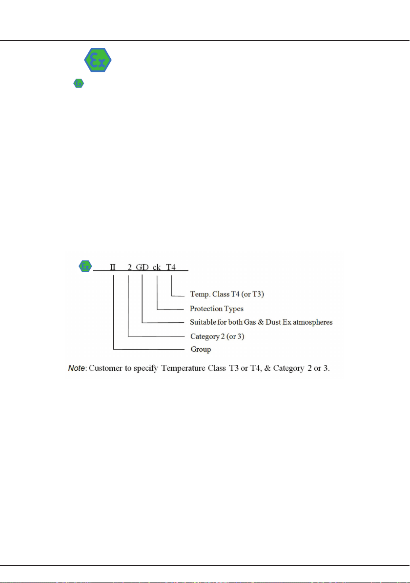
The units must be selected for use in potentially explosive atmospheres classied as Group II Cat 2 (zones 1 & 21)
orGroupIICat3(zones2&22).
Motors,couplings,oranyotherequipmentttedtothegearunitmustalsocomplywiththisdirective.
If the gear unit is supplied as a geared motor package it is important to check that the nameplates of the gear unit and the
motor(oranyotherequipmenttted)correspondswiththeclassicationofthepotentiallyexplosiveatmosphereinwhich
the unit is to be installed.
1.6.1 Understanding EU Directive 94/9/EC (ATEX 100a) Markings.
The product will be typically marked as shown:
7
INSTALLATION
2 Installation
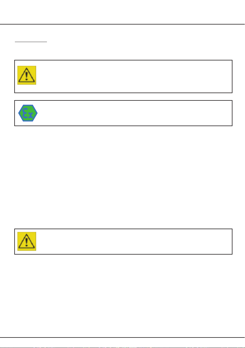
2.1 Safety Warning
NOTE!
The customer shall be responsible for the proper use of articles supplied by Benzlers or Radicon,
particularly rotating shafts between the driving and driven members, and the provision of safety
guarding. They shall not be responsible for any injury or damage sustained as a result of the improper
use of the articles supplied.
Attention is hereby drawn to the danger of using naked lights in proximity to openings in gearboxes
and gear units supplied by Benzlers or Radicon, and they shall not be liable for any claim for injury or
damage arising from any action in contravention of this warning.
2.2 Prior to Installation
1. Check that there are no damages at the gear unit.
2. Check that the gear unit and the motor name plate, matches the requirements of the machine the unit is to
be installed into.
3. Thoroughly clean the gearbox mounting surfaces that are to be used and the shafts of paint and anti-corrosion
agents, using a commercially available solvent. Ensure solvent does not make contact with the oil seals.
2.3 Fitting of components to either the unit input or output shaft
The input or output shaft extension diameter tolerance is to ISO tolerance j6 (for shaft diameter ≤40 mm) and k6
(for shaft diameter >40 mm). Fitted components should be to ISO tolerance K7.
1.Ensureshaftextensions,bores&keysetcarecleaned.
2. Items (such as gears, sprockets, couplings etc.) should not be hammered onto these shafts since this would damage
the shaft support bearings.
3.Itemsbeingttedmaybeheatedto80/100°Ctoaidassembly.
NOTE!
You must absolutely not use any violent forces!

8
INSTALLATION
2.4 Lifting
The gear motor must never be lifted by the lifting eye on the motor alone.
NOTE!
The gear motor must never be lifted by the lifting eye on the motor alone.
2.5 Foot mounted or ange mounted units
1.Ensurethebasefoundationmountingsurfaceisat
1
, vibration absorbing and torsionally rigid.
Note! Units on baseplates should, if possible, be mounted on the same bedplate as the prime mover.
2.Ifachainsprocketisttedtotheoutputshaft,thedirectionofpullshouldbechosensothatthegearhousingispressed
against the foundation.
3. Align unit (See Appendix 1).
Note! It is important to ensure when aligning unit on baseplate that all machined mounting points are supported over
their full area.
If steel packings are used, these should be placed either side of the foundation bolt as close as possible.
Duringnalboltingensuretheunitorbaseplateisnotdistortedasthiswouldcausestrainsinthegearcaseresultingin
errors of alignment of shafts and gearing.
Check all mounting points are fully supported and adjust if necessary by using steel packings.
TorquetightenboltstotorquespeciedinTable1below.
4.Secureunit,orbaseplateiftted,toarigidfoundationusingheavydutyboltstoISOgrade8.8minimumorClass8.
1)Maximumpermissibleatnesserrorformountingsurfaceis0.12mm.
9
INSTALLATION
Set
Screw
Size
Tightening Torque according
to quality class 8.8
Holding Down Bolts/
Output Flange Bolts
M4 2.8 Nm = 25 Lbf.in
M5 5.5 Nm = 49 Lbf.in
M6 10 Nm = 89 Lbf.in
M8 25 Nm = 221 Lbf.in
M10 50 Nm = 442 Lbf.in
M12 85 Nm = 752 Lbf.in
M16 200 Nm = 1770 Lbf.in
Table 1
2.5.1 Foot Mounting
The gear housing for BS40-BS71 with a vertical secondary shaft will have separate feet.
WhenttingtheanglefeetforBS40-BS71,lockingwashers(DIN6797)mustbettedtotheboltsbetween
the gear housing and the angle feet. When tightened, the gear housing should be pressed against the mating
surface of the feet.
2.5.2 Flange Mounting
Wheninstallingwithasecondaryange,youmustensurethatnostressisexertedonthegearunitwhenthe
angemountingboltsaretightened.

10
INSTALLATION
Follow the mounting procedure below:
1.Fittheangeorangeadaptorwithouttighteningthebolts.
2. Fit the locking ring for the extra bearing on the shaft.
3. Fix the bearing on the shaft with Loctite 641 or an equivalent before sliding it up against the locking ring.
4. Fit the keys and all locking rings except the outermost locking ring on the shaft.
5. Lubricate the shaft with Molykote BR2 corrosion inhibitor or equivalent before mounting.
6. Fit in the rear locking ring and tighten the bolts to the correct torque, see Table 1, in Section 2.5. If necessary,
tshimsbetweentheangeandgearhousing.AlignmenttolerancesmustcomplywithDIN42955.
7. Fit the connecting ring, if used.
2.6 Shaft mounted units
The gear unit is normally mounted on a shaft with tolerance of h6-js6. The hollow shaft has a tolerance of H7.
1.GreasetheshaftwithMolykoteBR2oranequivalentbeforettingthegearunit.
NOTE!
The gear unit must not be driven onto the shaft with force.
2. Assembly of gear unit on to the machine shaft (See Appendix 2).
3. Anchor gear unit to a secure point on the structure by means of torque arm (See Appendix 2A).
2.7 Units for use in a potentially explosive atmosphere
2.Removealltransportxturesandpackings.Checkthatithastheappropriate-markingpriortostartup.
NOTE!
If the unit has been damaged in transit, do not use.
2.Checknameplateofunitcorrespondswiththesitespotentiallyexplosiveatmosphereclassication.
4. Check ambient temperature falls within lubricant grade recommendations.
5. Make sure no potentially explosive atmosphere exists during installation.
6. Make sure that gear unit is sufciently ventilated with no external heat input - cooling air temperature should
notexceed40°C.
7.Checkmotors,couplingsoranyotherequipmentttedtothegearunithasATEXapproval.Checkinformationlistedon
nameplates correspond to the environmental conditions of the site.
8. Ensure gearbox is not subjected to any loading greater than those marked on the nameplate.
9. For units operated with inverter drives, check motor suitability for use with the inverter. Ensure that the inverter parameters
do not exceed those of the motor.
10.Forbeltdrivenunits,checkallbeltsttedareofsufcientelectricalleakageresistance(<10°Ω).
11. Ensure gear unit and other equipment is electrically grounded (Earthed).
12. Check and adjust guards and covers so that there is no ignition source from sparks that may be thrown by moving parts
making contact with guards etc. Ensure coupling guards, covers etc. are dust tight or are designed in such a way that a
buildupofdustdepositscannotformwhentheunitisusedinZone21&Zone22classicationareas.
13.UnitsttedwithplasticprotectioncoversareonlysuitableforCategory3(Zone2&22).

11
LUBRICATION
3 Lubrication
3.1 General
BS40-BS71 gear units are supplied with synthetic oil MOBIL SHC 634. These lubricants are specially suited to worm gears.
Duringnormaloperation,thelubricantwillneverrequirereplacement.Ambienttemperaturerange±30°C.
3.2 Ventilator
Clean and secure the ventilator in the correct location for the required mounting position
(See Appendix 4).
3.3 Approved lubricants
3.3.1 Oils
Mobil SHC 634

12
START UP
4 Motor connections
To mains
Connectionoftheelectricmotortothemainssupplyshouldbemadebyaqualiedperson.Thecurrentratingofthemotor
willbeidentiedonthemotorplate,andcorrectsizingofthecablestoelectricalregulationsisessential.
High voltage!
Caution when working with the mains.
Motor terminal connection
Circuit diagrams for the correct wiring of the motor terminal box are included as Appendix 3 of this document if the motor is
suppliedseparatelyorifttedwithamotorfromadifferentmanufacturer,thenthisshouldhaveappropriatedocumentation
provided with it.
Motor Fitting
ForBS40-BS71amotorangeandelasticcouplingareused.
5 Starting Up
5.1 Prior to starting up
Startingupshouldonlybeperformedorsupervisedbysuitablyqualiedpersonnel.
1.Ensureventilatoristted(ifsupplied)seelubricationsection3.2
2. Check that oil is topped up.
3.Ensureallsafetydevicesareinplace(i.e.guardstted).Checkandadjustguardsandcoverssothatthereisnoignition
source from sparks that may be thrown by moving parts making contact with guards etc. Ensure coupling guards, covers
etc. are dust tight or are designed in such way that a build up of dust deposits cannot form when the unit is used in Zone 21
andZone22classicationareas.
4.Removeanysafetydevicesttedtopreventmachinerotation.
5.Unitsttedwithbackstop,ensuremotoriscorrectlywiredforfreedirectionofrotation.
Caution!
Any deviation from normal operating conditions (increased temperature, noise, vibrations, power
consumption etc.) suggests a malfunction, inform maintenance personnel immediately.
5.2 Running-in
Thegearunitshouldberun-inunderpartialloadfortherst10-30hours.Theloadcanthenbegraduallyincreasedtofull
load. If it is not possible to run under partial load, the gear unit should be run for several hours under no load. The gear unit
should then be run under load but stopped at regular intervals to cool down. The gear unit can then be considered as fully
run-in and ready for normal operation.
Under an increasing load the temperature of the gear unit may exceed ambient temperature by 60-70 ºC.
The grease temperature and temperature of the gear unit may reach 90 ºC without effecting its operation.
At higher temperatures special measures must be taken.
Gear units that are not used for a long period should if possible be run for a brief period about once every three months.

13
START UP
6 Operation
6.1 Noise
Therangeofproductsatisesanoise(soundpressurelevel)of85dB(A)orlesswhenmeasuredat1meterfromthe
unit surface. Measurements taken in accordance with ISO 8579-1:2002.
6.2 General Safety
Potential hazards which can be encountered during installation, maintenance and operation of drives is covered in
greater detail in the product safety page at the front of this booklet. (See chapter 1 Information).
Advice is also given on sensible precautions which need to be taken to avoid injury or damage. Please read!
6.3 Initial start up for gear units operating in a potentially explosive atmosphere
After 3 hours of operation check the gear unit surface temperature. This temperature should not exceed 110 degrees.
Iftemperatureexceedsthislimit,shutdownimmediatelyandcontactyourlocalsalesofce.
Hot surfaces!
The gear unit becomes very hot during operation. Use protective gloves.
14
MAINTENANCE
7. Maintenance
7.1 Prior to any maintenance operations
1. De-energize the drive and secure against unintentional switch-on.
2. Wait until the unit has cooled down.
Hot Surfaces!
Dangerofskinburns&pressurebuild-up.
7.2 Oil plugs / Ventilator
1.Priortoremovingplugs,ensurethattheunithascooledsufcientlysothatoilwillnotburnonunitswithoutventilator.
Danger!
Do not stand over plug whilst removing, as pressure build-up may cause it to eject when removed.
2. Place a container below the oil drain plug to be removed.
Note!Itisrecommendedthattheoilshouldbeslightlywarm(40–50°C)whendrained.
(Cooleroilwillbemoredifculttodraincorrectly).
3.Top-upsorrellsshouldbedone(wherepossible)throughtheventilatorposition.
4.Remembertoretallplugsandtorque,tightentoTableM1below.
Table M1
5. Clean away any oil spillage.
7.3 Maintaining lubrication
7.3.1 Periodic inspection
Forunitsttedwithlevelindicatingdevice,checktheoillevelevery1000hoursor6months,whicheverissoonerandif
necessary, top up with the recommended type of lubricant.
Plug Size Tightening Torque
1/8” 10 Nm
1/4” 25 Nm
3/8” 50 Nm

15
MAINTENANCE
Unit Operating
Temperature °
Renewal Period
Synthetic Oil
65 or less 26000 Hours or 3 years
70 26000 Hours or 3 years
75 22000 Hours or 3 years
80 15000 Hours or 3 years
85 10500 Hours or 3 years
90 7500 Hours or 2.5 years
95 6000 Hours or 2 years
100 4500 Hours or 18 months
Note! INITIAL FILL OF OIL SHOULD BE CHANGED IN A NEW GEAR UNIT
AFTER 1000 HOURS OPERATION OR ONE YEAR OR HALF THE ABOVE
LIFE, WHICHEVER IS THE SOONEST
7.3.2 Oil changes
Smaller BS worm gear units are supplied lubricated for life except for the following conditions: Units that are required
toworkinexplosiveatmosphere(94/9/ECATEX100aGroupIICategory2Zones1&21&Category3Zones2&22)
shouldbedrainedandrelledwithcorrectquantityoflubricantinaccordancewiththerenewalperiodofTableM2.
See Appendix 4 for correct oil quantity.
Following factors should be used to determine the frequency at which oil changes are carried out:
a. Oil temperature – unit operating under load
b. Type of oil
c. Environment – humidity, dust, etc.
d. Operating conditions – shock, loading, etc.
At elevated temperatures the effective life of the oil is very much reduced. To prevent damage to the unit through lubricant
breakdown the oil should be renewed as detailed in Table M2.
Table M1
Note! Figures quoted are for oil temperatures when the unit has attained normal running temperature when operating
underload.Theseguresarebasedonnormalrunningbutwhereconditionsareparticularlysevereitmaybenecessary
tochangetheoilmorefrequently.Whenchanginglubricant,ifsamelubricantisnotusedtheunitmustbeushedoutand
lledwithonetypeoflubricant.
16
MAINTENANCE
Warning!
Do not mix Synthetic with Mineral lubricants.
Donotoverlltheunitasthiscancauseleakageandoverheating.
7.4 Bearings
Bearings should be replaced every 5 years for marked units.
7.5 Oil Seals
Oil seals have dimensions:
Table 3
*) Sealing Cover
and must be mounted with grommet and mandrel
input shaft, sealing ring 4 mm (BS40 3 mm)
input shaft, cover 0 mm
output shaft, sealing ring 3.5 mm
inside the gear house.
Before mounting, the seal lip must be greased by a grease of Lithium type NLGI, class 1-2.
7.6 Cleaning
Withthedrivestationary,periodicallycleananydirtordustfromthegearunitandtheelectricmotorcoolingnsandfan
guard, to aid cooling.
Ensure that the build-up of dirt or dust does not exceed 5 mm (maximum).
Unit Input Shaft Resp. Output Shaft
BS 40 20 x 47 x 7 47 x 6.5*) 30 x 47 x 7
BS 50 20 x 47 x 7 47 x 6.5*) 40 x 52 x 7
BS 63 30 x 62 x 10 62 x 7*) 45 x 60 x 8
BS 71 35 x 72 x 10 72 x 9*) 50 x 72 x 8

17
PROBLEM SOLVING
8 Fault diagnosis
8.1 Gear unit problems
Table 4
1) It is normal for small amounts of oil / grease to leak out of the oil seal during the running in period
(24 hours running time).
Symptom Possible Causes Remedy
Output shaft does not
rotate, even though the
motor is running or the
input shaft is rotating.
Drive between shafts
interrupted in the gear unit.
Return the gear unit / geared
motor
for repair.
Unusual, regular
running noise
a) A meshing or grinding
sound: damage to
bearings.
b) A knocking sound:
irregularity in the
gearing.
a) Check oil (See Inspection
and Maintenance).
b) Contact your local sales
ofce for more details.
Unusual, irregular
running noise
Foreign matter present in
the oil
a) Check oil (See Inspection
and Maintenance).
b) Stop the unit, contact your
local sales ofce.
Oil leaking 1)
• from gear unit cover
• from motor ange
• from gear unit ange
• from output end oil seal
a) Defective gasket on
gear unit cover
b) Defective gasket
c) Gear unit not ventilated
a) Retighten screws on gear
unit cover and observe gear
unit. If oil still leaks, contact
your local sales ofce.
b) Contact your local sales
ofce for more details
c) Vent the gear unit. (See
Appendix 4 – Mounting
position).
Oil leaking
from the ventilator
a) Gear unit over-lled with oil
b) Gear unit installed in an
incorrect mounting position
c) Frequent cold starts (oil
foaming) and/or high oil
level
a) Correct the oil level (See
Lubrication).
b) Fit the ventilator in the
correct position (See Appendix
4 –Mounting positions)
and check oil level (See
Lubrication).
c) Check the oil level (See
Lubrication).
Whencontactingyourlocalsalesofce,pleasehavethefollowinginformationavailable:
•Nameplatedata(complete)
•Typeandextentoftheproblemencountered
•Thetimeandthecircumstancestheproblemoccurred
•Apossiblecause
Anyfurtherinformationorclaricationrequiredmaybeobtainedbycontactingyoursalesofce,orthesee
contact details at the back of this booklet.
18
APPENDIX 1
Shaft Alignment
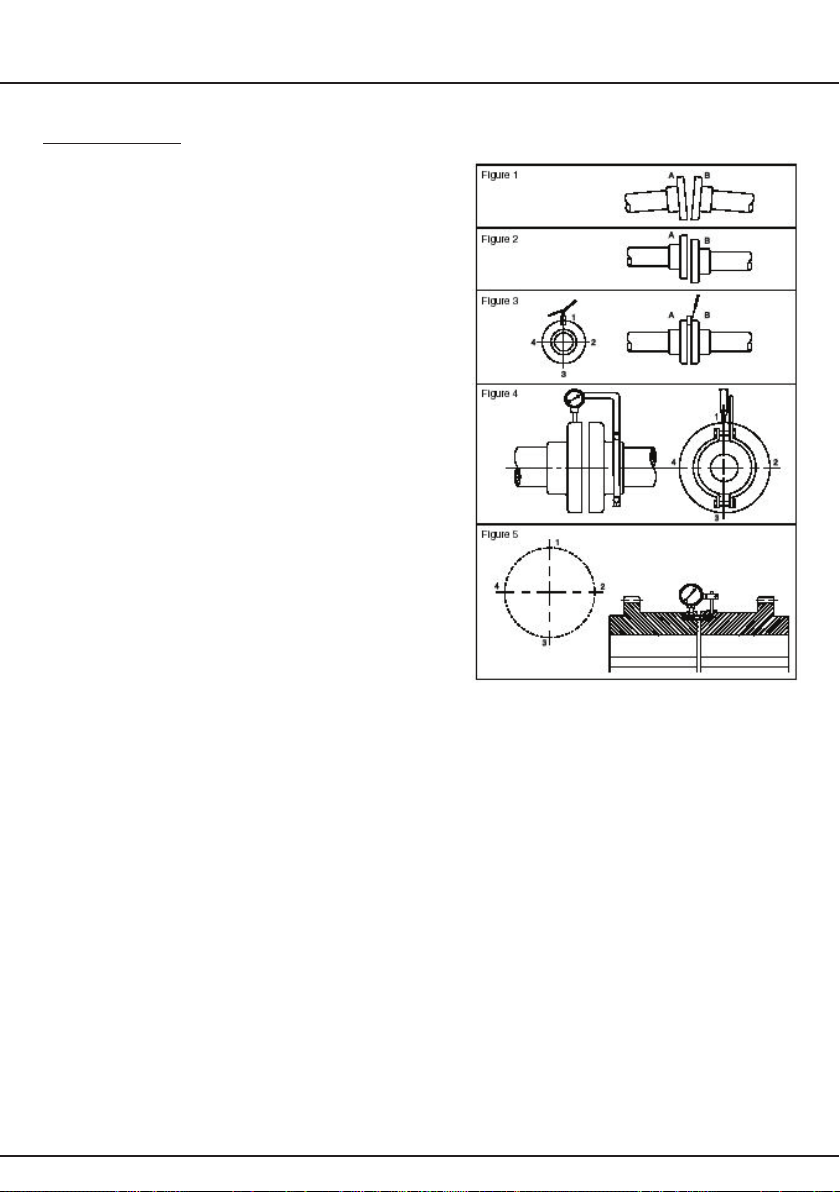
Errors of alignment fall into categories of angularity (See Figure 1)
and eccentricity (see Figure 2), or a combination of both.
Errors of angularity should be checked for, and corrected, before
errors of eccentricity.
Alignment in accordance with the following procedure will ensure
vibration levels meeting those set out in ISO 10816 Part 1
Errors of Angularity
If the faces are perfectly true, the angularity can be checked by
keeping both shafts stationary and taking measurements with a
block gauge and feelers at the four points 1, 2, 3 and 4 as shown
in Figure 3. The difference between the readings 1 and 3 will give
the error of alignment in the vertical plane, over the length of the
shaftequaltothediameterofthecouplinganges,andfromthis
the difference in the relative heights of the feet of the motor or
other connected machine can be found by proportion. Similarly,
the difference between the reading 2 and 4 gives the amount of
sideways adjustment necessary to correct any errors of alignment
in the horizontal plane.
Generally, however, the coupling faces will not be absolutely true
and whilst any errors so found, could be allowed for in checking
angularity by the stationary method an easier method presents
itself. This consists in making the points 1 on both “A” and “B” and
rotating both half couplings, keeping the marked points together.
By taking measurements each quarter-revolution the errors in the
vertical and horizontal planes are again found.
NOTE! Check the alignment after running the unit until it has
attained its normal working temperature. Any discrepancies can
thenberectied.
19
APPENDIX 1
Type of Coupling Allowable Gap (G)
(mm)
Rigid Coupling G = 0.0005 D
All other types Please see appropriate Installation and
MaintenanceManualforcouplingtypetted.
The permitted angularity error is as follows:
Table 5
Note! D is the diameter (mm) at which the gap is measured.
Errors of Eccentricity
The procedure for measuring eccentricity is precisely analogous to that used for angularity. In this case, however, the
measurements are taken in a radial direction and the most convenient and accurate means of doing this utilises a dial
indicatorsuitablyclampedtoonehalfcoupling,andbearingonthehuborangeoftheother,asshowninFigure4
and Figure 5 on Page 22.
Carehowevermustbetakentoensurethesupportforthedialindicatorissufcientlyrigidtopreventtheweightofthe
indicatorfromcausingdeectionand,inconsequence,inaccuratereadings.Extracareshouldbetakenwheretaper
rollerbearingsarettedtoensurethatalignmentischeckedwithshaftsinmid-pointpositionandanalcheckmade
with the unit at operating temperature.
The permitted eccentricity error which can be accommodated in addition to that of the angularity error is as follows:
Table 6
SPECIAL NOTE CONCERNING RIGID COUPLINGS
In lining up elements involving rigid couplings it is important that no attempt is made to correct errors of alignment or
eccentricity greater than those above by tightening of the coupling bolts. (This applies when the system is cold or at
operating temperature). The result is misalignment and the setting up of undue stresses in the shaft, coupling and
bearings. This will be revealed by the springing apart of the coupling faces if the bolts are slackened off. A check on the
angularity of a pre-assembled job, after bolting down, can be obtained in the case of rigid couplings by slackening off
the coupling bolts, when any misalignment will cause the coupling faces to spring apart. This check may not, however,
reveal any strains due to eccentricity owing to the constraint restrain imposed by the spigot.
Type of Coupling Allowable Eccentricity
(mm)
Rigid Coupling 0.025
All other types Please see appropriate Installation and
MaintenanceManualforcouplingtypetted.
20
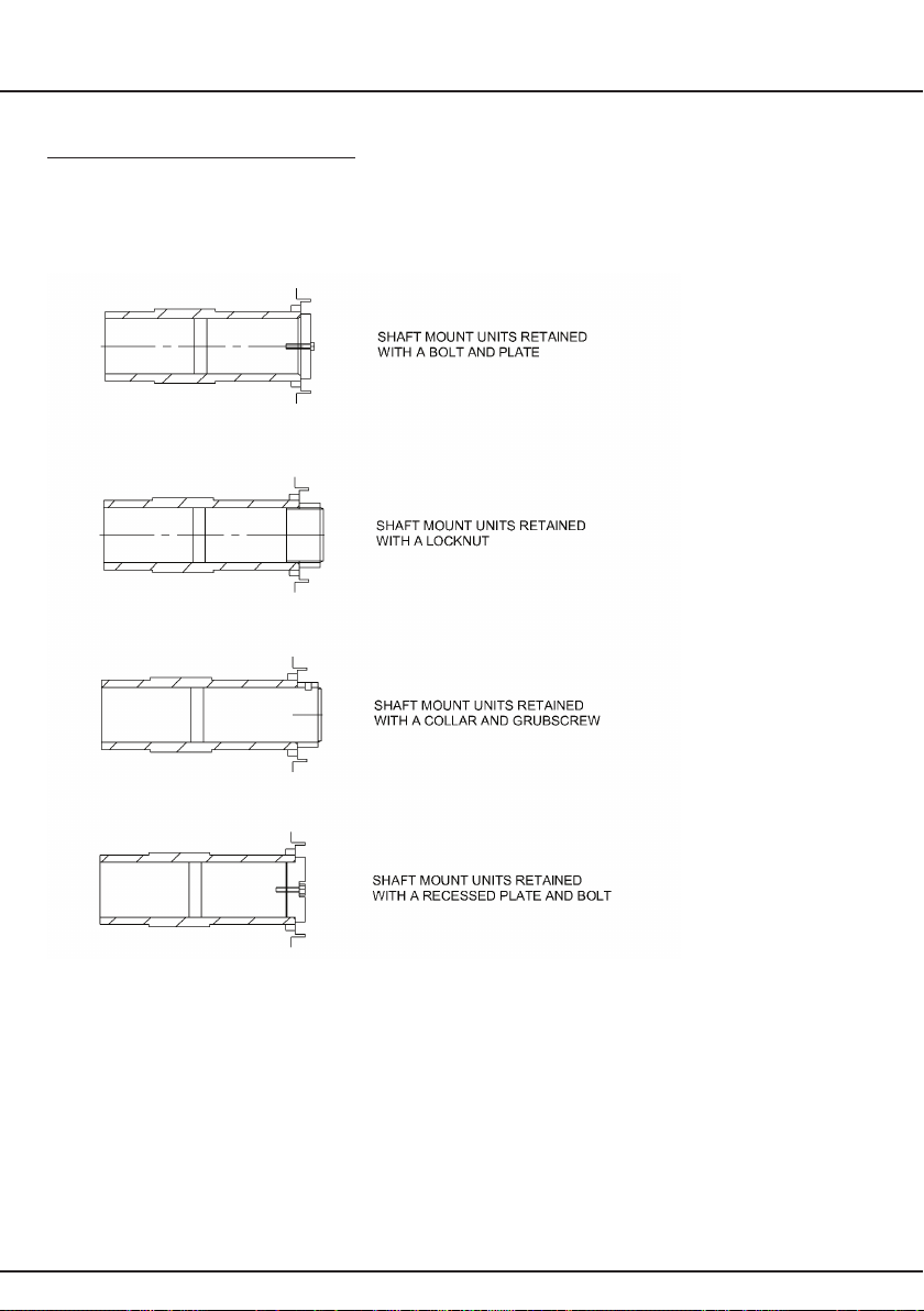
APPENDIX 2
Alternative Shaft Fixing Methods
This manual suits for next models
4
Table of contents
Other Benzlers Industrial Equipment manuals


