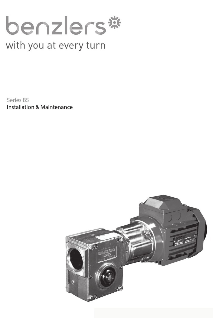
Benzlers M Series Maintenance and service guide

INSTALLATION &
MAINTENANCE
Series M. C. F. K.
IGM1.00GBA0707
Series MCFK Cover:English Cover (Series F) 06.07 17/7/07 16:54 Page 2

3URGXFW6DIHW\
,03257$17
3URGXFW6DIHW\,QIRUPDWLRQ
*HQHUDO7KHIROORZLQJLQIRUPDWLRQLVLPSRUWDQWLQHQVXULQJVDIHW\,WPXVWEHEURXJKWWRWKHDWWHQWLRQRISHUVRQQHOLQYROYHGLQWKHVHOHFWLRQRI0&)DQG.
WUDQVPLVVLRQHTXLSPHQWWKRVHUHVSRQVLEOHIRUWKHGHVLJQRIWKHPDFKLQHU\LQZKLFKLWLVWREHLQFRUSRUDWHGDQGWKRVHLQYROYHGLQLWVLQVWDOODWLRQXVHDQG
PDLQWHQDQFH
7KLVHTXLSPHQWZLOORSHUDWHVDIHO\SURYLGHGLWLVVHOHFWHGLQVWDOOHGXVHGDQGPDLQWDLQHGSURSHUO\$VZLWKDQ\SRZHUWUDQVPLVVLRQHTXLSPHQWSURSHU
SUHFDXWLRQVPXVWEHWDNHQDVLQGLFDWHGLQWKHIROORZLQJSDUDJUDSKVWRHQVXUHVDIHW\
3RWHQWLDO+D]DUGVWKHVHDUHQRWQHFHVVDULO\OLVWHGLQDQ\RUGHURIVHYHULW\DVWKHGHJUHHRIGDQJHUYDULHVLQLQGLYLGXDOFLUFXPVWDQFHV,WLVLPSRUWDQWWKHUHIRUH
WKDWWKHOLVWLVVWXGLHGLQLWVHQWLUHW\
)LUH([SORVLRQ
D 2LOPLVWVDQGYDSRXUDUHJHQHUDWHGZLWKLQJHDUXQLWV,WLVWKHUHIRUHGDQJHURXVWRXVHQDNHGOLJKWVLQWKHSUR[LPLW\
RIJHDUER[RSHQLQJV
E ,QWKHHYHQWRIILUHRUVHULRXVRYHUKHDWLQJRYHU&FHUWDLQPDWHULDOVUXEEHUSODVWLFVHWFPD\GHFRPSRVHDULGSURGXFHIXPHV&DUHVKRXOG
EHWDNHQWRDYRLGH[SRVXUHWRWKHIXPHVDQGWKHUHPDLQVRIEXUQHGRURYHUKHDWHGSODVWLFUXEEHUPDWHULDOVVKRXOGEHKDQGOHGZLWKUXEEHUJORYHV
F ,IFRUUHFWO\LQVWDOOHGDQGRSHUDWHGWKHHTXLSPHQWFRPSOLHVWR(&$7(;DDVPDUNHGRQWKHQDPHSODWH)DLOXUHWRFRPSO\FRXOGOHDGWR
VHYHUHRUIDWDOLQMXU\
*XDUGV5RWDWLQJVKDIWVDQGFRXSOLQJVPXVWJXDUGHGWRHOLPLQDWHWKHSRVVLELOLW\RISK\VLFDOFRQWDFWRUHQWDQJOHPHQWRIFORWKLQJ,WVKRXOGEHRIULJLG
FRQVWUXFWLRQDQGILUPO\VHFXUHG
1RLVH+LJKVSHHGJHDUER[HVDQGJHDUER[GULYHQPDFKLQHU\PD\SURGXFHQRLVHOHYHOVZKLFKDUHGDPDJLQJWRWKHKHDULQJZLWKSURORQJHGH[SRVXUH(DU
GHIHQGHUVVKRXOGEHSURYLGHGIRUSHUVRQQHOLQWKHVHFLUFXPVWDQFHV5HIHUHQFHVKRXOGEHPDGHWRWKH'HSDUWPHQWRI(PSOR\PHQW&RGHRI3UDFWLFHIRU
UHGXFLQJH[SRVXUHRIHPSOR\HGSHUVRQVWRQRLVH
/LIWLQJ :KHUHSURYLGHGRQODUJHUXQLWVRQO\WKHOLIWLQJSRLQWVRUH\HEROWVPXVWEHXVHGIRUOLIWLQJRSHUDWLRQVVHHPDLQWHQDQFHPDQXDORUJHQHUDO
DUUDQJHPHQWGUDZLQJIRUOLIWLQJSRLQWSRVLWLRQV)DLOXUHWRXVHWKHOLIWLQJSRLQWVSURYLGHGPD\UHVXOWLQSHUVRQDOLQMXU\DQGRUGDPDJHWRWKHSURGXFWRU
VXUURXQGLQJHTXLSPHQW.HHSFOHDURIUDLVHGHTXLSPHQW
/XEULFDQWVDQG/XEULFDWLRQ
D 3URORQJHGFRQWDFWZLWKOXEULFDQWVFDQEHGHWULPHQWDOWRWKHVNLQ7KHPDQXIDFWXUHUVLQVWUXFWLRQVPXVWEHIROORZHGZKHQKDQGOLQJOXEULFDQWV
E 7KHOXEULFDWLRQVWDWXVRIWKHHTXLSPHQWPXVWEHFKHFNHGEHIRUHFRPPLVVLRQLQJ5HDGDQGFDUU\RXWDOOLQVWUXFWLRQVRQWKHOXEULFDQWSODWHDQGLQWKH
LQVWDOODWLRQDQGPDLQWHQDQFHOLWHUDWXUH+HHGDOOZDUQLQJWDJV)DLOXUHWRGRVRFRXOGUHVXOWLQPHFKDQLFDOGDPDJHDQGLQH[WUHPHFDVHVULVNRI
LQMXU\WRSHUVRQQHO
(OHFWULFDO(TXLSPHQW2EVHUYHKD]DUGZDUQLQJVRQHOHFWULFDOHTXLSPHQWDQGLVRODWHSRZHUEHIRUHZRUNLQJRQWKHJHDUER[RUDVVRFLDWHGHTXLSPHQWLQ
RUGHUWRSUHYHQWWKHPDFKLQHU\EHLQJVWDUWHG
,QVWDOODWLRQ0DLQWHQDQFHDQG6WRUDJH
D ,QWKHHYHQWWKDWHTXLSPHQWLVWREHKHOGLQVWRUDJHIRUDSHULRGH[FHHGLQJPRQWKVSULRUWRLQVWDOODWLRQRUFRPPLVVLRQLQJORFDODSSOLFDWLRQ
HQJLQHHULQJVWDIIPXVWEHFRQVXOWHGUHJDUGLQJVSHFLDOSUHVHUYDWLRQUHTXLUHPHQWV8QOHVVRWKHUZLVHDJUHHGHTXLSPHQWPXVWEHVWRUHGLQDEXLOGLQJ
SURWHFWHGIURPH[WUHPHVRIWHPSHUDWXUHDQGKXPLGLW\WRSUHYHQWGHWHULRUDWLRQ
7KHURWDWLQJFRPSRQHQWVJHDUVDQGVKDIWVPXVWEHIXPHGDIHZUHYROXWLRQVRQFHDPRQWKWRSUHYHQWEHDULQJVEULQHOOLQJ
E ([WHUQDOJHDUER[FRPSRQHQWVPD\ EHVXSSOLHGZLWKSUHVHUYDWLYHPDWHULDOVDSSOLHGLQWKHIRUPRIDZD[HGWDSHRYHUZUDSRUZD[ILOPSUHVHUYDWLYH
*ORYHVVKRXOGEHZRUQZKHQUHPRYLQJWKHVHPDWHULDOV7KHIRUPHUFDQEHUHPRYHGPDQXDOO\WKHODWWHUXVLQJZKLWHVSLULWDVDVROYHQW
3UHVHUYDWLYHVDSSOLHGWRWKHLQWHUQDOSDUWVRIWKHJHDUXQLWVGRQRWUHTXLUHUHPRYDOSULRUWRRSHUDWLRQ
F ,QVWDOODWLRQPXVWEHSHUIRUPHGLQDFFRUGDQFHZLWKWKHPDQXIDFWXUHUVLQVWUXFWLRQVDQGEHXQGHUWDNHQE\VXLWDEO\TXDOLILHGSHUVRQQHO
G %HIRUHZRUNLQJRQDJHDUER[ RUDVVRFLDWHGHTXLSPHQWHQVXUHWKDWWKHORDGKDVEHHQUHPRYHGIURPWKHV\VWHPWRHOLPLQDWHWKHSRVVLELOLW\RIDQ\
PRYHPHQWRIWKHPDFKLQHU\DQGLVRODWHSRZHUVXSSO\:KHUHQHFHVVDU\SURYLGHPHFKDQLFDOPHDQVWRHQVXUHWKHPDFKLQHU\FDQQRWPRYHRU
URWDWH(QVXUHUHPRYDORIVXFKGHYLFHVDIWHUZRUNLVFRPSOHWH
H (QVXUHWKHSURSHUPDLQWHQDQFHRIJHDUER[HVLQRSHUDWLRQ8VHRQO\WKHFRUUHFWWRROVDQGDSSURYHGVSDUHSDUWVIRUUHSDLUDQGPDLQWHQDQFH
&RQVXOWWKH0DLQWHQDQFH0DQXDOEHIRUHGLVPDQWOLQJRUSHUIRUPLQJPDLQWHQDQFHZRUN
+RW6XUIDFHVDQG/XEULFDQWV
D 'XULQJRSHUDWLRQJHDUXQLWVPD\EHFRPHVXIILFLHQWO\KRWWRFDXVHVNLQEXUQV&DUHPXVWEHWDNHQWRDYRLGDFFLGHQWDOFRQWDFW
E $IWHUH[WHQGHGUXQQLQJWKHOXEULFDQWLQJHDUXQLWVDQGOXEULFDWLRQV\VWHPVPD\UHDFKWHPSHUDWXUHVVXIILFLHQWWRFDXVHEXPV$OORZHTXLSPHQWWR
FRROEHIRUHVHUYLFLQJRUSHUIRUPLQJDGMXVWPHQWV
6HOHFWLRQDQG'HVLJQ
D :KHUHJHDUXQLWVSURYLGHDEDFNVWRSIDFLOLW\HQVXUHWKDWEDFNXSV\VWHPVDUHSURYLGHGLIIDLOXUHRIWKHEDFNVWRSGHYLFHZRXOGHQGDQJHUSHUVRQQHO
RUUHVXOWLQGDPDJH
E 7KHGULYLQJDQGGULYHQHTXLSPHQWPXVWEHFRUUHFWO\VHOHFWHGWRHQVXUHWKDWWKHFRPSOHWHPDFKLQHU\LQVWDOODWLRQZLOOSHUIRUPVDWLVIDFWRULO\DYRLGLQJ
V\VWHPFULWLFDOVSHHGVV\VWHPWRUVLRQDOYLEUDWLRQHWF
F 7KHHTXLSPHQWPXVWQRWEHRSHUDWHGLQDQHQYLURQPHQWRUDWVSHHGVSRZHUVWRUTXHVRUZLWKH[WHUQDOORDGVEH\RQGWKRVHIRUZKLFKLWZDV
GHVLJQHG
G $VLPSURYHPHQWVLQGHVLJQDUHEHLQJPDGHFRQWLQXDOO\WKHFRQWHQWVRIWKLVFDWDORJXHDUHQRWWREHUHJDUGHGDVELQGLQJLQGHWDLODQGGUDZLQJVDQG
FDSDFLWLHVDUHVXEMHFWWRDOWHUDWLRQVZLWKRXWQRWLFH
7KHDERYHJXLGDQFHLVEDVHGRQWKHFXUUHQWVWDWHRINQRZOHGJHDQGRXUEHVWDVVHVVPHQWRIWKHSRWHQWLDOKD]DUGVLQWKHRSHUDWLRQRIWKHJHDUXQLWV
$Q\IXUWKHULQIRUPDWLRQRUFODULILFDWLRQUHTXLUHGPD\EHREWDLQHGE\FRQWDFWLQJ\RXUORFDODSSOLFDWLRQHQJLQHHULQJRIILFH
Series MCFK Cover:English Cover (Series F) 06.07 2/7/07 11:06 Page 3

Information
Page 1 Issue 2
Section Description Page No
1GeneralInformation 2
2 Weather Protection 2
3 Reading The Nameplate 2
4 Marking 3
5 Installation
5.1SafetyWarning 4
5.2 Prior to Installation 4
5.3 Fitting Components to Input or Output Shafts 4
5.4Lifting 5
5.5 Installing Foot or Flange mount units 6
5.6 Installing Shaft Mount Units 7
5.7 Units for use in a potentially explosive atmosphere 7
6 Lubrication
6.1General 8
6.2Ventilator 8
6.3OilLevel 8
7 Motor Connections 9
8 StartingUp 9
9 Operation
9.1Noise 9
9.2GeneralSafety 9
9.3 Units for use in a potentially explosive atmosphere 9
10 Maintenance
10.1 Prior to any Maintenance Operations 10
10.2 Oil Plugs & Ventilator 10
10.3 Lubrication 11
10.4 Bearings 11
10.5 Grease Lubrication 11
10.6 Cleaning 11
11 Fault Diagnosis 12
Appendix
1 Shaft Alignment 13-14
2A Series C, F & K Hollow Output Bore Details 15-18
2B Series F Kibo Bush Details 19-20
2C Series K Shrink Disc Details 21-22
2D Series C, F & K Torque Arm Details 23 - 25
3 Three Phase Induction Motor Installation 26
4 Lubrication Information 27-37
Safety warning Symbols
Electrical Hazard
Could result in death or
serious injury
Danger
Could result in serious, slight
or minor injuries
Danger (Touch Hazard)
Could result in death or
serious injury
Damaging Situation
Could result in damage to
gear unit or driven machinery
Important notes on Explosion
Protection
Cleaning
Periodic cleaning necessary

Information
Page 2 Issue 2
1. General Information
The following instructions will help you achieve a satisfactory installation of your gear unit, ensuring the
best possible conditions for a long and trouble free operation.
All units are tested and checked prior to despatch, a great deal of care is taken in packing and shipping
arrangements to ensure that the unit arrives at the customer in the approved condition.
2. Weather Protection of Unit
All Series M C F & K units are provided with protection against normal weather conditions. Where units are
to operate in extreme conditions, or where they are to stand for long periods without running, eg during
plant construction, consult our application engineers so that arrangements for adequate protection can be
made.
3. Reading the Nameplate
Unit Identification
When requesting further information, or service support quote the
following information from the nameplate:
• Unit type (Model No)
• Order Number / Year of Manufacture
Lubrication Grade
The grade is marked on the nameplate. See Appendix 4 for type and quantity of lubricant.

Information
Page 3 Issue 2
4. Marking
These gear units are intended for use in industrial systems.
Provided they are correctly selected marked and installed in accordance with these instructions (gear
units only) they comply with the EU directive 94/9/EC ATEX 100a Group II Cat 2 zones 1 & 21 & Cat 3
zones 2 & 22.
Motors, couplings, or any other equipment fitted to the gear unit must also comply with this directive.
If the gear unit is supplied as a geared motor package it is important to check the nameplates of the gear
unit and the motor (or any other equipment fitted) corresponds with the classification of the potentially
explosive atmosphere in which the unit is to be installed.
Understanding EU Directive 94/9/EC (ATEX 100a) Markings.
II 2 G EEx c,k, T4
Temp classTemp class
Ex-Atmosphere
Category
Group
T3 Max. surface temperature 200°C
T4 Max. surface temperature 135°C
T5 Max. surface temperature 100°C
Protection type of gear unit
G = Gas
D = Dust
Examples:
II 2 G - (Zone 1) occasional hazardous explosive atmosphere
II 3 G - (Zone 2) rare short-term hazardous explosive atmosphere
II 2 D - (Zone 21) occasional hazardous explosive atmosphere during normal
operation due to presence of combustible dust
II 3 D - (Zone 22) short-term hazardous explosive atmosphere due to presence
of combustible dust; no hazard during normal operation

Installation
Page 4 Issue 2
5. Installation
5.1. Safety Warning
WARNING! The customer shall be responsible for the proper use of articles supplied by
the company, particularly the rotating shafts between their driving and driven members,
and their guarding for safety, and the company shall not be responsible for any injury or
damage sustained as a result of the improper use of the articles supplied.
Attention is hereby drawn to the danger of using naked lights in proximity to openings in
gearboxes and gear units supplied by the company, and the company shall not be liable
for any claim for injury or damage arising from any action in contravention of this warning.
5.2. Prior to Installation
5.2.1. Check gear unit has not been damaged.
5.2.2. Check the gear unit / motor nameplate matches the requirements of the machine the unit is to be
installed into.
5.2.3. Thoroughly clean the shaft and mounting surfaces that are to be used of anti-corrosion agents using
a commercially available solvent. Ensure solvent does not make contact with the oil seals.
5.3. Fitting of components to either the unit input or output shaft
The input or output shaft extension diameter tolerance is to ISO tolerance k6 (for shaft diameter ≤
50mm) and m6 (for shaft diameter > 50mm) and the fitted components should be to ISO tolerance
M7 (for bore diameter ≤50mm) and K7 (for bore diameter > 50mm).
5.3.1. Ensure shaft extensions, bores & keys etc are cleaned.
5.3.2. Items (such as gears, sprockets, couplings etc) should not be hammered onto these shafts since
this would damage the shaft support bearings.
5.3.3. The item should be pushed onto the shaft using a screw jack device fitted into the threaded hole
provided in the end of the shaft. See table 1 below.
5.3.4. Items being fitted may be heated to 80/100°C to aid assembly further.
Over To
13 16
16 21
21 24
24 30
30 38
38 50
50 85
85 130
Shaft Diameter Threaded Hole Details
M5 x 0.8 12 deep
M6 x 1.0 16 deep
M24 x 3.0 55 deep
M8 x 1.25 19 deep
M10 x 1.5 22 deep
M12 x 1.75 28 deep
M20 x 2.5 42 deep
M16 x 2.0 36 deep
Table 1

Installation
Page 5 Issue 2
5.4. Lifting
Use only lifting points provided.
Larger Series M & C units are supplied with a lifting eye.
Series F & K units, have a lifting hole in the gear housing as shown.
Lifting Hole
Series K
Lifting Hole
Series F
On units supplied with a lifting eye on the motor, both the lifting point on the gear unit and motor
should be used.
Use both lifting points

Installation
Page 6 Issue 2
5.5. Foot mounted or flange mounted units
5.5.1. Ensure the base foundation / flange mounting surface is flat¹, vibration absorbing and torsionally
rigid.
5.5.2. The gear unit must be installed in the specified mounting position. The maximum deviation from the
designated mounting position is ± 5° (unless gear unit is suitably modified and approved for non
standard mounting positions).
5.5.3. Align unit (see Appendix 1).
Note: It is important to ensure when aligning unit on baseplate that all machined mounting
points are supported over their full area.
If steel packings are used, these should be placed either side of the foundation bolt as close
as possible.
During final bolting ensure the unit or baseplate is not distorted as this would cause strains in
the gear case resulting in errors of alignment of shafts and gearing.
Check all mounting points are fully supported and adjust if necessary by using steel
packings.
Torque tighten bolts to torque specified in table 2 below.
5.5.4. Secure unit, or baseplate if fitted to a rigid foundation using heavy duty bolts to ISO grade 8.8
minimum
-
-
M30
M36
1220 Nm
2150 Nm
350 Nm
610 Nm
10 Nm
18 Nm
37 Nm
64 Nm
150 Nm
260 Nm
-
25 Nm
50 Nm
85 Nm
200 Nm
Tightening Torque
Holding Down Bolts /
Output Flange Bolts Motors to Gearhead
10 Nm
M12
M16
M20
M24
Set Screw
Size
M6
M8
M10
Table 2
5.5.5. Recommended fasteners (Basemount units):
Unit Size Unit Size Unit Size
M01 K03 C03
M02 K04 C04
M03 K05 C05
M04 K06 C06
M05 K07 C07
M06 K08 C08
M07 K09 C09
M08 K10 C10
M09 K12
M10
M13
M14
M36 x 100L
Recommended Fastener Size
M8 x 20L
M10 x 30L
M10 x 30L
M12 x 40L
M16 x 50L
M20 x 65L
M24 x 75L
M24 x 80L
M36 x 100L
Recommended Fastener Size
M10 x 25L
M10 x 30L
M12 x 35L
M12 x 40L
M16 x 50L
M20 x 60L
M24 x 70L
M30 x 80LM16 x 60L
M20 x 70L
M24 x 80L
M30 x 90L
M12 x 40L
M12 x 40L
M12 x 40L
M16 x 45L
Recommended Fastener Size
M8 x 25L
M8 x 30L
M8 x 30L
Table 3
¹ Maximum permissible flatness error for mounting surface is 0.12mm.

Installation
Page 7 Issue 2
5.6. Shaft mounted units
5.6.1. The gear unit must be installed in the specified mounting position.
5.6.2. Assembly of gear unit on to the machine shaft:
There are four assembly methods dependant on the gear unit type:
• Standard straight bore with keyway. See Appendix 2A.
• Unit fitted with KIBO® bushes. See Appendix 2B.
• Unit fitted with shrink disc. See Appendix 2C.
5.6.3. Anchor gear unit to a secure point on the structure by means of a torque arm. (See Appendix 2E)
5.7. Units for use in a potentially explosive atmosphere
5.7.1. If the unit has been damaged in transit do not use. (Remove all transport fixtures and packings prior
to start up)
5.7.2. Check nameplate of unit corresponds with the sites potentially explosive atmosphere classification.
5.7.3. Check ambient temperature falls within lubricant grade recommendations. (See Approved
Lubricants p27)
5.7.4. Make sure no potentially explosive atmosphere exists during installation.
5.7.5. Make sure that gear unit is sufficiently ventilated with no external heat input – cooling air
temperature should not exceed 40°C
5.7.6. Ensure mounting position corresponds to that marked on the nameplate. (Note! ATEX approval is
only valid for mounting position specified on the nameplate.)
5.7.7. Check motors, couplings or any other equipment fitted to the gear unit has ATEX approval.
Check information listed on nameplates correspond to the environmental conditions of the site.
5.7.8. Ensure gearbox is not subjected to any loading greater than those marked on the nameplate.
5.7.9. For units operated with inverter drives, check motor suitability for use with the inverter.
Ensure that the inverter parameters do not exceed those of the motor.
5.7.10. For belt driven units, check all belts fitted are of sufficient electrical leakage resistance. (< 109Ω).
5.7.11. Ensure gear unit and other equipment is electrically grounded (Earthed).
5.7.12. Check and adjust guards and covers so that there is no ignition source from sparks that may be
thrown by moving parts making contact with guards etc. Ensure coupling guards, covers etc are
dust tight or are designed in such a way that a build up of dust deposits cannot form when the unit
is used in Zone 21 & Zone 22 classification areas.

Lubrication
Page 8 Issue 2
6. Lubrication
6.1. General
6.1.1. Series M F & K size 7 and below will be supplied factory filled with a quantity of EP mineral oil
(Grade 6E) appropriate to the intended mounting position. However if, as requested, the gear unit is
supplied without lubricant then the oil quantity required is obtained from Appendix 4. Gear units size
8 and larger are supplied without lubricant (unless factory filled by request). Recommended
lubricants are listed in our Approved Lubricants pages in Appendix 4.
6.1.2. Series C size 6 and below are supplied factory filled with synthetic lubricant (Grade 6G). Size 7 and
larger are supplied without lubricant.
Temperature Limitations
The standard lubricant is suitable for operation in ambient temperatures of 0° to 35°C. Outside of this
consult Table L1 or Application Engineers.
6G (VG 320) 7G (VG 460)
Polyglycol
based S
y
nthetic
(type G)
Polyalphaolefin
based S
y
nthetic
with EP additive
(type H)
CLP (PG) 5G (VG 220)
Ambient Temperature Range
Lubricant(ISO)
EP Mineral Oil
(type E)
CLP (CC) 5E (VG 220) 6E (VG 320) 7E (VG 460)
-5°C to 20°C (type E)
-30°C to 20°C (type G & H) 0°C to 35°C 20°C to 50°C
CLP (HC) 5H (VG 220) 5H (VG 220) 6H (VG 320)
Table L1
Note! CLP (CC) & CLP (HC) are the recommended lubricants for Series F K & M.
6.2. Ventilator
6.2.1. Clean & secure the ventilator (if supplied) in the correct location for the required mounting position.
(See Appendix 4)
6.3. Oil Level:
Units supplied without oil:
6.3.1. Fill gear unit with correct type of lubricant until oil escapes from level plug. See Appendix 4
Factory filled units:
6.3.2. If the unit is fitted with a level plug, (See Appendix 4) check oil level and top up with correct oil type
as necessary.
WARNING Do not overfill as excess may cause overheating and leakage.
6.3.3. Re-fit plugs & tighten to correct torque figure – see notes in maintenance section. Clean away any
oil spillage from the surface of the gear unit and driven machinery.

Start Up
Page 9 Issue 2
7. Motor Connections
To mains:
7.1. Connection of the electric motor to the mains supply should be made by a qualified person. The current
rating of the motor will be identified on the motor plate, and correct sizing of the cables to electrical
regulations is essential.
Motor terminal connection:
7.2. Circuit diagrams for the correct wiring of the motor terminal box are included as Appendix 3 of this
document if the motor is fitted with our ‘own brand’ motor.
Alternatively if the motor is supplied separately or if fitted with a motor from a different manufacturer,
then this should have appropriate documentation provided with it.
8. Starting Up
8.1. Prior to starting up
8.1.1. Ensure ventilator is fitted (if supplied) see lubrication section 6.2
8.1.2. Check oil level, top up if necessary.
8.1.3. Ensure all safety devices are in place (ie guards fitted). Check and adjust guards and covers so that
there is no ignition source from sparks that may be thrown by moving parts making contact with
guards etc. Ensure coupling guards, covers etc are dust tight or are designed in such a way that a
build up of dust deposits cannot form when the unit is used in Zone 21 & Zone 22 classification
areas.
8.1.4. Remove any safety devices fitted to prevent machine rotation.
8.1.5. Starting up should only be performed or supervised by suitably qualified personnel.
Caution: Any deviation from normal operating conditions, (increased temperature, noise,
vibrations, power consumption etc) suggest a malfunction, inform maintenance personnel
immediately.
8.1.6. Units fitted with backstop, ensure motor is correctly wired for free direction of rotation.
9. Operation
9.1. Noise
The range of product satisfies a noise (sound pressure level) of 85dB(A) or less when measured at 1
metre from the unit surface.
Measurements taken in accordance with B.S.7676 Pt1 : 1993 (ISO 8579-1 : 1993).
9.2. General Safety
Potential hazards which can be encountered during installation, maintenance and operation of drives
is covered in greater detail in the product safety page at the front of this booklet.
Advice is also given on sensible precautions which need to be taken to avoid injury or damage.
PLEASE READ!
9.3. Gear units for use in a potentially explosive atmosphere
After 3 hours of operation check the gear unit surface temperature. This temperature should not
exceed 110°C. If temperature exceeds this limit, shut down immediately and contact your local sales
office.

Maintenance
Page 10 Issue 2
10. Maintenance
10.1. Prior to any maintenance operations
10.1.1. De-energise the drive and secure against un-intentional switch on.
10.1.2.Wait until the unit has cooled down – Danger of skin burns & pressure build up.
10.2. Oil plugs/ventilator
10.2.1. Prior to removing plugs, ensure that the unit has cooled sufficiently so that oil will not burn.
10.2.2. Remove ventilator plug prior to removing level and/or drain plug. Warning do not stand over
ventilator plug whilst removing as pressure build up behind valved ventilator may cause it to eject
when removed.
10.2.3. Place a container under the oil drain plug to be removed. Note: it is recommended that the oil
should be slightly warm, (40-50°C) when drained. (Cooler oil will be more difficult to drain correctly).
10.2.4. Top ups or refills should be done through the ventilator position.
10.2.5.Remember to refit all plugs and torque tighten to table M1 below.
M10 12Nm
M12 20Nm
M14 26Nm
M16 34Nm
M22 65Nm
Plug Size Tightening
Tor
q
ue
Table M1
10.2.6. Clean away any oil spillage.

Maintenance
Page 11 Issue 2
10.3. Lubrication
10.3.1. Periodic inspection.
For Units fitted with level plug or other level indicating device, check the oil level every 3000 hours
or 6 months whichever is sooner and if necessary top up with the recommended type of lubricant.
10.3.2. Oil changes.
• Smaller units (supplied without ventilator) are supplied lubricated for life* except for the
following conditions:
Units that are required to work in explosive atmosphere (94/9/EC Atex 100a Group II category
2 zones 1 & 21 & category 3 zones 2 & 22) should be drained and refilled with correct quantity
of lubricant in accordance with the schedule as listed on the tables below. See Appendix 4 for
correct oil quantity.
• Larger units (supplied with ventilator) should be drained and refilled with correct quantity of
lubricant in accordance with the tables below. See Appendix 4 for correct oil quantity.
Oil Change Period: Series F K & M
MINERAL OIL SYNTHETIC OIL
75 OR LESS 17000 HOURS OR 3 YEARS 26000 HOURS OR 3 YEARS
80 12000 HOURS OR 3 YEARS 26000 HOURS OR 3 YEARS
85 8500 HOURS OR 3 YEARS 21000 HOURS OR 3 YEARS
90 6000 HOURS OR 2 YEARS 15000 HOURS OR 3 YEARS
95 4200 HOURS OR 17 MONTHS 10500 HOURS OR 3 YEARS
100 3000 HOURS OR 12 MONTHS 7500 HOURS OR 2 1/2 YEARS
105 2100 HOURS OR 8 MONTHS 6200 HOURS OR 2 YEARS
110 1500 HOURS OR 6 MONTHS 2100 HOURS OR 18 MONTHS
Oil Change Period: Series C
MINERAL OIL SYNTHETIC OIL
65 OR LESS 17000 HOURS OR 3 YEARS 26000 HOURS OR 3 YEARS
70 12000 HOURS OR 3 YEARS 26000 HOURS OR 3 YEARS
75 8500 HOURS OR 3 YEARS 22000 HOURS OR 3 YEARS
80 6000 HOURS OR 2 YEARS 15000 HOURS OR 3 YEARS
85 4200 HOURS OR 17 MONTHS 10500 HOURS OR 3 YEARS
90 3000 HOURS OR 12 MONTHS 7500 HOURS OR 2 1/2 YEARS
95 2100 HOURS OR 8 MONTHS 6000 HOURS OR 2 YEARS
100 1500 HOURS OR 6 MONTHS 4500 HOURS OR 18 MONTHS
UNIT OPERATING
TEMPERATURE °C
RENEWAL PERIOD
NB: INITIAL FILL OF OIL SHOULD BE CHANGED IN A NEW GEAR UNIT AFTER 1000 HOURS
OPERATION OR ONE YEAR OR HALF THE ABOVE LIFE WHICHEVER IS THE SOONEST
UNIT OPERATING
TEMPERATURE °C
RENEWAL PERIOD
NB: INITIAL FILL OF OIL SHOULD BE CHANGED IN A NEW GEAR UNIT AFTER 1000 HOURS
OPERATION OR ONE YEAR OR HALF THE ABOVE LIFE WHICHEVER IS THE SOONEST
*Mineral oil filled units operating over 70°C should be removed, drained and refilled with the correct
quantity of oil after 3 years operation.
Warning.
Do not mix Synthetic and Mineral lubricants.
Do not overfill the unit as this can cause leakage and overheating.
10.4. Bearings
10.4.1 Bearings should be replaced every 5 years for . marked units.
10.5. Grease Lubrication
10.5.1. Where re-greasing points are provided add 2 shots monthly of NLGI 2 grade grease.
10.6. Cleaning
10.6.1. With the drive stationary periodically clean any dirt or dust from the gear unit and the electric motor
cooling fins and fan guard to aid cooling.
10.6.2. Ensure dust build up does not exceed 5mm (maximum)

Problem Solving
Page 12 Issue 2
11. Fault diagnosis
11.1. Gear unit problems:
Symptom Possible Causes Remedy
Output shaft does not rotate, Drive between shafts interupted in the gear unit Return the gear unit / geared motor for repair
even though the motor is running
or the input shaft is rotating.
Unusual, regular running noise a) A meshing or grinding sound : damage to bearings a) Check oil (See Inspection and Maintenance)
b) A knocking sound : irregularity in the gearing b) Contact our Application Engineers
Unusual, irregular running noise Foreign matter present in the oil a) Check oil (See Inspection and Maintenance)
b) Stop the unit, Contact our Application Engineers
Oil leaking¹ a) Defective gasket on gear unit cover a) Retighten screws on gear unit cover and observe gear
• from the gear unit cover b) Defective gasket unit. If oil still leaks contact our Application Engineers
• from the motor flange c) Gear unit not ventilated b) Contact our Application Engineers
• from the gear unit flange c) Vent the gear unit (see Appendix 4 - Mounting positions)
• from the output end oilseal
Oil leaking a) Gear unit over filled with oil a) Correct the oil level (see lubrication section)
from the ventilator b) Gear unit installed in an incorrect mounting positon b) Fit the ventilator in the correct position (see Appendix 4 -
c) Frequent cold starts (oil foaming) and/or high Mounting positions) and check oil level (see lubrication)
oil level. c) Check the oil level (see lubrication)
1) it is normal for small amounts of oil/grease to leak out of the oil seal during the running in period (24 hours running time)
When contacting our sales office
Please have the following information available:
• Nameplate data (complete)
• Type and extent of the problem encountered
• The time and the circumstances the problem occurred
• A possible cause
Any further information or clarification required may be obtained by contacting our sales office,
please see contact details at the back of this booklet.

Appendix 1
Page 13 Issue 2

Appendix 1
Page 14 Issue 2
Errors of Eccentricity
The procedure for measuring eccentricity is precisely analogous to that used for angularity.
In this case, however, the measurements are taken in a radical direction and the most
convenient and accurate means of doing this utilises a dial indicator suitably clamped to one
half coupling, and bearing on the hub or flange of the other, as shown in figures 4 and 5 on
page 13.
Care must, however, be taken to ensure the support for the dial indicator is sufficiently rigid
to prevent the weight of the indicator from causing deflection and, in consequence,
inaccurate readings. Extra care should be taken where taper roller bearings are fitted to
ensure that alignment is checked with shafts in mid-point position and a final check made
with the unit at operating temperature.
Rigid
All Other types Please see appropiate installation and maintenance
manual for coupling type fitted
Type of Coupling Unit Size Allowable Eccentricity
(mm)
SIZE 08 & UNDER 0.025
SIZE 09 & OVER 0.035
SPECIAL NOTE CONCERNING RIGID COUPLINGS
In lining up elements involving rigid couplings it is important that no attempt is made to
correct errors of alignment or eccentricity greater than those above by tightening of the
coupling bolts (This applies when the system is cold or at operating temperature). The result
is miss-alignment and the setting up of undue stresses in the shaft, coupling and bearings.
This will be revealed by the springing apart of the coupling faces if the bolts are slackened
off. A check on the angularity of a pre-assembled job, after bolting down, can be obtained in
the case of rigid couplings by slackening off the coupling bolts, when any mis-alignment will
cause the coupling faces to spring apart. This check may not, however, reveal any strains
due to eccentricity owing to the constant restraint imposed by the spigot.
SERIES X COUPLINGS
We produce standard flexible couplings to cover the complete range of gear units, please
contact Application Engineering for details.

Appendix 2A
Page 15 Issue 2
Series C, K & F Standard Bore Assembly.
UNIT Bore d da l l1 l2 l3 l4 l5 m R T u u1
22.000/
21.946
28.000/
27.948
0.6
0.4R
0.6
0.4R
1.2R
0.8R
71.0
70.8
90.0
89.8
53
46
M20 x 2.5
42 deep
M24 x 3.0
50 deep
225.5
225.0
238.5
238.0
3
10
120
150
40
45
79.6
99.6
260
327
C10
Reduced
Std
79.990/
79.971
99.988/
99.966
20.000/
19.948
25.000/
24.948
0.6
0.4R
0.6
0.4R
1.2R
1.2R
62.5
62.3
81.0
80.8
58
58
M20 x 2.5
42 deep
M24 x 3.0
50 deep
177.5
177.0
221.5
221.0
3
3
105
135
35
45
69.6
76.6
227
227
C09
Reduced
Std
69.990/
69.971
89.988/
89.966
18.000/
17.957
20.000/
19.948
0.4
0.25R
0.6
0.4R
1.2R
1.2R
53.0
52.8
62.5
62.3
37
37
M20 x 2.5
42 deep
M20 x 2.5
42 deep
148.5
148.0
177.5
177.0
3
3
91
105
31
35
59.6 183
69.990/
69.971 69.6 183
C08
Reduced
Std
59.990/
59.971
44.5
44.3
14.000/
13.957
0.4
0.25R
M20 x 2.5
42 deep 1.2R 53.0
52.8
18.000/
17.957
0.4
0.25R
35
38
M16 x 2
38 deep 1.2R
130.5
130.0
148.5
148.0
3
3
75
90
25
30
49.6
59.6
153
153
C07
Reduced
Std
49.991/
49.975
59.990/
59.971
0.8R 39.5
39.3
14.000/
13.957
0.4
0.25R
101.5
101.0 331
M16 x 2
36 deep
44.6 125 68 23
0.8R 35.0
34.8
12.000/
11.957
0.4
0.25R
100.5
100.0 331
M16 x 2
36 deep
39.6 125 60 20
C06
Reduced
Std
39.991/
39.975
44.991/
44.975
0.8R 30.0
29.8
10.000/
9.964
0.16
0.25R
77.3
77.0 323
M12 x 1.75
28 deep
34.6 104 53 18
0.8R 26.0
25.8
8.000/
7.964
0.16
0.25R
79.3
79.0 323
M10 x 1.5
22 deep
29.6 104 45 15
C05
Reduced
Std
29.993/
29.980
34.991/
34.975
0.8R 26.0
25.8
8.000/
7.964
0.16
0.25R
0.16
0.25R
29.993/
29.980 29.6 99 45 15 79.3
79.0 326
M10 x 1.5
22 deep
M10 x 1.5
22 deep 0.8R 21.0
20.8
8.000/
7.964
Std
C04
24.993/
24.980 24.6
16.5
16.4
6.000/
5.970
0.16
0.25R
Reduced 99 38 13 79.3
79.0 323
322
M6 x 1.0 16
deep 0.8R82 30 10 61.3
61.0
C03 Std 19.993/
19.980 19.6
F03 & K03 - 29.993/
29.980 29.6 82 45 15 70.3
70.0
26.0
25.8
8.000/
7.964
0.16
0.25R
323
M10 x 1.5
22 deep 0.8R
F04 & K04 - 34.991/
34.975 34.6 109 60 20 90.5
90.0 323
M12 x 1.75
28 deep 0.8R 30.0
29.8
10.000/
9.964
0.16
0.25R
F05 & K05 - 39.991/
39.975 39.6 112 60 20 35.0
34.8
12.000/
11.957
0.4
0.25R
92.5
92.0 330
M16 x 2
36 deep
126 75 25
0.8R
F06 & K06 - 39.991/
39.975 39.6 100.5
100.0 330
M16 x 2
36 deep 0.8R 35.0
34.8
12.000/
11.957
0.4
0.25R
F07 & K07 - 44.991/
44.975 49.6 153 75 25 101.5
101.0
44.5
44.3
14.000/
13.957
0.4
0.25R
330
M16 x 2
36 deep 0.8R
F08 & K08 - 59.990/
59.971 59.6 173 90 30 148.5
148.0 337
M20 x 2.5
42 deep 0.8R 53.0
52.8
18.000/
17.957
0.4
0.25R
F09 & K09 - 69.990/
69.971 69.6 232 105 35 161.5
161.0 338
M20 x 2.5
42 deep 0.8R 62.5
62.3
20.000/
19.948
0.6
0.4R
F10 &K10 - 79.990/
79.971 79.6 275 120 40 188.5
188.0 537
M20 x 2.5
42 deep 0.8R 71.0
70.8
22.000/
21.946
0.6
0.4R
K12 - 99.988/
99.966 99.6 327 150 45 238.5
238.0 10 46 M24 x 3.0
50 deep 0.8R 90.0
89.8
28.000/
27.948
0.6
0.4R
F02 - 24.9931/
24.980 24.6 82 40 13 70.3
70.0
21.0
20.8
8.000 /
7.964
0.16
0.25R
323
M10 x 1.5
22 deep 0.8R
See next page for shaft assembly instructions

Appendix 2A
Page 16 Issue 2
Shaft Assembly Instructions.
1. Spray the hollow shaft bore and mating diameter of output shaft with an anti fret compound.
2. Fit the shaft to hollow bore location key in position in the output shaft.
3. Fit the circlip into the output sleeve.
4. Fit the output shaft into the output sleeve. Remember to fit the spacer tube if the output shaft has
no shoulder.
5. Secure in place with the washer and bolt, tighten to the values stated in the table below.
6. Fit the protective cover over the open end of the output sleeve.
M10 15
M12 20
M16 45
M20 85
M24 200
Bolt Size Tightening Torques
Nm

Appendix 2A
Page 17 Issue 2
Series C, K & F Standard Bore Disassembly.
UNIT Bore c4 c6 c7 D (H7) d2 d3 d4 l2 m m1 t u
C03 Std 5 10 12 20 7 19.9 11.2 120 3 M10 x 1.5 22 6
Reduced 5 15 17 25 13 24.9 16.2 23 3 M16 x 2 28 8
Std 5 15 17 30 13 29.9 20.8 160 3 M16 x 2 33 8
Reduced 5 15 17 30 13 29.9 20.8 260 3 M16 x 2 33 8
Std 5 15 17 35 13 34.9 25.2 160 3 M16 x 2 38 10
Reduced 5 20 23 40 20 39.9 30.9 220 3 M24 x 3 43 12
Std 5 20 23 45 20 44.9 34.1 220 3 M24 x 3 49 14
Reduced 5 20 23 50 20 49.9 39 220 3 M24 x 3 54 14
Std 8 24 27 60 26 59.9 47.4 250 5 M30 x 3.5 64 18
Reduced 8 24 27 60 26 59.9 47.4 250 5 M30 x 3.5 64 18
Std 8 24 27 70 26 69.9 58.4 310 5 M30 x 3.5 74.5 20
Reduced 8 24 27 70 26 69.9 58.4 310 5 M30 x 3.5 74.5 20
Std 8 24 27 90 26 89.9 75.3 360 5 M30 x 3.5 95 25
Reduced 8 24 27 80 26 79.9 65.5 360 5 M30 x 3.5 85 22
Std 8 30 34 100 32 99.9 84.1 420 5 M36 x 4 106 28
F02 - 5 15 17 25 10 24.9 16 120 3 M12 x 17.5 28 8
F03 & K03 - 5 15 17 30 13 29.9 20.8 130 3 M16 x 2 33 8
F04 & K04 - 5 15 17 35 13 34.9 25.2 160 3 M16 x 2 38 10
F05 & K05 - 5 20 23 40 20 39.9 29.9 190 3 M24 x 3 43 12
F06 & K06 - 5 20 23 40 20 39.9 29.9 190 3 M24 x 3 43 12
F07 & K07 - 5 20 23 50 20 49.9 39 220 3 M24 x 3 53.5 14
F08 & K08 - 8 24 27 60 26 59.9 47.4 250 5 M30 x 3.5 64 18
F09 & K09 - 8 24 27 70 26 69.9 56.4 310 5 M30 x 3.5 74.5 20
F10 & K10 - 8 24 27 80 26 79.9 65.5 360 5 M30 x 3.5 95 25
K12 - 8 30 34 100 32 99.9 84.1 420 5 M36 x 4 116 28
C06
C05
C04
C10
C09
C08
C07

Appendix 2A
Page 18 Issue 2
Series C, K & F Shaft Mount Units.
Alternative Shaft Fixing Methods.
This manual suits for next models
3
Table of contents
Other Benzlers Industrial Equipment manuals
