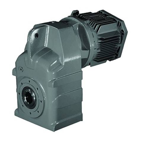
Benzlers Radicon G Series Maintenance and service guide

IMC-1.00GB01/11
Series G - Industrial Reducers
Installation & Maintenance

Product Safety Information
General - The following information is important in ensuring safety. It must be brought to the attention of personnel involved in the selection
of power transmission equipment, those responsible for the design of the machinery in which it is to be incorporated and those involved in its
installation, use and maintenance.
Our equipment will operate safely provided it is selected, installed, used and maintained properly. As with any power transmission equipment
proper precautions must be taken as indicated in the following paragraphs, to ensure safety.
Potential Hazards - these are not necessarily listed in any order of severity as the degree of danger varies in individual circumstances. It is
important therefore that the list is studied in its entirety:-
1) Fire/Explosion
(a) Oil mists and vapour are generated within gear units. It is therefore dangerous to use naked lights in the proximity of gearbox openings,
GXHWRWKHULVNRI¿UHRUH[SORVLRQ
E,QWKHHYHQWRI¿UHRUVHULRXVRYHUKHDWLQJRYHUR&FHUWDLQPDWHULDOVUXEEHUSODVWLFVHWFPD\GHFRPSRVHDQGSURGXFHIXPHV
&DUHVKRXOGEHWDNHQWRDYRLGH[SRVXUHWRWKHIXPHVDQGWKHUHPDLQVRIEXUQHGRURYHUKHDWHGSODVWLFUXEEHUPDWHULDOVVKRXOGEH
handled with rubber gloves.
2) Guards - Rotating shafts and couplings must be guarded to eliminate the possibility of physical contact or entanglement of clothing. It should
EHRIULJLGFRQVWUXFWLRQDQG¿UPO\VHFXUHG
1RLVH+LJKVSHHGJHDUER[HVDQGJHDUER[GULYHQPDFKLQHU\PD\SURGXFHQRLVHOHYHOVZKLFKDUHGDPDJLQJWRWKHKHDULQJZLWKSURORQJHG
exposure. Ear defenders should be provided for personnel in these circumstances. Reference should be made to the Department of
(PSOR\PHQW&RGHRI3UDFWLFHIRUUHGXFLQJH[SRVXUHRIHPSOR\HGSHUVRQVWRQRLVH
4) Lifting - Where provided (on larger units) only the lifting points or eyebolts must be used for lifting operations (see maintenance manual or
general arrangement drawing for lifting point positions). Failure to use the lifting points provided may result in personal injury and/or damage
to the product or surrounding equipment. Keep clear of raised equipment.
5) Lubricants and Lubrication
D3URORQJHGFRQWDFWZLWKOXEULFDQWVFDQEHGHWULPHQWDOWRWKHVNLQ7KHPDQXIDFWXUHU¶VLQVWUXFWLRQPXVWEHIROORZHGZKHQKDQGOLQJ
lubricants.
(b) The lubrication status of the equipment must be checked before commissioning. Read and carry out all instructions on the lubricant
SODWHDQGLQWKHLQVWDOODWLRQDQGPDLQWHQDQFHOLWHUDWXUH+HHGDOOZDUQLQJWDJV)DLOXUHWRGRVRFRXOGUHVXOWLQPHFKDQLFDOGDPDJHDQGLQ
extreme cases risk of injury to personnel.
6) Electrical Equipment - Observe hazard warnings on electrical equipment and isolate power before working on the gearbox or associated
equipment, in order to prevent the machinery being started.
7) Installation, Maintenance and Storage
(a) In the event that equipment is to be held in storage, for a period exceeding 6 months, prior to installation or commissioning, we must be
consulted regarding special preservation requirements. Unless otherwise agreed, equipment must be stored in a building protected from
extremes of temperature and humidity to prevent deterioration.
The rotating components (gears and shafts) must be turned a few revolutions once a month (to prevent bearings brinelling).
E([WHUQDOJHDUER[FRPSRQHQWVPD\EHVXSSOLHGZLWKSUHVHUYDWLYHPDWHULDOVDSSOLHGLQWKHIRUPRID³ZD[HG´WDSHRYHUZUDSRUZD[¿OP
preservative. Gloves should be worn when removing these materials. The former can be removed manually, the latter using white spirit as
a solvent.
3UHVHUYDWLYHVDSSOLHGWRWKHLQWHUQDOSDUWVRIWKHJHDUXQLWVGRQRWUHTXLUHUHPRYDOSULRUWRRSHUDWLRQ
F,QVWDOODWLRQPXVWEHSHUIRUPHGLQDFFRUGDQFHZLWKWKHPDQXIDFWXUHU¶VLQVWUXFWLRQVDQGEHXQGHUWDNHQE\VXLWDEO\TXDOL¿HGSHUVRQQHO
(d) Before working on a gearbox or associated equipment, ensure that the load has been removed from the system to eliminate the possibility
of any movement of the machinery and isolate power supply. Where necessary, provide mechanical means to ensure the machinery
cannot move or rotate. Ensure removal of such devices after work is complete.
(e) Ensure the proper maintenance of gearboxes in operation. Use only the correct tools and our approved spare parts for repair and
PDLQWHQDQFH&RQVXOWWKH0DLQWHQDQFH0DQXDOEHIRUHGLVPDQWOLQJRUSHUIRUPLQJPDLQWHQDQFHZRUN
+RW6XUIDFHVDQG/XEULFDQWV
D'XULQJRSHUDWLRQJHDUXQLWVPD\EHFRPHVXI¿FLHQWO\KRWWRFDXVHVNLQEXUQV&DUHPXVWEHWDNHQWRDYRLGDFFLGHQWDOFRQWDFW
E$IWHUH[WHQGHGUXQQLQJWKHOXEULFDQWLQJHDUXQLWVDQGOXEULFDWLRQV\VWHPVPD\UHDFKWHPSHUDWXUHVVXI¿FLHQWWRFDXVHEXUQV$OORZ
equipment to cool before servicing or performing adjustments.
9) Selection and Design
(a) Where gear units provide a backstop facility, ensure that back-up systems are provided if failure of the backstop device would endanger
personnel or result in damage.
(b) The driving and driven equipment must be correctly selected to ensure that the complete machinery installation will perform satisfactorily,
avoiding system critical speeds, system torsional vibration, etc.
(c) The equipment must not be operated in an environment or at speeds, powers, torques or with external loads beyond those for which it
was designed.
(d) As improvements in design are being made continually the contents of this catalogue are not to be regarded as binding in detail, and
drawings and capacities are subject to alterations without notice.
The above guidance is based on the current state of knowledge and our best assessment of the potential hazards in the operation of the gear units
.
$Q\IXUWKHULQIRUPDWLRQRUFODUL¿FDWLRQUHTXLUHGPD\EHREWDLQHGE\FRQWDFWLQJRXU$SSOLFDWLRQ(QJLQHHUV
IMPORTANT
PRODUCT SAFETY

SERIES G
Section Description Page No
1 Declaration of Conformity / Incorporation 1
1 General Information 2
2 Weather Protection 2
3 Reading the Nameplate 2
4 Marking 3
5 Installation
5.1 General Information 4
5.2 Prior to Installation 4
5.3 Fitting Components to Input or Output Shafts 4
5.4 Lifting 5
5.5 Installing Foot Mount Units 6
5.6 Installing Shaft Mount Units 6
5.7 Units for use in potentially explosive atmosphere 10
6 Lubrication
6.1 General Information 11
6.2 Temperature Limitations 11
6.3 Ventilator 11
6.4 Oil Level 11
6.5 Approved Lubricants 11
7 Motor Connections 12
8 Starting Up 12
9 Operation
9.1 Noise 12
9.2 General Safety 12
9.3 Units for use in potentially explosive atmosphere 12
10 Maintenance
10.1 Prior to any Maintenance Operations 13
10.2 Oil Plugs & Ventilator 13
10.3 Lubrication 13
10.4 Bearings 14
10.5 Grease Lubrication 14
10.6 Cleaning 14
11 Fault Diagnosis 15
Appendix
1 Cooling Coils 16
2 Lubrication Information 17-19
3 Approved Bearing Greases 20
4 Shaft Alignment 21-22
Safety Warning Symbols
SERIES G
Electrical Hazard
Could result in death or
serious injury
Danger (Touch Hazard)
Could result in death or
serious injury
Important notes on Explosion
Protection
Danger
Could result in serious, slight or
minor injuries
Damaging Situation
Could result in damage to gear unit
or driven machinery
Cleaning
Periodic cleaning necessary
RISK OF
ELECTRICAL
SHOCK
Pinch Points
Watch Your Hands
DANGER
CAUTION
STOP
CONTENTS PAGE

1
SERIES G
INFORMATION
Declaration of Conformity
Products:
Series G - Gear Units.
Radicon Transmission Uk Ltd hereby declares that products listed above have been designed in accordance
with the following Directives and Standards.
7KH0DFKLQHU\'LUHFWLYH(&
(1,627KH6DIHW\RI0DFKLQHU\
&RQIRUPVWRDOORWKHUKDUPRQLVHGVWDQGDUGVWHVWVDQGVSHFL¿FDWLRQV,QDVPXFKDVWKH\DSSO\WRRXU
products)
Declaration of Incorporation
According to Machinery Directive 2006/42/EC Annex IIB
This product must not be put into service until the machinery into which it is to be incorporated has been
declared in conformity with the provisions of the machinery directive 2006/42/EC.
The equipment shall only be loaded within the framework of our recommendations, and installed and
operated in accordance with our installation and maintenance instructions.
The company hereby draws attention to the dangers of improper use of this equipment and particularly
warns users against operating with inadequate guarding of rotating parts and the use of naked lights in close
proximity to the equipment.
Radicon Transmission Uk Ltd will, upon a reasoned request from national authorities, provide any relevant
information on its products
Signed by:
ENGINEERING MANAGER
Radicon Transmission UK Ltd
Radicon Transmission UK Limited
8QLW-/RZ¿HOGV%XVLQHVV3DUN
/RZ¿HOGV:D\(OODQG:HVW<RUNVKLUH+;'$
United Kingdom
7HO
)D[
www.radicon.com
Company No 7397993 England

SERIES G
2
1. General Information
The following instructions will help you achieve a satisfactory installation of your standard Series G gear unit,
ensuring the best possible conditions for a long and trouble free operation.
6HULHV*JHDUXQLWVDUHRIWHQVXSSOLHGPRGL¿HGWRVXLWFXVWRPHUUHTXLUHPHQWVRUDVSDUWRIDGULYHSDFNDJH
7KHVHLQVWUXFWLRQVVKDOOEHVXSSOHPHQWDU\WRDQ\LQIRUPDWLRQFRQWDLQHGRQWKHFHUWL¿HGDUUDQJHPHQWGUDZLQJ
DQGDQ\VHSDUDWHLQVWUXFWLRQVIRUHTXLSPHQW¿WWHGWRWKHJHDUXQLW$OOXQLWVDUHWHVWHGDQGFKHFNHGSULRUWR
despatch, a great deal of care is taken in packing and shipping arrangements to ensure that the unit arrives at
the customer in the approved condition.
2. Weather Protection of Unit
All Series G units are provided with protection against normal weather conditions. Where units are to operate in
extreme conditions, or where they are to stand for long periods without running, e.g. during plant construction,
consult our application engineers so that arrangements for adequate protection can be made.
3. Reading the Nameplate
3.1 8QLW,GHQWL¿FDWLRQ
Lubrication Grade
The lubrication grade is marked on the nameplate. See Appendix 2 for type and quantity of lubricant.
When requesting further information, or service
support quote the following information from the
nameplate:
8QLWW\SH0RGHO1R
2UGHU1XPEHU<HDURI0DQXIDFWXUH
SERIES G
LUBRICATION
Fill to correct Oil Level with oil of recommended grade.
'UDLQDQGÀXVKDWHQGRIRLOFKDQJHSHULRG6HHDSSURYHG
/XEULFDQWVOHDÀHWIRUIXUWKHUGHWDLOV
ORDER
No.
7<3(
RATIO
INPUT
POWER
OUTPUT
RPM
$66(0%/<
POSITION OIL
GRADE
Series G Torque Arm
Unit Size Case Construction
No. of Reductions Oil Level
Revision Number Cooling
Nominal Ratio Shaft Rotation
8QLW9HUVLRQ 8QLW+DQGLQJ
Output Shaft Type of Unit
Input Shaft Backstop
G143050.+- - - - R L 1 - - - -
INFORMATION

3
SERIES G
4. Marking
Units marked with this symbol are intended for use in industrial systems. Provided the units are correctly
VHOHFWHGDQGDUHLQVWDOOHGLQDFFRUGDQFHZLWKWKHVHLQVWUXFWLRQVgear units only) they comply with the EU
GLUHFWLYH(&$7(;D*URXS,,&DW]RQHV&DW]RQHV
0RWRUVFRXSOLQJVRUDQ\RWKHUHTXLSPHQW¿WWHGWRWKHJHDUXQLWPXVWDOVRFRPSO\ZLWKWKLVGLUHFWLYH,IWKHJHDU
unit is supplied as a geared motor package it is important to check the nameplates of the gear unit and the
motorRUDQ\RWKHUHTXLSPHQW¿WWHGFRUUHVSRQGVZLWKWKHFODVVL¿FDWLRQRIWKHSRWHQWLDOO\H[SORVLYHDWPRVSKHUH
in which the unit is to be installed.
Examples:
,,*=RQH RFFDVLRQDOKD]DUGRXVH[SORVLYHDWPRVSKHUH
,,*=RQH UDUHVKRUWWHUPKD]DUGRXVH[SORVLYHDWPRVSKHUH
,,'=RQH RFFDVLRQDOKD]DUGRXVH[SORVLYHDWPRVSKHUHGXULQJQRUPDORSHUDWLRQGXHWRSUHVHQFH
of combustible dust
,,'=RQH VKRUWWHUPKD]DUGRXVH[SORVLYHDWPRVSKHUHGXHWRSUHVHQFHRIFRPEXVWLEOHGXVWQR
hazard during normal operation
Temp class T3 Max. surface temperature 200°C
T4 Max. surface temperature 135°C
T5 Max. surface temperature 100°C
Protection type of gear unit
Ex-Atmosphere G = Gas
D = Dust
Category
Group
Understanding EU Directive 94/9/EC (ATEX 100a) Markings.
II 2 G EEx c,k, T4
INFORMATION

SERIES G
4
5. Installation
5.1 General
WARNING! The customer shall be responsible for the proper use of articles supplied by the company,
particularly the rotating shafts between their driving and driven members, and their guarding
for safety, and the company shall not be responsible for any injury or damage sustained as a
result of the improper use of the articles supplied.
Attention is hereby drawn to the danger of using naked lights in proximity to openings in
gearboxes and gear units supplied by the company, and the company shall not be liable for
any claim for injury or damage arising from any action in contravention of this warning.
:$51,1* $OO6HULHV*XQLWVDUHGHVSDWFKHGZLWKRXWRLORQLQVWDOOLQJWKHXQLW¿OOZLWKUHFRPPHQGHG
lubricant to correct level. In accordance with the details in section 6
5.2 Prior To Installation
5.2.1. Check gear unit has not ben damaged.
5.2.2. Check the gear unit / motor nameplate matches the requirements of the machine the unit is to be
installed into.
5.2.3. Thoroughly clean the gearbox mounting surfaces that are to be used and the shafts of paint & anti-
corrosion agents using a commercially available solvent. Ensure solvent does not make contact with
the oil seals.
5.3. Fitting Of Components To Either The Unit Input Or Output Shaft
7KHLQSXWRURXWSXWVKDIWH[WHQVLRQGLDPHWHUWROHUDQFHLVWR,62WROHUDQFHNIRUVKDIWGLDPHWHU
PPDQGPIRUVKDIWGLDPHWHU!PPDQGWKH¿WWHGFRPSRQHQWVVKRXOGEHWR,62WROHUDQFH0
IRUERUHGLDPHWHUPPDQG.IRUERUHGLDPHWHU!PP
5.3.1. Ensure shaft extensions, bores & keys etc are cleaned.
,WHPVVXFKDVJHDUVVSURFNHWVFRXSOLQJVHWFVKRXOGQRWEHKDPPHUHGRQWRWKHVHVKDIWVVLQFHWKLV
would damage the shaft support bearings.
7KHLWHPVKRXOGEHSXVKHGRQWRWKHVKDIWXVLQJDVFUHZMDFNGHYLFH¿WWHGLQWRWKHWKUHDGHGKROH
provided in the end of the shaft. See Table 1 below.
,WHPVEHLQJ¿WWHGPD\EHKHDWHGWR&WRDLGDVVHPEO\IXUWKHU
CAUTION
STOP
INFORMATION

5
SERIES G
Unit Size Type of Unit Input Shaft Output Shaft
14 & 16
Parallel 2 Stage M16 x 36 mm deep
M30 x 63 mm deepParallel 3 & 4 Stage M12 x 25 mm deep
Right Angle 3 Stage M12 x 32 mm deep
16 & 17
Parallel 2 Stage M20 x 43 mm deep
M42 x 81 mm deep
Parallel 3 & 4 Stage M16 x 36 mm deep
Right Angle 3 Stage M16 x 36 mm deep
Right Angle 4 Stage M12 x 32 mm deep
18 & 19
Parallel 2 Stage M24 x 52 mm deep
M42 x 81 mm deep
Parallel 3 & 4 Stage M20 x 43 mm deep
Right Angle 3 Stage M20 x 43 mm deep
Right Angle 4 Stage M16 x 36 mm deep
21 & 22
Parallel 2 Stage M30 x 63 mm deep
M42 x 81 mm deep
Parallel 3 & 4 Stage M20 x 43 mm deep
Right Angle 3 Stage M24 x 52 mm deep
Right Angle 4 Stage M20 x 43 mm deep
5.4 Lifting
2QO\WKHOLIWLQJSRLQWVLGHQWL¿HGEHORZPXVWEHXVHGIRUOLIWLQJRSHUDWLRQVGXULQJLQVWDOODWLRQ
Gearbox Only
The gearbox can be lifted using any of
the eight lifting points.
Gearbox on Bedplate
The lifting points on the gear unit and motor
must NOT be used to lift the whole drive
assembly. Use only the lifting points on the
EHGSODWHDVLGHQWL¿HGRQWKHDVVHPEO\GUDZLQJ
to lift the bedplate assembly.
Lifting point at all corners
Note: Failure to use these lifting points could result in personal injury / or damage to the product and
surrounding equipment.
Table 1
INSTALLATION

SERIES G
6
5.5 Foot Mounted Units
(QVXUHWKHEDVHIRXQGDWLRQPRXQWLQJVXUIDFHLVÀDWïYLEUDWLRQDEVRUELQJDQGWRUVLRQDOO\ULJLG
Note: Units on baseplates should if possible be mounted on the same bedplate as the prime mover.
7KHJHDUXQLWPXVWEHLQVWDOOHGLQWKHVSHFL¿HGPRXQWLQJSRVLWLRQ7KHPD[LPXPGHYLDWLRQIURPWKH
GHVLJQDWHGPRXQWLQJSRVLWLRQLVXQOHVVJHDUXQLWLVVXLWDEO\PRGL¿HGDQGDSSURYHGIRUQRQVWDQGDUG
mounting positions).
$OLJQXQLWVHH$SSHQGL[
Note: It is important to ensure when aligning unit on baseplate that all machined mounting points are
supported over their full area.
If steel packings are used, these should be placed either side of the foundation bolt as close as
possible.
'XULQJ¿QDOEROWLQJHQVXUHWKHXQLWRUEDVHSODWHLVQRWGLVWRUWHGDVWKLVZRXOGFDXVHVWUDLQVLQ
the gear case resulting in errors of alignment of shafts and gearing.
Check all mounting points are fully supported and adjust if necessary by using steel packings.
7RUTXHWLJKWHQEROWVWRWRUTXHVSHFL¿HGLQ7DEOHEHORZ
6HFXUHXQLWRUEDVHSODWHLI¿WWHGWRDULJLGIRXQGDWLRQXVLQJKHDY\GXW\EROWVWR,62JUDGHPLQLPXP
ï0D[LPXPSHUPLVVLEOHÀDWQHVVHUURUIRUPRXQWLQJVXUIDFHLVPP
5.6 Shaft Mounted Units
5.6.1. The following procedure is recommended for all shaft and foot / shaft mounted units.
&OHDQVKDIWH[WHQVLRQVGULYHQPDFKLQHVKDIWJHDUXQLWERUHDQGYHQWLODWRUZKHQ¿WWHG
5.6.1.2. Locate in position, ensuring it is as close as possible to the bearing on the driven machine.
5.6.1.3. Secure unit onto the shaft. For units using a shrink device refer to section 5.6.2.2.
5.6.1.4. Fit torque arm to the side of the unit adjacent to the driven machine where possible, as shown in
¿JXUHSDJH
1RWH8QOHVVVSHFL¿HGRWKHUZLVHWKHWRUTXHDUPZLOOEHVXSSOLHGORRVH
5.6.1.5. Anchor case to a secure point by means of the torque arm.
5.6.1.6. Fit guards in accordance with the factory acts.
5.6.1.7. Check motor wiring for correct direction of rotation, this is important when a backstop device is
¿WWHG
5.6.1.8. Fill gear unit with oil as detailed in section 6.
Set Screw Size Tightening Torque
M12 85 Nm
M16 200 Nm
M20 350 Nm
M24 610 Nm
M30 1220 Nm
M36 2150 Nm
M42 3460 Nm
Table 2
STOP
STOP
INSTALLATION

7
SERIES G
Torque arms are available for all shaft mounted units with parallel or right
angle shafts. They are supplied as optional extras and are secured to
gear cases as shown below.
7RUTXHDUPVPXVWEHVHFXUHGWRWKHFKDVVLVVWUXFWXUHLQDÀH[LEOH
mounting as indicated.
Shaft mounted units are designed to operate in the horizontal position.
Reference must be made to our Application Engineers, with details,
where units are required to operate in an inclined position.
SHAFT MOUNTED UNITS FOR HIGH INERTIA DRIVE
When used on Traverse drives with high inertia driven loads, eg crane
GULYHVVOHZLQJORQJWUDYHODQGFURVVWUDYHOERJLHGULYHVDQGVHOHFWHG
high inertia load roller table drives, it is recommended that shaft mounted
XQLWVVKRXOGEH¿WWHGZLWKVKRFNDEVRUELQJ7RUTXH$UPV
&RQVXOWRXU$SSOLFDWLRQ(QJLQHHUVZLWKVSHFL¿FDSSOLFDWLRQGHWDLOV
,WLVUHFRPPHQGHGWKDWWKHWRUTXHDUPLV¿WWHGRQWKHVLGHRIWKHXQLW
adjacent to the driven machine.
5.6.2. Shaft Mounted Units Using A Shrink Disc Device
7KHJHDUXQLWLV¿WWHGZLWKDµVKULQNGLVF¶GHYLFHORFDWHGRQWKHKROORZRXWSXWVKDIWWRSURYLGHDSRVLWLYH
RXWHUORFNLQJFRQQHFWLRQEHWZHHQJHDUXQLWDQGGULYHQVKDIW7KHµVKULQNGLVF¶LVDIULFWLRQGHYLFHZLWKRXW
keys, which exerts an external clamping force on the hollow output shaft, thus establishing a mechanical
VKULQN¿WEHWZHHQWKHJHDUXQLWKROORZVKDIWDQGGULYHQVKDIWµ6KULQNGLVF¶FDSDFLWLHVKDYHDPSOHPDUJLQV
in dealing with transmitted torques and external loading imposed on gear units.
5.6.2.1 Working Principle
7KHµVKULQNGLVF¶FRQVLVWVRIDORFNLQJFROODUDWDSHUHGLQQHUULQJDQGORFNLQJVFUHZV%\
tightening the locking screws, the locking collar and tapered inner ring are pulled together,
exerting radial forces on the inner ring, thus creating a positive friction connection between
KROORZVKDIWDQGGULYHQVKDIW6HH)LJXUH
As the tapered surfaces of locking collar and inner ring are lubricated with Molykote 321R or
similar and the taper angle is not self locking, locking collar will not seize on the inner ring and
can be released easily when removal is necessary.
Size of Unit ABB1CD EF G Disc Spring Ref X H
Min Max
14 490 135 55 195 95 40 60 M30 207 80 x 41 x 4 1.1 41
15 530
16 645 167 65 253 125 50 75 M36 262 100 x 51 x 6 1.1 52
17 700
18 845 222 80 328 150 70 105 M48 336 125 x 71 x 6 1.7 72
19 910
21 & 22 Contact our Application Engineers
Figure 1
7KHWRUTXHDUPPXVWEHÀH[LEO\
mounted to the chassis structure
Each pair of
disc springs to
be compressed
µ[¶PPRQ
assembly
Figure 2
INSTALLATION

SERIES G
8
When the shrink disc is clamped in position the high contact pressures between tapered surfaces and screw
heads and their seatings ensure hermetic sealing and eliminate the possibility of fretting corrosion.
Unit
Size
Customers Shaft Shrink Disc
Ød1 Ød2 Ød3 Ød4 l l1 l2 K Type B ØD ØG H M Torque
Ta (Nm)
14 95
h6 100
h6 94.5 115 413 55 50 M24
×50 +6'
120-81-95 22 120 197 53 M12 121
15 110
h6 115
h6 109.5 130 418 60 60 M24
×50 +6'
140-81-110 22 140 230 58 M14 193
16 125
h6 130
h6 124.5 147 530 70 70 M24
×50 +6'
160-81-125 28 160 290 68 M16 295
17 145
h6 150
h6 144.5 167 545 90 90 M30
×60 +6'
180-81-145 28 180 320 85 M16 295
18 160
h6 170
g6 159.5 185 685 90 90 M30
×60 +6'
200-81-160 30 200 340 85 M16 295
19 170
g6 180
g6 169.5 195 705 105 105 M30
×60 +6'
220-81-170 30 220 370 103 M20 570
21 210
g6 220
g6 209.5 225 820 130 105 M30
×60 +6'
260-81-210 30 260 430 119 M20 570
22 230
g6 240
g6 229.5 235 835 145 105 M30
×60 +6'
280-81-230 30 2 80 460 132 M20 570
Unit
Size
Hollow Shaft End Plate
ØD1 ØD2 ØD3 L L1 L2 L3 C C1 Ød5 Ød6 ØK1 M crs P Circlip
14 95 100 96 415 180 255 276 20 10.0
9.8 99.75
99.50 78 26 55 M12
D1300-
1000
15 110 115 111 420 180 260 276 20 10.0
9.8 114.75
114.50 90 26 65 M12
D1300-
1150
16 125 130 126 533 230 325 348 25 12.0
11.8 129.75
129.50 103 26 70 M16
D1300-
1300
17 145 150 147 548 230 340 348 25 12.0
11.8 149.75
149.50 120 33 85 M16
D1300-
1500
18 160 170 162 688 300 410 442 25 12.0
11.8 169.75
169.50 135 33 100 M16
D1300-
1700
19 170 180 172 708 300 430 442 25 12.0
11.8 184.75
184.50 150 33 110 M16
D1300-
1850
21 210 220 212 824 350 5000 510 28 14.0
13.8 219.75
219.50 170 33 130 M20
D1300-
2200
22 230 240 232 839 350 515 535 28 14.0
13.8 239.75
239.50 190 33 150 M20
D1300-
2400
Table 3
Customers Shaft
Hollow Shaft and
Shrink Disc End Plate
(if required)
Tapped
hole
3 rad
PD[
Circlip
hole
Screws M
WLJKWHQHGWR
torque Ta)
Recess for
end plate
Anti-Fretting bush Two tappings
µ3¶DW
min
INSTALLATION

9
SERIES G
5.6.2.2 Installation
µ6KULQNGLVFV¶DUHVXSSOLHGZLWKVKDIWPRXQWHGXQLWV7KHIROORZLQJSURFHGXUHVVKRXOGEH
IROORZHGZKHQ¿WWLQJRUUHPRYLQJXQLWVIURPWKHGULYHQVKDIW
5.6.2.2.1 Release locking screws gradually and in succession. Initially a quarter of a turn on
each screw will avoid tilting and jamming – do not remove locking bolts completely.
5HPRYHµVKULQNGLVF¶±IURPJHDUXQLWKROORZVKDIW
5.6.2.2.3 Clean and degrease locating diameters of gear unit hollow shaft, driven shaft and
µVKULQNGLVF¶ORFDWLQJGLDPHWHURQKROORZVKDIWH[WHQVLRQ
'UDZWKHJHDUXQLWRQWRWKHGULYHQVKDIW6HH)LJXUH
5.6.2.2.5 Grease tapered surfaces of outer ring and inner ring with Molykote 321R or similar.
)LWµVKULQNGLVF¶RQJHDUXQLWKROORZVKDIWWRSRVLWLRQVKRZQLQ)LJXUH
5.6.2.2.7 Tighten all locking screws gradually and in succession. Do not tighten in a
diametrically opposite sequence. Several passes are required until all screws are
WLJKWHQHGXQWLOWKHLQQHUDQGRXWHUULQJIDFHVDUHLQOLQHDQGWKHWRUTXH¿JXUHV7D
shown in the Table 3 are achieved.
5.6.2.2.8 Fit protective cover.
Note: When the hollow output shaft is to operate in a vertical position it is essential that the
shaft of the driven machine is provided with a shoulder. When the thrust load is not
taken by the shoulder on the driven shaft, a thrust plate, as shown in Figure 1, must
EH¿WWHG
,WLVUHFRPPHQGHGWKDWFXVWRPHUV¶VKDIWVDWWKHQRQFODPSHGHQGRIWKHVOHHYHVKRXOG
be coated with Molykote 321R or equivalent.
5.6.2.3 Removal
5.6.2.3.1 Removal procedure is similar to the reverse of installation.
1RWH'RQRWUHPRYHµVKULQNGLVF¶ORFNLQJVFUHZVFRPSOHWHO\
5.6.2.3.2 Remove any rust and dirt from gear unit hollow shaft.
:LWKGUDZJHDUXQLWIURPGULYHQVKDIW6HH)LJXUH
1RWH µ6KULQNGLVF¶VKRXOGEHUHPRYHGDQGFOHDQHGWKRURXJKO\DQG0RO\NRWH5RUVLPLODU
applied to the tapered surfaces of inner ring and locking collar before re-use.
1RWH 3URWHFWLYHFRYHUVDUHVXSSOLHGZLWKDOOµVKULQNGLVFV¶$VVHPEO\RUUHPRYDONLWVDQG
thrust plates are not provided..
Figure 6: Removing Gear Unit
Figure 5: Mounting Gear Unit
Screws
degreased Driven shaft use
Molykote 321R
RUVLPLODULQWKLV
area only)
Gear Unit
+ROORZ6KDIW
Inner ring
Locking collar
Anti-Fretting bush end plate
Jacking
screws
degreased
Unit hollow shaft
end plate
Jacking
screws
Nut
Shrink disc
Shaft
INSTALLATION

SERIES G
10
5.7. Units For Use In A Potentially Explosive Atmosphere
,IWKHXQLWKDVEHHQGDPDJHGLQWUDQVLWGRQRWXVH5HPRYHDOOWUDQVSRUW¿[WXUHVDQGSDFNLQJV
prior to start up)
&KHFNQDPHSODWHRIXQLWFRUUHVSRQGVZLWKWKHVLWHVSRWHQWLDOO\H[SORVLYHDWPRVSKHUHFODVVL¿FDWLRQ
&KHFNDPELHQWWHPSHUDWXUHIDOOVZLWKLQOXEULFDQWJUDGHUHFRPPHQGDWLRQV6HH$SSURYHG
Lubricants p27)
5.7.4. Make sure no potentially explosive atmosphere exists during installation.
0DNHVXUHWKDWJHDUXQLWLVVXI¿FLHQWO\YHQWLODWHGZLWKQRH[WHUQDOKHDWLQSXW±FRROLQJDLU
temperature should not exceed 40°C
(QVXUHPRXQWLQJSRVLWLRQFRUUHVSRQGVWRWKDWPDUNHGRQWKHQDPHSODWH1RWH$7(;DSSURYDOLV
RQO\YDOLGIRUPRXQWLQJSRVLWLRQVSHFL¿HGRQWKHQDPHSODWH
&KHFNPRWRUVFRXSOLQJVRUDQ\RWKHUHTXLSPHQW¿WWHGWRWKHJHDUXQLWKDV$7(;DSSURYDO
Check information listed on nameplates correspond to the environmental conditions of the site.
5.7.8. Ensure gearbox is not subjected to any loading greater than those marked on the nameplate.
5.7.9. For units operated with inverter drives, check motor suitability for use with the inverter.
Ensure that the inverter parameters do not exceed those of the motor.
5.7.10.For belt driven unitsFKHFNDOOEHOWV¿WWHGDUHRIVXI¿FLHQWHOHFWULFDOOHDNDJHUHVLVWDQFH9ȍ
(QVXUHJHDUXQLWDQGRWKHUHTXLSPHQWLVHOHFWULFDOO\JURXQGHG(DUWKHG
5.7.12.Check and adjust guards and covers so that there is no ignition source from sparks that may be
thrown by moving parts making contact with guards etc. Ensure coupling guards, covers etc are
dust tight or are designed in such a way that a build up of dust deposits cannot form when the unit
LVXVHGLQ=RQH=RQHFODVVL¿FDWLRQDUHDV
INSTALLATION

11
SERIES G
6. Lubrication
6.1. General
$OO6HULHV*XQLWVDUHGHVSDWFKHGZLWKRXWRLODZDUQLQJODEHOLVDWWDFKHGDQGWKHUHIRUH¿OOHGE\WKH
client. The grade and type of oil will be stamped on the nameplate in accordance with either of the types
of oil from Tables 2 or 3 in Appendix 2.
6.2. Temperature Limitations
&KHFNOXEULFDQWJUDGHVWDPSHGRQQDPHSODWHLVVXLWDEOHIRUWKHRSHUDWLQJDPELHQWWHPSHUDWXUHUDQJH
Consult Table L1.
6.3. Ventilator
6.3.1. Clean & secure the ventilator in the correct location for the required mounting position.
6.4. Oil Level
7KHDSSUR[LPDWHTXDQWLW\RIRLOUHTXLUHGLVJLYHQLQ7DEOH$SSHQGL[DQGWKHXQLWVKRXOGEH¿OOHGWRWKH
OHYHOPDUNHGRQWKHGLSVWLFNRUDQ\RWKHUOHYHOLQGLFDWRU¿WWHGVLJKWJODVVHWF
6.4.2. Where possible run the unit without load for a short time to circulate the lubricant thoroughly, then stop the
unit and re-check the oil level after allowing the unit to stand for 10 minutes and if necessary top up to the
FRUUHFWPDUNRQWKHGLSVWLFNRUDQ\RWKHUOHYHOLQGLFDWRU¿WWHGVLJKWJODVVHWF
:$51,1*'RQRWRYHU¿OODVH[FHVVPD\FDXVHRYHUKHDWLQJDQGOHDNDJH
&KHFNDQGUH¿WDOOSOXJVWLJKWHQWRFRUUHFWWRUTXH¿JXUH±VHHQRWHVLQPDLQWHQDQFHVHFWLRQ
Clean away any oil spillage from the surface of the gear unit and driven machinery.
6.5. Approved Lubricants
6.5.1. Oils
See Tables 2 and 3 Appendix 2 for lubricants approved for use in the gear unit.
6.5.2. Greases
See Appendix 3 for greases approved for use in the gear unit.
(ISO) Lubricant Ambient Temperature Range
-5°C to 20°C (type E)
-30°C to 20°C (type H) 0°C to 35°C 20°C to 50°C
CLP
&& EP Mineral Oil
W\SH( (9* (9* (9*
CLP
+&
3RO\DOSKDROH¿QEDVHG6\QWKHWLF
with EP additive
W\SH+
+9* +9* +9*
Table L1
CAUTION
CAUTION
LUBRICATION

SERIES G
12
7. Motor Connections
To mains:
&RQQHFWLRQRIWKHHOHFWULFPRWRUWRWKHPDLQVVXSSO\VKRXOGEHPDGHE\DTXDOL¿HGSHUVRQ7KHFXUUHQW
UDWLQJRIWKHPRWRUZLOOEHLGHQWL¿HGRQWKHPRWRUSODWHDQGFRUUHFWVL]LQJRIWKHFDEOHVWRHOHFWULFDO
regulations is essential.
Motor terminal connection:
7.2. Motor terminal connection should be made in accordance with appropriate documentation supplied by the
motor manufacturer.
8. Starting Up
8.1. Prior To Starting Up
(QVXUHYHQWLODWRULV¿WWHGVHHOXEULFDWLRQVHFWLRQ
8.1.2. Check oil level, top up if necessary.
(QVXUHDOOVDIHW\GHYLFHVDUHLQSODFHLHJXDUGV¿WWHG&KHFNDQGDGMXVWJXDUGVDQGFRYHUVVRWKDW
there is no ignition source from sparks that may be thrown by moving parts making contact with guards
etc. Ensure coupling guards, covers etc are dust tight or are designed in such a way that a build up of
GXVWGHSRVLWVFDQQRWIRUPZKHQWKHXQLWLVXVHGLQ=RQH=RQHFODVVL¿FDWLRQDUHDV
5HPRYHDQ\VDIHW\GHYLFHV¿WWHGWRSUHYHQWPDFKLQHURWDWLRQ
6WDUWLQJXSVKRXOGRQO\EHSHUIRUPHGRUVXSHUYLVHGE\VXLWDEO\TXDOL¿HGSHUVRQQHO
&DXWLRQ $Q\GHYLDWLRQIURPQRUPDORSHUDWLQJFRQGLWLRQVLQFUHDVHGWHPSHUDWXUHQRLVHYLEUDWLRQV
power consumption etc) suggests a malfunction, inform maintenance personnel immediately.
8QLWV¿WWHGZLWKEDFNVWRSHQVXUHPRWRULVFRUUHFWO\ZLUHGIRUIUHHGLUHFWLRQRIURWDWLRQ
9. Operation
9.1. Noise
7KHUDQJHRIXQFRROHGRUZDWHUFRROHG6HULHV*SURGXFWVDWLV¿HVDQRLVHVRXQGSUHVVXUHOHYHORI
G%$RUOHVVZKHQPHDVXUHGDWPHWUHIURPWKHXQLWVXUIDFH)DQFRROHGXQLWVPD\H[FHHGWKLVOHYHO
– Consult Application Engineering.
0HDVXUHPHQWVWDNHQLQDFFRUGDQFHZLWK%63W,62
9.2. General Safety
Potential hazards which can be encountered during installation, maintenance and operation of drives is
covered in greater detail in the product safety page at the front of this booklet.
Advice is also given on sensible precautions which need to be taken to avoid injury or damage.
PLEASE READ!
9.3. Initial Start Up For Gear Units Operating In A Potentially Explosive Atmosphere
During initial running in it is important to measure the gear unit maximum surface temperature when run
under maximum load after approximately 3 hours.operation. The maximum surface temperature must not
exceed 110°C for temperature class T3 & T4 and 80°C for T5. If this temperature is exceeded, shut down
immediately and contact Application Engineering.
RISK OF
ELECTRICAL
SHOCK
Pinch Points
Watch Your Hands
DANGER
CAUTION
START UP

13
SERIES G
10. Maintenance
10.1. Prior To Any Maintenance Operations
10.1.1.
De-energise the drive and secure against un-intentional switch on.
10.1.2.
Wait until the unit has cooled down – Danger of skin burns & pressure build up.
10.2. Oil Plugs / Ventilator
10.2.1.
Prior to removing plugs, ensure that the unit has cooled sufciently so that oil will not burn.
10.2.2.
Place a container under the oil drain plug to be removed. Note: it is recommended that the oil should be
slightly warm, (40-50°C) when drained. (Cooler oil will be more difcult to drain correctly).
10.2.3.
Top ups or rells should be done through the ventilator position.
10.2.4.
Remember to ret all plugs and torque tighten to Table M1 below.
10.2.5. Clean away any oil spillage.
10.3. Lubrication
10.3.1.Periodic inspection.
For Units tted with dipstick or other level indicating device, check the oil level every 3000 hours or 6
months whichever is sooner and if necessary top up with the recommended type of lubricant.
10.3.2.
Oil changes.
10.3.2.1. On all sizes regular oil changes are essential and the following factors should be used to
determine the frequency at which these are carried out.
a. Oil temperature – unit operating under load
b. Type of oil
c. Environment – humidity, dust, etc.
d. Operating conditions – shock, loading, etc.
10.3.2.2. At elevated temperatures the effective life of the oil is very much reduced. This is most
pronounced with oils containing fatty and EP additives. To prevent damage to the unit through
lubricant breakdown the oil should be renewed as detailed in Table M2.
Gear Unit Plug Size Tightening Torque
G 14 & 15 M22 65 Nm
G 16 & LARGER M33 130 Nm
Table M1
Unit Operating
Temperature ºC Mineral Oil CLP(CC) Type E Synthetic Oil CLP(HC) Type H
75 or LESS 17000 HOURS or 3 YEARS 26000 HOURS or 3 YEARS
80 12000 HOURS or 3 YEARS 26000 HOURS or 3 YEARS
85 8500 HOURS or 3 YEARS 21000 HOURS or 3 YEARS
90 6000 HOURS or 2 YEARS 15000 HOURS or 3 YEARS
95 4200 HOURS or 17 MONTHS 10500 HOURS or 3 YEARS
100 3000 HOURS or 12 MONTHS 7500 HOURS or 2.5 YEARS
105 2100 HOURS or 8 MONTHS 6200 HOURS or 2 YEARS
110 1500 HOURS or 6 MONTHS 5200 HOURS or 18 MONTHS
NB: INITIAL FILL OF OIL SHOULD BE CHANGED IN A NEW GEAR UNIT AFTER 1000 HOURS
OPERATION OR ONE YEAR OR HALF THE ABOVE LIFE WHICHEVER IS THE SOONEST.
Table M2
CAUTION
STOP
CAUTION
Pinch Points
Watch Your Hands
DANGER
MAINTENANCE

SERIES G
14
NOTE:
Figures quoted are for oil temperatures when the unit has attained normal running temperature
ZKHQRSHUDWLQJXQGHUORDG7KHVH¿JXUHVDUHEDVHGRQQRUPDOUXQQLQJEXWZKHUHFRQGLWLRQVDUH
particularly severe it may be necessary to change the oil more frequently. When changing lubricant,
LIVDPHOXEULFDQWLVQRWXVHGWKHQXQLWPXVWEHÀXVKHGRXWDQG¿OOHGZLWKRQHW\SHRIOXEULFDQW
Warning
Do not mix Synthetic and Mineral lubricants.
'RQRWRYHU¿OOWKHXQLWDVWKLVFDQFDXVHOHDNDJHDQGRYHUKHDWLQJ
10.3.3.For units installed in potentially explosive atmosphere it is essential to ensure that the oil is
FKDQJHGRQRUEHIRUHWKHUHQHZDOSHULRGVSHFL¿HGLQ7DEOH0
10.4. Bearings
10.4.1.Bearings should be replaced every 5 years for marked units. Alternatively they should be
UHSODFHGLQDFFRUGDQFHZLWKWKHDJUHHGVSHFL¿FDWLRQ
10.5. Grease Lubrication
10.5.1.On certain units the output bearings are grease lubricated, these should be regreased at 2000 to
3000 hour intervals unless otherwise instructed.
10.6. Cleaning
10.6.1.With the drive stationary periodically clean any dirt or dust from the gear unit and the electric motor
FRROLQJ¿QVDQGIDQJXDUGWRDLGFRROLQJ
10.6.2. Ensure build up of dirt or dust does not exceed 5mm.
CAUTION
MAINTENANCE

15
SERIES G
11. Fault Diagnosis
11.1. Gear Unit Problems:
,WLVQRUPDOIRUVPDOODPRXQWVRIRLOJUHDVHWROHDNRXWRIWKHRLOVHDOGXULQJWKHUXQQLQJLQSHULRGKRXUV
running time)
Symptom Possible Causes Remedy
Output shaft does not rotate,
even though the motor is
running or the input shaft is
rotating.
Drive between shafts interrupted in the gear
unit. Return the gear unit / geared motor for
repair.
Unusual, regular running
noise a) A meshing or grinding sound :damage to
bearings
b) A knocking sound : irregularity in gearing
D&KHFNRLO6HH0DLQWHQDQFH
b) Contact our Application Engineers or
\RXUORFDO6DOHV2I¿FH
Unusual, irregular running
noise Foreign matter present in the oil D&KHFNRLO6HH0DLQWHQDQFH
b) Stop the unit, contact our Application
(QJLQHHUVRU\RXUORFDO6DOHV2I¿FH
Oil leaking ï
IURPJHDUXQLWFRYHU
IURPPRWRUÀDQJH
IURPJHDUXQLWÀDQJH
IURPRXWSXWHQGRLOVHDO
a) Defective gasket on gear unit cover
b) Defective gasket
c) Gear unit not ventilated
a) Retighten screws on gear unit cover and
observe gear unit. If still oil leaks contact
our Application Engineers or your local
6DOHV2I¿FH
b) Contact our Application Engineers or
\RXUORFDO6DOHV2I¿FH
c) Vent the gear unit.
Oil leaking
from the ventilator
D*HDUXQLWRYHU¿OOHGZLWKRLO
b) Gear unit installed in an incorrect
mounting position
F)UHTXHQWFROGVWDUWVRLOIRDPLQJDQGRU
high oil level
D&RUUHFWWKHRLOOHYHO6HH/XEULFDWLRQ
b) Correct the mounting position and check
RLOOHYHO6HH/XEULFDWLRQ
F&KHFNWKHRLOOHYHO6HH/XEULFDWLRQ
:KHQFRQWDFWLQJRXUVDOHVRI¿FH
Please have the following information available:
1DPHSODWHGDWDFRPSOHWH
Type and extent of the problem encountered
The time and the circumstances the problem occurred
A possible cause
$Q\IXUWKHULQIRUPDWLRQRUFODUL¿FDWLRQUHTXLUHGPD\EHREWDLQHGE\FRQWDFWLQJ
2XUVDOHVRI¿FHSOHDVHVHHFRQWDFWGHWDLOVDWWKHEDFNRIWKLVERRNOHW
PROBLEM SOLVING

SERIES G
16
Cooling Coil.
&RROLQJFRLOVFDQEH¿WWHGWRDOOXQLWW\SHVDQGKDQGLQJV
Cooling coil connections for water inlet and outlet pipes are Ø12mm on all sizes.
3URWUXGLQJFRROLQJFRLOSLSHFDQEHFRQQHFWHGWRFXVWRPHU¶VSLSHZRUNYLDDVXLWDEOHVWUDLJKWFRXSOLQJ
:DWHUVXSSO\ &RROLQJFRLOVDUHVXLWDEOHIRUIUHVKEUDFNLVKRUVHDZDWHUZLWKÀRZLQHLWKHUGLUHFWLRQ
Connections are therefore interchangeable.
For best performance, the water supply should be at 10°C / 12°C temperature and at a
ÀRZUDWHRIOLWUHVPLQXWH
Size of Unit A B C
14 310 120 163
15 270 120 163
16 370 150 220
17 315 150 220
18 315 200 285
19 385 200 285
21 410 200 355
22 420 200 355
Gear
Case
APPENDIX 1

17
SERIES G
Approved Lubrication.
$OO6HULHV*XQLWVDUHGHVSDWFKHGZLWKRXWRLODZDUQLQJODEHOLVDWWDFKHGDQGWKHUHIRUH¿OOHGE\WKH
client. The grade and type of oil will be stamped on the nameplate in accordance with either of the types of
oil from Tables 2 or 3. The oil change period will be stated in Section 10.3 on Page 13.
7KHDSSUR[LPDWHTXDQWLW\RIRLOUHTXLUHGLVJLYHQLQ7DEOHEXWWKHXQLWVKRXOGDOZD\VEH¿OOHGWRWKHOHYHO
PDUNHGRQWKHGLSVWLFNRUDQ\RWKHUOHYHOLQGLFDWRU¿WWHGVLJKWJODVVHWF
WARNING'RQRWRYHU¿OODVH[FHVVPD\FDXVHRYHUKHDWLQJDQGOHDNDJH
Where possible run the unit without load for a short time to circulate the lubricant thoroughly, then stop the
unit and re-check the oil level after allowing the unit to stand for 10 minutes and if necessary top up to the
FRUUHFWPDUNRQWKHGLSVWLFNRUDQ\RWKHUOHYHOLQGLFDWRU¿WWHGVLJKWJODVVHWF
In addition where bearings are grease packed, the greases approved are given in Appendix 3.
Table 1 : Lubricant Quantity (Litres)
2LOTXDQWLWLHVDUHDSSUR[LPDWH¿OOWRWKHOHYHOPDUNHGRQWKHGLSVWLFNRUDQ\RWKHUOHYHOLQGLFDWRU¿WWHG
VLJKWJODVVHWF
'RQRWRYHU¿OODVH[FHVVPD\FDXVHRYHUKHDWLQJDQGOHDNDJH
Unit Type Unit Size
14 15 16 17 18 19 21 22
Parallel Shaft
2 Stage +RUL]RQWDO 22 20 47 42 92 95 180 161
Vertical 18 18 40 37 80 85 140 150
Parallel Shaft
3 Stage +RUL]RQWDO 21 19 46 41 91 94 185 175
Vertical 18 18 40 37 80 85 140 155
Parallel Shaft
4 Stage +RUL]RQWDO 21 19 46 41 91 94 185 175
Vertical 18 18 40 37 80 85 140 155
Right Angle
3 Stage +RUL]RQWDO 21 19 47 42 92 95 185 175
Vertical 20 20 43 39 87 92 140 170
Right Angle
4 Stage +RUL]RQWDO - - 48 43 94 96 190 175
Vertical - - 45 39 89 89 140 185
CAUTION
APPENDIX 2
Table of contents
Other Benzlers Industrial Equipment manuals
Popular Industrial Equipment manuals by other brands
MSW
MSW MSW-RM18S user manual
Afag
Afag CS 25 Series Montage & maintenance Instructions
Bend-Tech
Bend-Tech DRAGON A150 Original instructions
Vortec
Vortec 921 Series Operation & Safety Instructions
Aventics
Aventics 580 EtherNet/IP DLR Technical manual
Polar Instruments
Polar Instruments TONEOHM 850A Operator's manual
