Beretta HRT-177WS User manual

Manuale di installazione e uso pag. 2 IT
Installation and user instruction page 10 EN
Manuel d’installation et d’utilisation page 17 FR
Manual de instalación y uso pág. 25 ES
Manual de instalação e uso pag. 33 PT
Telepítői és felhasználói információk page 41 HU
Priručnik za ugradnju i uporabu str. 47 HR
Installatie- en gebruikershandleiding pag. 55 NL
Οδηγίες εγκατάστασης και χρήσης σελ. 63 GR
Instrukcja instalacji i użytkowania
strona 70
PL
HRT-177WS
CRONOTERMOSTATO SETTIMANALE
WEEKLY ROOM THERMOSTAT
CHRONOTHERMOSTAT HEBDOMADAIRE
CRONOTERMOSTATO SEMANAL
CRONO TERMÓSTATO SEMANAL
WEEKLY SZOBATERMOSZTÁT
TJEDNI KRONOTERMOSTAT
WEKELIJKSE KLOKTHERMOSTAAT
ΕΒΔΟΜΑΔΙΑΙΟΣ ΘΕΡΜΟΣΤΑΤΗΣ ΧΩΡΟΥ
PROGRAMATOR TYGODNIOWY

2
IT
QUESTE ISTRUZIONI DEVONO ESSERE CONSERVATE
DA PARTE DELL’UTENTE
Grazie per aver scelto questo cronotermostato settimanale.
Questo dispositivo di controllo dell’impianto riscaldamento
è di facile installazione e, se propriamente utilizzato, offre
una migliore qualità di comfort e un maggiore risparmio
energetico. Questo termostato è progettato per sostene-
re un carico elettrico massimo di 2A a 30VDC o 0,25A a
230VAC (specifiche del relè interno di commutazione del
collegamento “termostato ambiente” della caldaia). Se l’in-
stallazione è fatta da personale terzo, assicurarsi che que-
sto manuale sia consegnato all’utente finale.
Questo termostato può essere usato anche in modalità raf-
frescamento nel caso l’impianto sia predisposto.
ATTENZIONE: Si prega di leggere questo manuale prima
di procedere all’installazione e all’uso.
PERICOLO DI SCOSSE ELETTRICHE: Questo apparec-
chio deve essere installato da personale competente e se-
condo le norme vigenti in termini di installazioni elettriche.
Staccare sempre l’alimentazione elettrica prima di proce-
dere all’installazione.
ATTENZIONE PER L’INSTALLATORE: Il prodotto arriva
già impostato dalla fabbrica nella maggior parte dei sui pa-
rametri; il minimo richiesto alla prima installazione l’impo-
stazione dell’ora e del giorno della settimana.
IMPORTANTE: queste istruzioni devono essere lette as-
sieme a quanto riportato anche sul manuale della caldaia
riguardo al controllo del termostato ambiente. Si raccoman-
da che il dispositivo sia installato da personale qualificato.
MANOPOLA ENCODER
Tutte le tarature sono fatte da un’unica ma-
nopola – denominata ENCODER - che oltre a
ruotare in senso orario e antiorario, ha anche
la funzionalità di ENTER quando premuta.
Rotazione in senso orario e antiorario: au-
menta o diminuisce la temperatura “comfort” della stanza;
auto memorizzazione dopo 5 secondi.
Ruotare di uno scatto per verificare il valore impostato di
temperatura, dopo pochi lampeggi il display torna a visua-
lizzare la temperature ambiente.
Premere una volta l’encoder: si attiva o disattiva la fun-
zione “anticipo”.
Premere più a lungo l’encoder per entrare nel menù e
selezionare la modalità di uso o impostare ora / program-
mazione / parametri (vedi paragrafispecifici).
DISPLAY
ENCODER
APERTURA SENSORE

3
IT
DISPLAY LCD
SIMBOLO DESCRIZIONE / FUNZIONE
Modalità riscaldamento attiva (funziona-
mento invernale).
Icona non presente significa modalità raf-
frescamento attiva (funzionamento estivo).
MODALITÀ DI STATO
AUTO: il termostato utilizza le fasce pro-
grammate di attivazione o spegnimento del
riscaldamento (predefinite da fabbrica o
definite dall'utente).
OFF: il termostato è spento, in questo stato
nessuna richiesta di riscaldamento è attiva
tranne l’antigelo. (funzionamento estivo).
PARTY: richiesta di riscaldamento sempre
attiva a seconda della temperatura impo-
stata, le fasce orarie programmate sono
ignorate. Questa modalità rimane attiva
fino ad un suo spegnimento manuale.
ANTICIPO: la fascia oraria in corso viene
manualmente forzata all’accensione o allo
spegnimento anticipando la fascia succes-
siva. L’anticipo rimane attivo per la sola
fascia oraria in corso. Funzione attivabile
solo in caso di modalità AUTO accesa.
Il segmento indica il giorno della settimana.
Ora attuale oppure descrizione dei para-
metri all’interno del menù utente.
Fascia oraria giornaliera: 24 ore in seg-
menti di 60 minuti. Nell’esempio a lato la
fascia di riscaldamento è spenta fino alle
15:59 mentre è accesa dalle 16:00 alle
18:59.
Temperatura ambiente.
Batterie scariche
Richiesta di calore verso la caldaia attiva
(riscaldamento acceso)
Sono inoltre presenti, all’interno del menù utente, altre ico-
ne di seguito descritte.
SIMBOLO DESCRIZIONE / FUNZIONE
Selezione modalità riscaldamento (H = he-
ating) o raffrescamento (C = Cooling)
Selezione temperatura “Economy”

4
IT
Menù tecnico (solo per esperti)
Uscita dal menù
GUIDA VELOCE
Da leggere dopo aver impostato l’ora, il giorno e la modalità
di stato.
MODALITÀ DI FUNZIONAMENTO: Questo dispositivo for-
nisce sia la funzione di termostato ambiente sia la funzione
di orologio settimanale (cronotermostato).
In modalità AUTO il riscaldamento sarà acceso/spento in
base alla fascia oraria programmata e alla temperatura
di comfort selezionata (la richiesta di calore attiva è evi-
denziata dalla icona fiamma accesa). Nel caso ci si trovi
nella fascia oraria “spenta”, la temperatura di riferimento
è il valore “economy” (16°C valore di default) che è modifi-
cabile nel menù utente (la richiesta di calore è attiva se la
temperatura ambiente scende sotto la soglia temperatura
“economy”).
Nella modalità OFF (estate) la richiesta di calore viene
attivata solo se la temperatura della stanza scende sotto
il valore definito come “antigelo”, pre-configurato a 5°C e
modificabile all’interno del menù tecnico.
Nella modalità PARTY la richiesta di calore è sempre atti-
va a seconda della temperatura di comfort selezionata e
modificabile direttamente con l’encoder (premere per con-
fermare il valore).
Nella modalità COOLING (funzionamento estivo) il termo-
stato attiva o disattiva il sistema di raffrescamento. Questa
funzione è possibile solo se presente e collegato un siste-
ma centralizzato di raffrescamento.
ENCODER
L’encoder ha tre funzioni: selezione della temperatura desi-
derata, selezione della funzione “anticipo” e impostazione
dei vari parametri del termostato. Nel caso di modalità OFF
l’encoder è attivo solo per il movimento di selezione, men-
tre la rotazione non genera alcuna variazione.
1. Ruotare per selezionare la temperatura desiderata e
premere per confermare. La rotazione di un solo scat-
to dell’encoder permette di visualizzare la temperatura
“comfort” selezionata.
2. Premere una volta per attivare o disattivare la funzione
“anticipo”, funzione utilizzata per anticipare manualmen-
te la fascia di riscaldamento successiva alla attuale ad
una modalità acceso o spento.
3. Premere 3 secondi per accedere al menù utente. Ruota-
re per scorrere il menù tra modalità di stato del termosta-
to, impostazione della temperatura “economy”, imposta-
zione dell’ora del giorno, impostazione del giorno della
settimana, programmazione delle fasce di riscaldamen-
to giorno per giorno, ingresso nel menù tecnico (PL) e
uscita dal menù utente. Premere di nuovo per modificare
la voce selezionata.
Modalità di stato: ruotare per cambiare e selezionare una
delle tre modalità: AUTO, PARTY e OFF, premere per
confermare. La conferma di una delle tre modalità di stato
del cronotermostato fa uscire automaticamente dal menù
utente.
Temperatura “Economy” ECOt: Ruotare per selezionare
la temperatura di “economy” e premere per confermare.
Questa temperatura viene utilizzata quando, in modalità
AUTO, la fascia di programmazione del riscaldamento è
spenta. La temperatura della stanza non scenderà sotto

5
IT
questo valore.
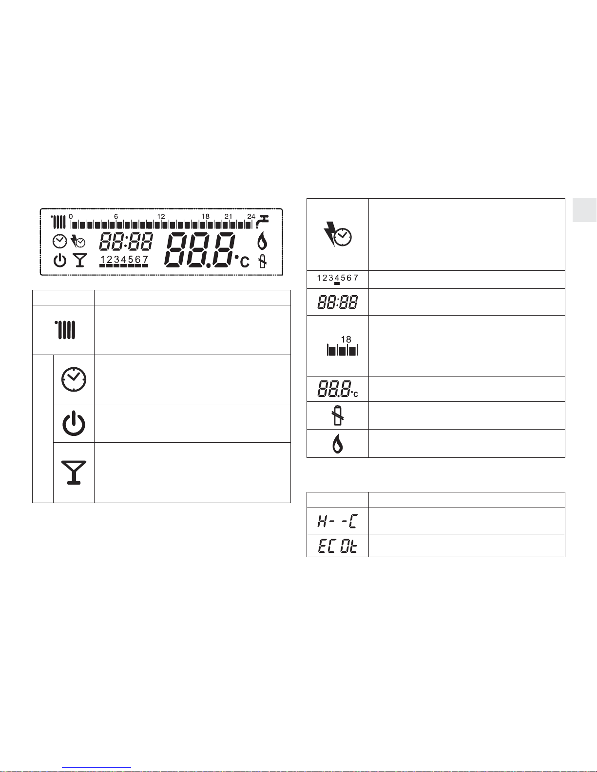
Selezione modalità riscaldamento o raffrescamento H- - C:
ruotare per selezionare tra Ht (riscaldamento) e CL (raffre-
scamento), premere per confermare. La modalità selezio-
nata può essere verificata a display dalla presenza o meno
dell’icona del radiatore (icona presente = modalità riscal-
damento, icona non presente = modalità raffrescamento).
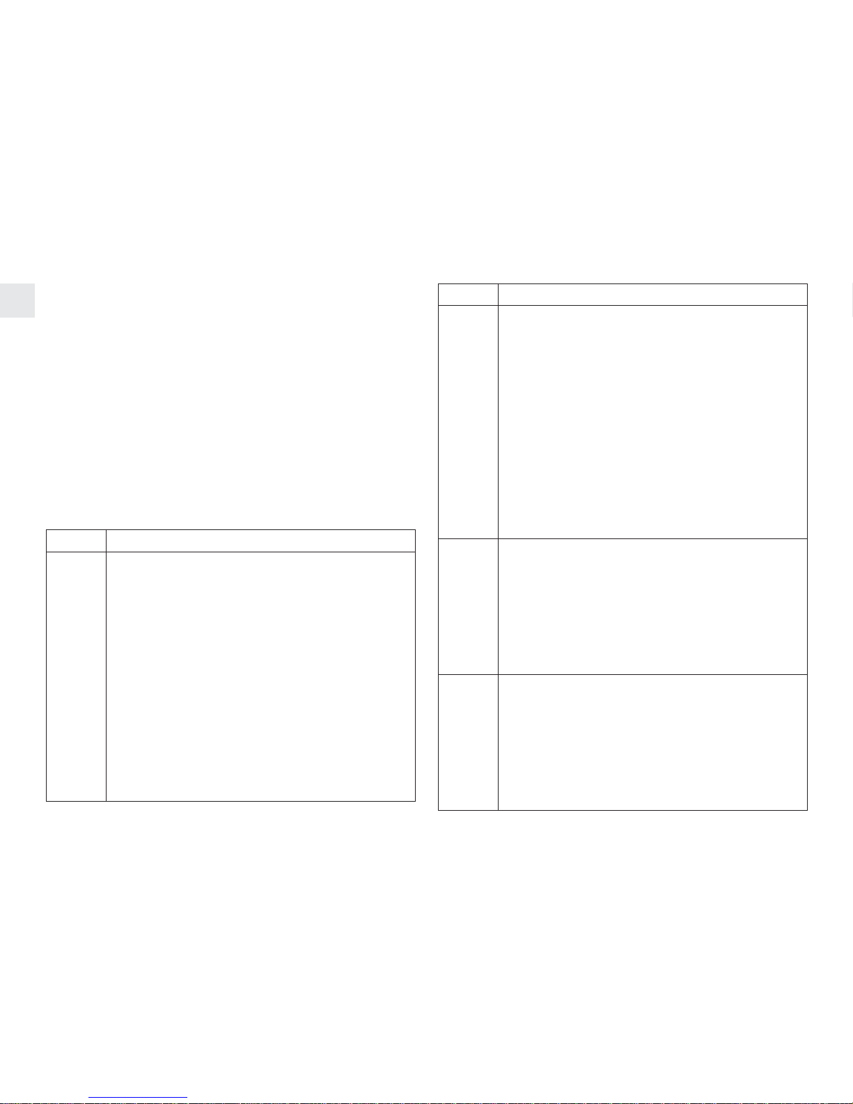
Ora del giorno: ruotare per modificare le ore, premere per
salvare. Passare ai minuti, ruotare per modificare i minuti,
premere per salvare.
Giorno della settimana: ruotare per cambiare il giorno, pre-
mere per salvare.
Programmazione fascia riscaldamento giorno 1-7: ruo-
tando in senso orario vengono selezionate accese le ore,
ruotando in senso antiorario vengono selezionate spente le
ore. La rotazione oraria e antioraria sposta sempre pro-
gressivamente in avanti il cursore. Premere per salvare.
Ruotare in senso orario o antiorario per passare al giorno
successivo o precedente, premere per entrare a modifica-
re la fascia del giorno selezionato. È anche possibile pro-
grammare con le medesime fasce orarie i giorni 1...5 e 6-7
mediante un’unica operazione.
PL: ruotare per selezionare il valore della password, pre-
mere per entrare all’interno del menù tecnico. Ruotare
per selezionare i parametri: 01 = calibrazione del sensore
di temperatura, 02 = selezione del valore di temperatura
antigelo, 03 = selezione del valore di isteresi OFF, 04 =
selezione del valore di isteresi ON, EHIt = uscire dal menù
tecnico. (per il menù tecnico leggere il paragrafo dedicato).
Exit: uscire dal menù utente.
INSTALLAZIONE E USO
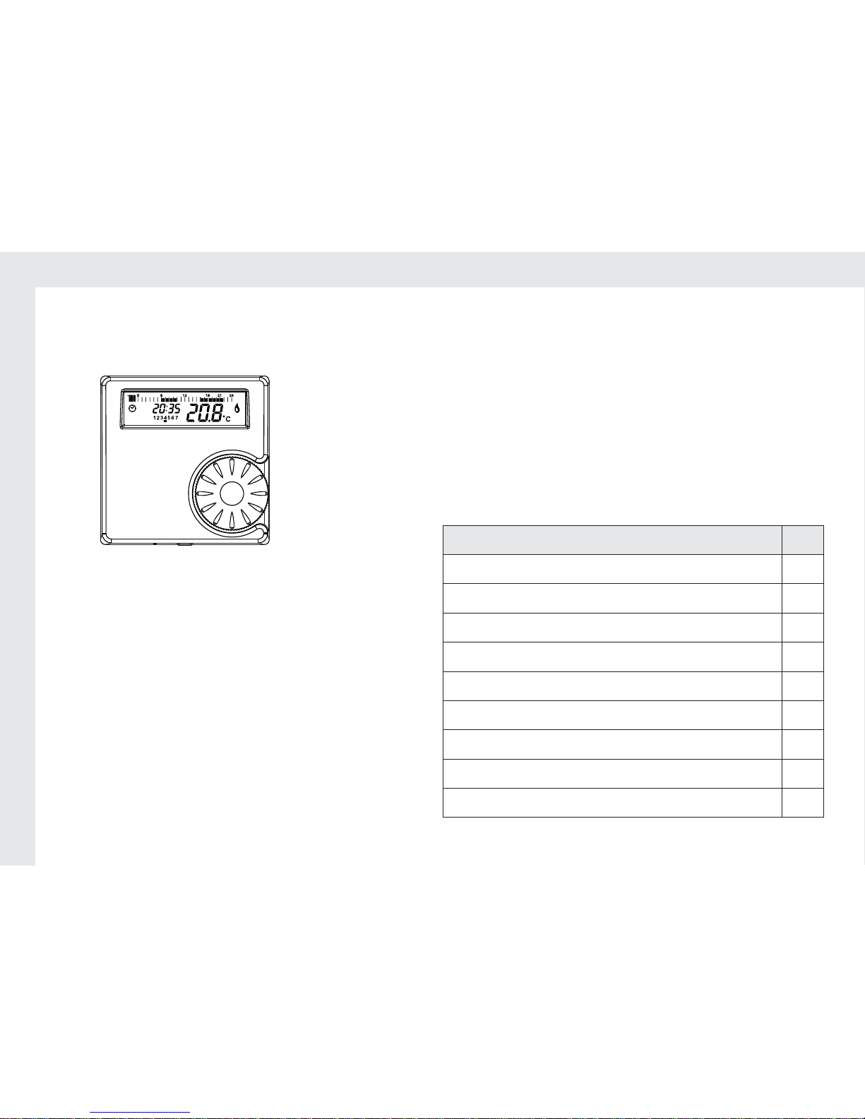
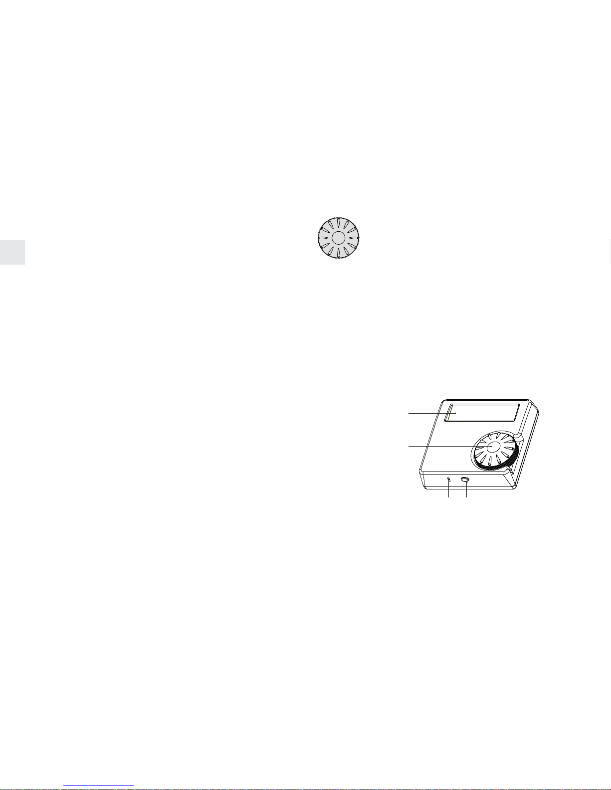
IL CRONOTERMOSTATO può es-
sere posizionato ovunque come un
qualsiasi termostato ambiente con-
venzionale. È necessario il collega-
mento mediante due fili tra la con-
nessione termostato ambiente della
caldaia e il cronotermostato. Non è
necessaria alcuna alimentazione
elettrica in quanto il cronotermostato
è alimentato mediante batterie.
CONTENUTO DELLA SCATOLA QTÀ
Cronotermostato 1
Tasselli e viti (Ø 5 mm) 2
Bi-adesivo 2
Manuale d’uso 1
Batterie 1,5V TIPO AAA 2
PREPARAZIONE DELLA CALDAIA
Isolare la caldaia dall’alimentazione elettri-
ca, aprire il cruscotto dove sono alloggiati i
collegamenti elettrici (per dettagli fare rife-
rimento al manuale di installazione e uso
della caldaia). Collegare mediante un cavo
con due fili (non forniti) i terminali del cro-
notermostato (vedi figura a lato) ai morsetti
del termostato ambiente sulla caldaia assicurandosi che le
caratteristiche elettriche tra quanto disponibile in caldaia e
il relè del cronotermostato siano compatibili (vedi paragra-
fo specifiche tecniche). La non compatibilità comporta un
mal funzionamento e pericolosità dell’installazione. Vedere
immagine successiva per una installazione tipica. La posi-
zione dei due fili rispetto ai morsetti è indifferente.

6
IT
JP1
JP2
JP3
JP4
JP5
JP6
CN6 CN5
CN12
1
CN13
P1 P3
P2
Remove the bridge
Black RF wires connections
NL
230 V
M3
F
brown
blue
brown RF
blue RF
IMPORTANTE: il ponticello (se presente) deve essere
rimosso dai morsetti termostato ambiente. Ancorare il ca-
blaggio del ricevitore assieme agli altri cavi della caldaia
per evitare strappi accidentali dei fili che potrebbero com-
promettere la sicurezza dell’installazione. Il cablaggio deve
essere conforme alle normative IEE.
INSTALLAZIONE DEL CRONOTERMOSTATO
Il termostato va installato in una
stanza riscaldata dal sistema di
riscaldamento gestito dal mede-
simo. Il fissaggio alla parete può
essere fatto mediante i tasselli e
le viti (aprire l’involucro) o utiliz-
zando i due biadesivi tutto fornito
a corredo. Vedere disegno a lato
per il riferimento della foratura, la
distanza tra due fori è di 60 mm,
foro Ø 5 mm. Per il funzionamento è necessario inserire le
due batterie fornite a corredo. Per inserire le batterie aprire
l’involucro del cronotermostato premendo il tasto posto sul
lato inferiore e fare leva sul lato superiore. Inserire le due
batterie secondo lo schema interno.
ATTENZIONE: Non toccare il circuito stampato del termo-
stato in quanto contiene componenti sensibili alle scariche
elettrostatiche.
FUNZIONI
Il cronotermostato settimanale senza fili fornisce le seguen-
ti funzionalità:
• Termostato ambiente: il sensore di temperatura interna
rileva la temperatura e, confrontandola con la tempera-
tura impostata (set point), attiva o disattiva la richiesta
di riscaldamento a seconda della fascia temprale e della
modalità di stato selezionata. Il sensore di temperatura si
trova sul lato inferiore del cronotermostato. Nel caso di
funzionamento in raffrescamento il termostato ambiente
funziona in modo opposto rispetto alla modalità riscalda-
mento: accende o spegne il sistema di raffrescamento
per mantenere la temperatura di comfort selezionata (in
raffrescamento è selezionabile un solo livello di tempe-
ratura).
• Ora: sul display è possibile impostare e leggere l’ora e il
giorno della settimana.
• Programmazione fasce orarie di riscaldamento: è pos-
sibile selezionare fasce orarie di riscaldamento acceso/
spento giorno per giorno a step di un’ora. La program-
mazione è possibile su di un arco temporale settimanale
(7 giorni).
• Modalità di stato: sono selezionabili AUTO, PARTY e
OFF. Selezionare la modalità AUTO se si desidera che il
riscaldamento segua le fasce orarie programmate; sele-
zionare la modalità PARTY per avere richiesta di riscalda-
mento costante (a seconda della temperatura di comfort
selezionata); selezionare la modalità OFF se non si vuole

7
IT
nessuna richiesta di riscaldamento attiva (funzionamento
estivo). Nota: la selezione estate/inverno è sempre me-
glio sia fatta direttamente sul cruscotto caldaia.
• Funzione “anticipo”: fascia pre-programmata successiva
alla attuale viene temporaneamente anticipata.
• Tre livelli di temperatura: comfort, “economy” e antigelo
• Funzione antigelo
• Batterie scariche
• Calibratura del sensore temperatura ambiente
• Selezione modalità riscaldamento o raffrescamento
ISTRUZIONI PER L’USO
Alla prima installazione del cronotermostato è necessario
impostare l’ora e il giorno della settimana (vedi paragrafo
encoder). Quindi va scelta una modalità di stato (si veda il
paragrafo encoder).
In AUTO la richiesta di riscaldamento segue le fasce orarie
impostate e la temperatura ambiente desiderata.
In PARTY il cronotermostato mantiene la temperatura di
comfort selezionata senza limiti temporali.
In OFF il cronotermostato è spento (tranne eventuale ri-
chiesta di calore per raggiunta temperatura antigelo).
Il cronotermostato arriva già con fasce orarie pre-impostate
(cfr. tabella sotto), ma queste possono essere modificate a
seconda delle esigenza dell’utente (cfr. paragrafo encoder)
Fasce di riscaldamento pre-impostate
GIORNO ON OFF ON OFF
Lunedì (giorno 1) 06:00 08:00 16:00 22:00
Martedì (giorno 2) 06:00 08:00 16:00 22:00
Mercoledì (giorno 3) 06:00 08:00 16:00 22:00
GIORNO ON OFF ON OFF
Giovedì (giorno 4) 06:00 08:00 16:00 22:00
Venerdì (giorno 5) 06:00 08:00 16:00 22:00
Sabato (giorno 6) 08:00 11:00 16:00 23:00
Domenica (giorno 7) 08:00 11:00 16:00 23:00
Altri valori impostati di fabbrica sono:
• Temperatura di comfort: 21 °C
• Temperatura “economy”: 16 °C
• Temperatura di protezione antigelo: 5 °C
• Isteresi OFF: 0,4 ° C (il riscaldamento viene spento a 0,4
°C al di sopra del target impostato)
• Isteresi ON: 0,2 ° C (il riscaldamento viene acceso a 0,2
°C sotto il target impostato)
BATTERIE SCARICHE
Le due batterie in dotazione sono garantite per durare
almeno 1 anno per un normale utilizzo dell’apparecchio.
Quando le batterie sono scariche la relativa icona apparirà
sul display. Meglio cambiare batterie in tempo per evitare ri-
chieste sbagliate di riscaldamento. Ogni volta che vengono
rimosse le batterie viene cancellata l’ora; le altre imposta-
zioni rimangono memorizzate. Nel caso di completo scari-
camento delle batterie, il relè (e di conseguenza la richiesta
o meno di calore) mantiene la stessa posizione avuta al
momento del completo spegnimento.

8
IT
PAR. DESCRIZIONE
02
TEMPERATURA ANTIGELO: Questo crono-
termostato è dotato di funzione antigelo che at-
tiva il riscaldamento, qualunque sia la modalità,
se la temperatura scende sotto un determinato
valore (ammesso che la caldaia sia impostata
in modalità inverno). Selezionando il parametro
02 è possibile modificare questa temperatura,
valore impostabile tra 3° e 10°C. Impostazio-
ne di fabbrica = 5 °C. La temperatura antigelo
diventa il minimo valore impostabile della tem-
peratura “economy”. ATTENZIONE! Questa
funzione non è da intendersi né come antige-
lo principale dell’impianto di riscaldamento né
come protezione della caldaia.
03
ISTERESI OFF: Il valore selezionato con que-
sto parametro indica l’isteresi di spegnimento
della richiesta di calore rispetto al set point. Il
valore pre-impostato di fabbrica è 0,4°C. Pa-
rametro selezionabile tra 0,0°C e 2,0°C. La ri-
chiesta di calore termina quando la temperatura
ambiente raggiunge il valore di set point addi-
zionato di questo valore selezionato.
04
ISTERESI ON: Il valore selezionato con questo
parametro indica l’isteresi di accensione della
richiesta di calore rispetto al set point. Il valore
pre-impostato di fabbrica è 0,2°C. Parametro
selezionabile tra 0,0°C e 2,0°C. La richiesta di
calore inizia quando la temperatura ambiente
scende sotto il valore di set point diminuito di
questo valore selezionato.
MENÙ TECNICO E FUNZIONI SPECIALI
(SOLO PER ESPERTI)
Il cronotermostato è dotato di una serie di parametri tecni-
ci accessibili solo mediante password attraverso specifico
menù tecnico. L’accesso e la modifica di questi parametri
sono raccomandati per solo personale esperto perché la
modifica cambia notevolmente il funzionamento del crono-
termostato e deve essere fatta solo se necessariamente
richiesto dal tipo di installazione. Il menù tecnico è accessi-
bile dal menù principale selezionando la posizione PL (cfr.
paragrafo encoder). La password richiesta per entrare è il
numero 53. All’interno del menù PL sono presenti 4 para-
metri che possono essere modificati come descritto di se-
guito.
PAR. DESCRIZIONE
01
TARATURA: È possibile calibrare il sensore
di temperatura del cronotermostato agendo su
questo parametro. Una volta entrati a display
comparirà il valore della temperatura che può
essere variato agendo sull’encoder. Premere
per memorizzare il nuovo valore. Da questo
momento il sensore di temperatura utilizza il
nuovo valore come riferimento. Per una cor-
retta taratura serve un termostato di parago-
ne. Questa operazione è consigliata solo se il
cronotermostato si trova in una posizione non
adeguata e che necessita pertanto di una va-
riazione del riferimento per rendere veritiero il
valore visualizzato rispetto alla reale tempera-
tura dell’ambiente.

9
IT
SPECIFICHE TECNICHE
Capacità di commutazione relè:
• Min 1mA,
• Max 2A a 30 Vc.c.
• Max 0,25 A a 230 VAC
Alimentazione: 2 batterie di tipo 1,5AAA
Impostazione delle temperature: da 3°C a 35°C in risolu-
zione di 0,2°C
Visualizzazione delle temperatura: da -9,9°C a 50°C in ri-
soluzione di 0,2 °C
Installare cronotermostato e ricevitore in un ambiente con
un normale quantità di polvere.
Il costruttore si riserva di variare le caratteristiche e i dati
riportati nel presente manuale in qualunque momento e
senza preavviso, nell’intento di migliorare il prodotto.

10
EN
THESE INSTRUCTIONS ARE TO BE RETAINED BY THE
USER
Thank you for choosing this thermostat. This central heat-
ing control device is easy to fit, and with correct use, will
deliver improved comfort levels in your home whilst saving
you money.
This thermostat is designed to be used only with heating
controls system with a maximum switching load of 2A at
30VDC or 0,25A at 230VAC.
If installing for someone else, please ensure that the in-
structions are handed to the householder.
This thermostat can also be used in summer in reverse
mode, in case of centralized cooling system.
WARNING: Please read this manual prior to installation or
use.
SHOCK HAZARD: This unit must be installed by a com-
petent person, in accordance with BS 7671 (the IEE Wiring
Regulations), or other relevant national regulations and
codes of good practice. Always isolate the AC Mains supply
before installing this unit.
FIRST INSTALLATION WARNING:The product arrives
with most of the parameters factory set with minimal ac-
tions required by the installer: wiring connections of the re-
ceiver to the boiler, setting the time and setting the day. All
the rest, like heating pattern, default temperatures, etc. are
already pre-configured at the factory.
IMPORTANT: these instructions should be read in con-
junction with the appliance installation instructions. It is
recommended that this device is installed by a qualified
electrician.
ENCODER KNOB
Encoder movements: clockwise and anticlock-
wise rotation, push to select.
Encoder clockwise and anticlockwise rota-
tion: increase or decrease the room comfort
temperature, auto enter of the selected value
after 5 seconds.
Encoder rotation one step: check the selected comfort
temperature. The value will blink for few times and later it
will be back to the room temperature value display.
Press and hold the encoder once to activate or de-activ-
ate the ADVANCE function.
Press and hold the encoder longer for enter in menu and
select the status mode or set the time/programming/para-
meters (see specific paragraph).
DISPLAY
ENCODER
OPENING SENSOR

11
EN
LCD DISPLAY
SYMBOL DESCRIPTION/FUNCTION
Heating mode is active (winter mode).
No icon means cooling mode is active
(summer mode).
STATUS MODE
AUTO: the thermostat uses the pro-
grammed heating pattern (default or user
defined) to switch the heating ON & OFF at
preselected times.
OFF: the thermostat is set to have the
heating constantly OFF (in this mode the
default or user defined heating pattern is
ignored) – summer mode.
PARTY: the thermostat is set to provide
heating constantly ON (in this mode the
default or user defined heating pattern is
ignored). This status stay ON up to end
user switching OFF
ADVANCE: the pre-programmed heating
pattern is advanced to the next ON (or
OFF) period (this function can only be used
when the clock is in the AUTO mode)
Used to show current day of week
Used to show current time of day or ex-
planation inside the main menu
24-hour clock in 60 minute segments. Side
example: The heating fascia is OFF up to
15:59 and it is ON from 16:00 to 18:59
Used to show current room temperature or
desired temperature to be selected.
Batteries low
Heat request to the boiler (central heating
ON)
Other icons inside the main menu:
SYMBOL DESCRIPTION/FUNCTION
Heating and Cooling mode selection
Economy temperature selection
Technical menu selection
(only for expertise)
Escape from main menu
QUICK START GUIDE
To be read and used after a proper installation has been
made and after the hours and the working mode has been
set.
WORKING MODE: This central heating control device

12
EN
provides you both the room thermostat function and the
weekly clock function.
When in AUTO mode, the central heating will be ON/OFF
according to the programmed times and according to the
set comfort temperature (the ON command is identified by
the flame icon). When the heating will be commanded ON
the set-point in the room will be the comfort one. In case of
off programmed times, the set temperature is the “economy
temperature”, selectable inside the main menu (16°C is the
default value).
When in OFF mode the heating requested will be switched
on when the room temperature drops under the frost pro-
tection value (default is 5°C); this value can be modified
inside the technical menu.
When in PARTY mode the heating request is permanently
on according the selected comfort temperature that can
be modified any time rotating the encoder and pressing to
confirm.
When in COOLING mode (summer mode) the room ther-
mostat activates or deactivates the cooling system. This
function must be used only if a cooling system is available
and only with an electric connection specifically made.
ENCODER
The encoder has three functions: selection of the set tem-
perature, set the ADVANCE function and setting the ther-
mostat. If the status mode of the thermostat is OFF, only the
pressing functionality is active; any rotation done does not
generate any modification.
1. Rotate to select the desired temperature and press to
enter.
2. Press once to activate or deactivate the ADVANCE
function. Use to “advance” the heating to an ON or OFF
period.
3. Press for 3 seconds to enter menu. Rotate to scroll
through the menu choosing between status mode, eco-
nomy temperature setting, time of day, day of the week,
programmed times day by day, technical menu (PL) and
exit. Press again to modify selected item.
Status mode: rotate to change the thermostat mode
between AUTO, PARTY, and OFF, press to save. The press
from status mode automatically escapes from menu.
Economy temperature ECOt: Rotate to select the desired
economy temperature and press to enter. This temperat-
ure is used when programming time is OFF in AUTO status
mode.
Heating and cooling mode selection H- -C: Rotate to select
the thermostat mode between Ht (heating) and CL (cool-
ing), press to save. The selected mode is identified on the
display with the presence of the radiator display (radiator
icon on means heating mode, radiator icon OFF means
cooling mode).
Time of the day: rotate to change the hours, press to save.
Move to minutes; rotate to change minutes, press to save.
Day of the week: rotate to change the day, press to save
Programmed times day 1-7: rotate clockwise to set hour
ON, rotate anticlockwise to select hour OFF. Clockwise and
anticlockwise rotation move ahead the time. Press to save.
Rotate clockwise to move to the following day. It is possible
to program together days 1…5 and days 6-7 with the same
pattern in a single operation.
PL: rotate to select the password value, press to enter in-
side the technical menu. Rotate to select the parameters:
01 = calibration of the temperature sensor, 02 = frost pro-
tection temperature selection, 03 = hysteresis OFF value

13
EN
selection, 04 = hysteresis ON value selection, EHIt = es-
cape from technical menu. (for technical menu see dedic-
ated paragraph).
Exit: escape from main menu.
INSTALLATION AND OPERATING INSTRUCTIONS
THE THERMOSTAT is a wall-moun-
ted timer-thermostat. It can be loc-
ated wherever a conventional room
thermostat would normally be sited.
The thermostat need to be wired
with the boiler only for the room ther-
mostat connection, no high voltage
supply is required as it is battery
powered. It must be connected to
the boiler and it can replace a conventional mechanical or
electronic time clock.
PACKING LIST QTY
Time-thermostat 1
Screws and wall plugs (drill 5 mm) 2
Double side adhesive 2
Instructions 1
Batteries 1,5 AAA 2
BOILER PREPARATION
Isolate the appliance from the electrical
supply and remove the appliance casing
and PCB cover (refer to boiler installation
instructions for specific details).Identify on
the boiler control board the room thermo-
stat connection. Connect two wires (not
supplied) from the thermostat terminals – side picture for
thermostat terminals - to the boiler PCB terminals (room
thermostat terminal) - figure below for a sample boiler con-
nections. The wiring connection is interchangeable.
JP1
JP2
JP3
JP4
JP5
JP6
CN6 CN5
CN12
1
CN13
P1 P3
P2
Remove the bridge
Black RF wires connections
NL
230 V
M3
F
brown
blue
brown RF
blue RF
IMPORTANT: the link-wire (if fitted) must be removed from
room thermostat terminals. Secure the wiring harness to
the internal boiler cable anchors. Wiring must conform to
IEE regulations.
IMPORTANT: This thermostat is designed to be used only
with heating controls system with a maximum switching
load of 2A at 30VDC or 0,25A at 230VAC.
INSTALLATION OF THERMOSTAT
Position the thermostat on a
wall surface away from obstruc-
tions and direct heat sources
or draughts, in a room that is
warmed by the heating system.
The fixing of the thermostat can
be done either with the screws
and wall plug or with the double
side adhesive depending on the
wall surface quality (both sup-
plied). See the side diagram as reference to drill the wall.

14
EN
Distance between 2 holes is 60 mm, drill hole dia. 5 mm.
In the case of using wall plug, the thermostat box must
be open to fix the screws to the wall plug from inside the
box. The opening of the thermostat must be done pressing
gently the lower button and leverage on the upper side. Fit
the supplied two batteries inside the thermostat with the
direction as indicated internally.
WARNING: Do not touch the printed circuit board of the ther-
mostat as it contains electrostatically sensitive components.
FUNCTIONS
The weekly thermostat has the following functions:
• Room thermostat: the internal temperature sensor de-
tects the temperature and, comparing with the set point,
switches ON or OFF the heating request (according the
programmed timings). The temperature sensor is located
on the lower side of the item. In case of cooling mode
selection, the room thermostat works in a opposite way
compared to the heating mode and it switches ON or OFF
the cooling system if connected (when in cooling mode,
only the comfort temperature is selectable).
• Time: on the display it is possible to set and read the time
(weekly hours display mode)
• Programming timing: it is possible to select the desired
ON or OFF heating times. The programming is possible
during one week 24-hours and the minimum time seg-
ment is one hour.
• Status mode: AUTO, PARTY, OFF: Select AUTO mode if
timed ON/OFF period are required. Select PARTY mode
for constant ON (24-hours). Select OFF mode for heating
OFF (summer mode). Note: summer/winter selection is
better to be selected on the main boiler dashboard.
• ADVANCE functions: the pre-programmed heating pat-
tern is advanced to the next ON (or OFF) period
• 3 level temperatures: comfort, economy and frost protection
• Frost protection functionality
• Battery low
• Room temperature calibration
• Heating and cooling mode selection
OPERATING INSTRUCTIONS
At the first installation the thermostat, the time and the day
of the week needs to be set (see encoder paragraph). After
this, a desired thermostat status must be selected (see
the encoder paragraph). When in AUTO mode the heating
request follows the programmed heating pattern and the
desired room temperature selected.
When in PARTY mode the heating request is ON all the
time according the desired room temperature selected.
When in OFF mode, the heating request is OFF all the time
(frost protection is ON).
The thermostat is pre-programmed with a default heating
pattern (see table below); however this can be modified to
suit individual needs (see encoder paragraph)
PRE-PROGRAMMED HEATING PATTERN
Day ON OFF ON OFF
Monday (day 1) 06:00 08:00 16:00 22:00
Tuesday (day 2) 06:00 08:00 16:00 22:00
Wednesday (day 3) 06:00 08:00 16:00 22:00
Thursday (day 4) 06:00 08:00 16:00 22:00
Friday (day 5) 06:00 08:00 16:00 22:00
Saturday (day 6) 08:00 11:00 16:00 23:00
Sunday (day 7) 08:00 11:00 16:00 23:00

15
EN
Other factory set values are:
• Comfort temperature: 21°C
• Economy temperature: 16°C
• Frost protection temperature: 5°C
• Hysteresis OFF: 0,4°C (boiler switch OFF at 0,4°C above
the target)
• Hysteresis ON: 0,2°C (boiler switch ON at 0,2°C below
the target)
LOW BATTERIES
The two supplied batteries will last for approximately 1 year
under a normal usage. When the batteries are low, the re-
lative icon will appear on the display. It is better to change
the batteries on time in order avoid any lack of heating sup-
ply during the day.
Follow the correct positioning of the batteries according to
the internal thermostat battery box indications.
Every time the batteries are removed the thermostat loses
only the time. The programmed times and the set temper-
atures are maintained memorized.
In the case of completely empty batteries, at the moment of
the final switching OFF, the relay position (and therefore the
heat request) remains as it was in that moment
TECHNICAL MENU AND SPECIAL FUNCTIONS
(ONLY FOR EXPERTISE)
The weekly thermostat incorporates a technical parameter-
ized menu accessible only with a password and the use of
this is recommended for expert personnel only.
The parameter settings change the working mode of the
thermostat, therefore the modifications are allowed only if
required by the particular installation.
The technical menu is accessible by the main menu under
the PL icon (see encoder paragraph for the access proced-
ure). The password to be selected is the number 53.
Inside the PL menu are present 4 parameters that can be
adjusted as described below:
PAR. DESCRIPTION
01
CALIBRATION: It is possible to calibrate the
temperature sensor by entering the 01 para-
meter. On the display will appear only the tem-
perature. Use the encoder to increase or de-
crease the temperature. Press the encoder to
enter the new value. From now the thermostat
uses the new value as current room temperat-
ure. Please note that for the calibration it is ne-
cessary to have a second thermometer that will
be used as master. This operation is suggested
only if the thermostat is fixed in a non-appropri-
ate position, therefore it is necessary to modify
the value on the display to be according the real
room temperature.

16
EN
PAR. DESCRIPTION
04
HYSTERESIS ON: The value selected with this
parameter indicates when the heat request is
activated. The factory setting is 0,2°C, values
range between 0,0°C and 2,0°C. Heat requests
switch ON when the room temperature drop
below the room target temperature minus the
hysteresis ON value.
TECHNICAL SPECIFICATIONS
Relay switching capacity:
• Min 1mA,
• Max 2A a 30 Vc.c.
• Max 0,25 A a 230 VAC
Power rating: 2 x 1,5AAA - Alkaline batteries
Temperature setting: 3°C to 35°C in 0.2°C increments.
Display temperature: -9,9°C to 50°C in 0.2°C increments.
Install the thermostat in an environment with normal pol-
lution level.
The manufacturer reserves the right to change specifica-
tion without prior notice - Consumers statutory rights are
not affected.
PAR. DESCRIPTION
02
FROST PROTECTION TEMPERATURE: The
weekly room thermostat has an internal an-
ti-frost function that switches on the boiler (only
when the boiler is properly set to allow the room
thermostat to activate/deactivate the boiler, i.e.
boiler in winter mode) if the room temperature
drops below the selected temperature. This
function is active all the time whatever the pro-
gramming time or the set temperature. By en-
tering the 02 parameter it is possible to adjust
the frost protection temperature: the factory
setting is 5°C, the 02 parameter can be adjus-
ted between 3°C and 10°C. the frost protection
selected temperature becomes the minimum
settable value for the economy temperature (in-
side the main menu). WARNING! This anti-frost
protection is not intended to be the main con-
trol to protect the entire heating system and the
boiler during a freezing period.
03
HYSTERESIS OFF: The value selected with
this parameter indicates when the heat request
is stopped. The factory setting is 0,4°C, val-
ues range between 0,0°C and 2,0°C. Heat re-
quests switch OFF when the room temperature
reaches the room target temperature plus the
hysteresis OFF value.
EN

17
FR
L’UTILISATEUR DOIT CONSERVER CES INSTRUC-
TIONS
Merci d’avoir choisi ce chrono thermostat hebdomadaire.
Ce dispositif de contrôle de l’installation de chauffage est
facile à monter et, utilisé correctement, il offre un confort
de meilleure qualité et garantit des économies d‘énergies
plus importantes. Ce thermostat est conçu pour supporter
une charge électrique maximum de 2° à 30 V cc ou 0,25 A
à 230 V ca (caractéristiques du relais intérieur de commu-
tation de la connexion « thermostat ambiance » de la chau-
dière). Si le montage est accompli par un tiers, veillez à que
ce manuel soit remis à l’utilisateur final.
Ce thermostat peut aussi être utilisé en mode rafraîchisse-
ment si l’installation est aménagée dans ce but.
ATTENTION: Veuillez lire ce manuel avant de procéder au
montage et à l’utilisation.
DANGER D’ELECTROCUTIONS: Cet appareil doit être
monté par du personnel compétent, conformément aux
normes en vigueur sur les installations électriques. Coupez
toujours l’alimentation électrique avant de procéder au
montage.
ATTENTION POUR LE MONTEUR: Cet appareil arrive
avec la plupart des paramètres déjà configurés en usine
; le minimum requis lors de la première installation est la
configuration de l’heure et du jour de la semaine.
IMPORTANT : ces instructions doivent être lues avec les
indications du manuel de la chaudière sur le contrôle du
thermostat d’ambiance. Nous recommandons de faire ins-
taller le dispositif par du personnel qualifié.
MANETTE ENCODEUR
Tous les étalonnages se font avec une seule
manette - appelée ENCODEUR, qui tourne en
sens horaire et en sens antihoraire et qui, en-
foncée, fait office d’ENTER.
Rotation en sens horaire et antihoraire:
augmente ou diminue la température “confort” de la pièce ;
auto-mémorisation après 5 secondes.
Tourner d’un tour pour vérifier la valeur configurée pour
la température, après quelques clignotements l’afficheur
affiche à nouveau la température ambiante.
Appuyer une fois sur l’encodeur: active ou désactive la
fonction “avance”.
Appuyer plus longtemps sur l’encodeur pour entrer
dans le menu et sélectionner le mode d’utilisation ou confi-
gurer l’heure/la programmation/les paramètres (cf. para-
graphes spécifiques).
AFFICHEUR
ENCODER
OUVERTURE CAPTEUR

18
FR
AFFICHEUR LCD
SYMBOLE DESCRIPTION/FONCTION
Mode chauffage actif (fonctionnement d’hi-
ver).
Icône non présente, cela signifie mode ra-
fraîchissement actif (fonctionnement d’été).
MODE D’ETAT
AUTO: le thermostat utilise les plages
d'activation ou d’extinction du chauffage
programmées (préétablies en usine ou
établies par l'utilisateur).
OFF: le thermostat est éteint, dans cet état
aucune demande de chauffage n’est active
hormis l’antigel. (fonctionnement d’été).
PARTY: demande de chauffage toujours
active selon la température configurée,
les plages horaires programmées sont
ignorées. Ce mode reste actif tant qu’il
n’est pas éteint manuellement.
AVANCE: la plage horaire en cours est for-
cée à l’allumage ou à l’extinction manuel-
lement en anticipant la plage successive.
L’avance ne reste active que pour la plage
horaire en cours. Fonction activable uni-
quement avec le mode AUTO allumé.
Le segment indique le jour de la semaine.
Heure réelle ou description des paramè-
tres à l’intérieur du menu utilisateur.
Plage horaire quotidienne: 24 heures en
segments de 60 minutes. Dans l’exemple
ci-contre la plage de chauffage est éteinte
jusqu’à 15h59 et allumée de 16h00 à
18h59.
Température ambiante.
Batteries déchargées.
Demande de chaleur vers la chaudière ac-
tive (chauffage éclairé).
D’autres icônes, décrites ci-après, sont présentes dans le
menu utilisateur.
SYMBOLE DESCRIPTION/FONCTION
Sélection du mode chauffage (H=heating)
ou rafraîchissement (C=Cooling)
Sélection température « Economy »

19
FR
Menu technique (uniquement pour expéri-
mentés)
Sortie du menu
GUIDE RAPIDE
A lire après avoir configuré l’heure, le jour et le mode d’état.
MODE DE FONCTIONNEMENT: Ce dispositif remplit à
la fois la fonction de thermostat d’ambiance et la fonction
d’horloge hebdomadaire (chronothermostat).
En mode AUTO le chauffage sera allumé/éteint selon la
plage horaire programmée et la température de confort
sélectionnée (la demande de chaleur active est indiquée
par l’icône de la flamme allumée). Si on se trouve dans
la plage horaire éteint la température de référence est la
valeur « economy » (16°C valeur par défaut), modifiable
dans le menu utilisateur (la demande de chaleur est active
si la température ambiante descend au-dessous du seuil
de température « economy »).
En mode OFF (été) la demande de chaleur n’est activée
que si la température de la pièce descende au-dessous de
la valeur établie comme « antigel » préconfigurée à 5°C et
modifiable dans le menu technique.
En mode PARTY la demande de chaleur est toujours ac-
tive selon la température de confort sélectionnée et direc-
tement modifiable avec l’encodeur (appuyer pour confirmer
la valeur).
En mode COOLING (fonctionnement d’été) le thermostat
active ou désactive le système de rafraîchissement. Cette
fonction n’est possible que si un système centralisé de ra-
fraîchissement est présent et connecté.
ENCODER
L’encodeur a trois fonctions: sélection de la température
désirée, sélection de la fonction “avance” et configuration
des différents paramètres du thermostat. En mode OFF
l’encodeur n’est actif que pour le mouvement de sélection,
tandis que la rotation ne génère aucune variation.
1. Faire tourner pour sélectionner la température voulue
et appuyer pour confirmer. La rotation d’un seul tour de
l’encodeur permet d’afficher la température « confort »
sélectionnée.
2. Appuyer une fois pour activer ou désactiver la fonction «
avance », utilisée pour anticiper manuellement la plage
de chauffage successive ne mode allumé ou éteint.
3. Appuyer 3 secondes pour accéder au menu utilisateur.
Faire tourner pour faire défiler le menu entre les modes
état du thermostat, configuration de la température «
economy », configuration de l’heure du jour, configura-
tion du jour de la semaine, programmation des plages
de chauffage jour après jour, entrée dans le menu tech-
nique (PL) et sortir du menu utilisateur. Appuyer à nou-
veau pour modifier l’élément sélectionné.
Mode d’état: faire tourner pour changer et sélectionner
l’un des trois modes: AUTO, PARTY et OFF, appuyer pour
confirmer. La confirmation de l’un des trois modes d’état
du chronothermostat fait automatiquement sortir du menu
utilisateur.
Température Economy ECOt: Faire tourner pour sélec-
tionner la température « economy » et appuyer pour confir-
mer. Cette température est utilisée en mode AUTO lorsque
la plage de programmation du chauffage est éteinte. La
température de la pièce ne descend pas au-dessous de
cette valeur.
Sélection du mode chauffage ou rafraîchissement H- - C:

20
FR
faire tourner pour sélectionner entre Ht (chauffage) et CL
(rafraîchissement), appuyer pour confirmer. L’afficheur per-
met de vérifier le mode sélectionné : présence ou absence
de l’icône du radiateur (icône présente = mode chauffage,
icône absente = mode rafraîchissement).
Heure du jour: faire tourner pour modifier les heures, ap-
puyer pour sauvegarder. Passer aux minutes, faire tourner
pour modifier les minutes, appuyer pour sauvegarder.
Jour de la semaine: faire tourner pour modifier le jour, ap-
puyer pour sauvegarder.
Programmation plage de chauffage jour 1-7: en faisant
tourner en sens horaire on sélectionne les heures allu-
mées, en faisant tourner en sens antihoraire on sélec-
tionne les heures éteintes. La rotation horaire et antihoraire
déplace toujours progressivement le curseur vers l’avant.
Appuyer pour sauvegarder. Faire tourner en sens horaire
ou antihoraire pour passer au jour suivant ou précédent,
appuyer pour aller modifier la plage du jour sélectionné. On
peut aussi programmer avec les mêmes plages horaires
les jours 1-5 et 6-7 en une seule opération.
PL: faire tourner pour sélectionner la valeur du code d’ac-
cès, appuyer pour entrer dans le menu technique. Faire
tourner pour sélectionner les paramètres : 01 = étalonnage
du capteur de température, 02 = sélection de la vapeur de
température antigel, 03 = sélection de la valeur d’hystéré-
sis OFF, 04 = sélection de la valeur d’hystérésis ON, EHIt
= sortir du menu technique. (pour le menu technique lire le
paragraphe dédié).
Exit: sortir du menu utilisateur.
INSTALLATION ET UTILISATION
LE CHRONOTHERMOSTAT peut
être placé à n’importe quel endroit,
comme n’importe quel thermostat
d’ambiance ordinaire, Il faut établir
une connexion avec deux fils entre
le thermostat d’ambiance de la chau-
dière et le chronothermostat. Aucune
alimentation électrique n’est néces-
saire car le chronothermostat est
alimenté par des batteries.
CONTENU DE LA BOITE QUANTITE
Chronothermostat 1
Chevilles et vis (Ø 5 mm) 2
Bi-adhésif 2
Manuel d’utilisation 1
Batteries 1,5V TYPE AAA 2
PREPARATION DE LA CHAUDIERE
Isoler la chaudière de l’alimentation élec-
trique, ouvrir le tableau de bord où sont lo-
gés les branchements électriques (pour en
savoir davantage consulter le manuel de
montage et d’utilisation de la chaudière).
Brancher avec un câble à deux conduc-
teurs (non fourni) les bornes du chronothermostat (cf. fi-
gure ci-contre) sur les bornes du thermostat d’ambiance de
la chaudière en vérifiant si les caractéristiques électriques
sur la chaudière et sur le relais du chronothermostat sont
compatibles (cf. paragraphe caractéristiques techniques).
La non-compatibilité comporte un mauvais fonctionne-
ment et un danger pour le monteur. Consulter l’image sui-
Table of contents
Languages:
Other Beretta Thermostat manuals

Beretta
Beretta 20050692 Guide

Beretta
Beretta Alpha 7D User manual

Beretta
Beretta Alpha 7D Guide

Beretta
Beretta HRT-176WS User manual

Beretta
Beretta Alpha DGT User manual

Beretta
Beretta SUN 1 N User manual

Beretta
Beretta Alpha 7D Operation and installation manual

Beretta
Beretta Alpha DGT User manual

Beretta
Beretta Alpha HRT-176RS User manual
Popular Thermostat manuals by other brands

Honeywell Home
Honeywell Home RTH9585WF1004 user guide

AKO
AKO AKO-D14120 manual

Automation Correct
Automation Correct Coal-trol Digital TS2BL user manual

OJ Electronics
OJ Electronics Microline OTN Series instructions

PSG
PSG HS-4024U Installation and operating instructions

Honeywell
Honeywell VisionPRO TH8000 Series installation guide