Beretta SUN 1 N User manual

1
ITALIANO
Questa istruzione è parte integrante del libretto dell’apparecchio sul quale è stato installato l’accessorio. A tale libretto
si rimanda per le AVVERTENZE GENERALI e per le REGOLE FONDAMENTALI DI SICUREZZA.
TERMOREGOLAZIONE
DIFFERENZIALE/ASSOLUTA
SUN 1 N
APPLICAZIONE
Il dispositivo può essere utilizzato con funzione di termostato assoluto/differenziale.
Di seguito citiamo alcuni esempi di applicazione:
- sfruttamento dell’energia solare per l’integrazione alla produzione di acqua calda per il circuito di riscaldamento (fun-
zionamento differenziale);
- sfruttamento dell’energia solare per l’integrazione alla produzione di acqua calda sanitaria (A.C.S.) con caldaie com-
binate (funzionamento assoluto);
- antigelo (funzionamento assoluto);
- termostato limite per impianti bassa temperatura (funzionamento assoluto).
CONTENUTO DEL KIT
Il kit è composto da una scatola in cartone contenente:
Descrizione Q.tà
Termoregolazione completa di involucro 1
Sonde a contatto con cavo 2
Tappi ABS per viti fissaggio a muro 2
Viti + tasselli da muro 6x30 mm 2
Pressacavo tipo PG7 1
Pressacavi tipo PG9 2
Manuale istruzioni 1
INSTALLAZIONE E COLLEGAMENTI
b Prima di iniziare l’installazione della termoregolazio-
ne, leggere attentamente le note di montaggio ed
utilizzo riportate alla fine del presente manuale.
Prima di effettuare qualsiasi collegamento, assicurarsi di
aver tolto l’alimentazione elettrica.
Per una corretta installazione seguire la seguente
sequenza:
1. Rimuovere il coperchio premendo con un cacciavite
all’interno delle due cave presenti ai lati della scatola.
2. Rimuovere le due viti di fissaggio del circuito stam-
pato.
3. Fissare la base della scatola alla parete utilizzando
gli appositi tasselli.
b Dopo il fissaggio, la base della scatola non deve
risultare deformata.
4. Applicare gli appositi tappi in dotazione sugli allog-
giamenti delle viti di fissaggio della scatola.
cod. Doc-0062760 - Rev. 3 (02/16)

2
5. Riposizionare la scheda e riavvitarla alla base della
scatola.
6. Montare i pressacavi sulla paratia removibile stac-
cando i tappi pretranciati.
7 Cablare la scheda come da tabella connessioni (vedi
tabella 4).
8. Configurare la scheda tramite i jumper di configura-
zione (vedi tabella 2).
9. La paratia per i pressacavi deve essere reinserita
nella base della scatola rispettandone il senso di
montaggio. Pertanto la parte smussata della paratia
deve risultare verso l’esterno e dalla parte del coper-
chio, come da figura a fianco.
10. Chiudere la scatola allineando il coperchio con la
base facendo particolare attenzione ad inserire cor-
rettamente la manopola nel trimmer sulla scheda.
b L’albero della manopola ha uno smusso per
determinare il senso corretto di inserimento della
manopola stessa (vedere figura). Per un corretto
accoppiamento dell’albero con il trimmer presente
sulla scheda, è estremamente importante che, al
momento della chiusura della scatola, lo smusso sia
allineato con l’apposita tacca del trimmer. Pertanto,
puntare il coperchio sulla base, ruotare l’albero fino
a sentirne l’inserimento nel trimmer e successiva-
mente continuare la chiusura fino all’aggancio con
la base.

3
ITALIANO
MODALITÀ DI FUNZIONAMENTO DIFFERENZIALE
Per utilizzare il dispositivo in questa modalità, il jumper J2 deve essere assente.
La sonda S1 va alloggiata nel pozzetto di rilevamento e la sonda S2 nel boiler.
Utilizzando la manopola si seleziona il ∆T desiderato, all’interno del range ∆T modalità differenziale (2-20°C).
Quando la temperatura della sonda S1 supera quella della sonda S2 di un valore pari o superiore al ∆T impostato,
viene attivato il relè. La disattivazione del relè avviene quando il ∆T tra le due sonde non è più soddisfatto.
È presente l’isteresi termostato differenziale (3°C) tra l’attivazione e la disattivazione del relè.
Fare riferimento alla tabella 1 e 2 per le visualizzazioni e le modalità di configurazione.
b La temperatura massima di funzionamento delle sonde è di 105°C e la lunghezza massima del cavo sonda è di 20
metri.
b Si suggerisce l’utilizzo di un termostato limite aggiuntivo (eventualmente una seconda SUN1 con funzionamento
assoluto) per togliere l’alimentazione alla pompa nel caso di sovratemperature. Per conoscere il limite massimo di
temperatura consultare la documentazione tecnica di bollitori e accumuli inerziali.
MODALITÀ DI FUNZIONAMENTO ASSOLUTA
Per utilizzare il dispositivo in questa modalità, il jumper J2 deve essere presente.
Viene utilizzata solo la sonda S1 che va alloggiata nel pozzetto di rivelamento.
È possibile utilizzare due range di setpoint temperatura:
Con jumper J3 assente, il range di selezione è 40- 55°C.
Con jumper J3 presente, il range di selezione è 0-90°C.
Una volta individuato il range idoneo, si seleziona il setpoint di temperatura desiderato tramite la manopola.
L’attivazione del relè avviene quando la temperatura della sonda S1 raggiunge il setpoint desiderato.
La disattivazione del relè avviene quando la temperatura della sonda S1 è inferiore al setpoint desiderato.
È presente l’isteresi termostato assoluto (3 °C) tra l’attivazione e la disattivazione del relè.
Fare riferimento alla tabella 1 e 2 per le visualizzazioni e le modalità di configurazione.
b La temperatura massima di funzionamento delle sonde è di 105 °C e la lunghezza massima del cavo sonda è di
20 metri.
FUNZIONE ANTIGELO
Per abilitare la funzione antigelo, il jumper J1 deve essere presente.
Viene utilizzata solo la sonda S1 che va alloggiata nel pozzetto di rivelamento.
Se la temperatura rilevata dalla sonda S1 è inferiore alla soglia di temperatura antigelo on (5 °C) viene attivato il relè.
La disattivazione del relè avviene quando la temperatura rilevata dalla sonda S1 raggiunge la soglia di temperatura
antigelo off (6 °C).
Nel caso sia attiva la configurazione termostato assoluto con il range di selezione temperatura 0-90 °C ed il setpoint
impostato si sovrappone al range di intervento antigelo, la funzione antigelo si disabilita automaticamente.
La funzione antigelo si riabilita automaticamente quando il setpoint viene impostato al di fuori del range di funzionamen-
to della funzione antigelo.
Per i valori di soglia antigelo, fare riferimento alla tabella 3.
b La temperatura massima di funzionamento delle sonde è di 105°C e la lunghezza massima del cavo sonda è di 20
metri.

4
TABELLA 1 (VISUALIZZAZIONI)
STATO DI FUNZIONAMENTO LED DI SEGNALAZIONE STATO RELE’
STAND-BY MODALITÀ DIFFERENZIALE SINGOLO BLINK VERDE OFF
STAND-BY MODALITÀ ASSOLUTA NORMALE SINGOLO BLINK VERDE OFF
STAND-BY MODALITÀ ASSOLUTA ALTERNATIVA DOPPIO BLINK VERDE OFF
ON RICHIESTA IN CORSO ON VERDE ON
GUASTO SONDA BOILER LAMPEGGIO VELOCE ROSSO (*1) OFF
GUASTO SONDA SOLARE LAMPEGGIO VELOCE ROSSO (*2) ON
(*1) Nella configurazione termostato assoluto,la sonda boiler è scollegata e quindi ignorata.
(*2) Per sicurezza, viene attivato il relè ed alimentata la pompa.
TABELLA 2 (CONFIGURAZIONE)
MODALITÀ DI FUNZIONAMENTO JUMPERS
FUNZIONE ANTIGELO OFF J1 NON PRESENTE
FUNZIONE ANTIGELO ON J1 PRESENTE
TERMOSTATO DIFFERENZIALE J2 NON PRESENTE
TERMOSTATO ASSOLUTO J2 PRESENTE
RANGE MODALITÀ ASSOLUTA NORMALE J3 NON PRESENTE
RANGE MODALITÀ ASSOLUTA ALTERNATIVO J3 PRESENTE
TABELLA 3 (PARAMETRI DI FUNZIONAMENTO)
PARAMETRO VALORE
RANGE DELTA T MODALITÀ DIFFERENZIALE 2-20°C
RANGE SETPOINT MODALITÀ ASSOLUTA NORMALE 40-55°C
RANGE SETPOINT MODALITÀ ASSOLUTA ALTERNATIVA 0-90°C
ISTERESI DELTA T MOD. DIFFERENZIALE 3°C
ISTERESI SETPOINT MOD. ASSOLUTA 3°C
SOGLIA TEMPERATURA ANTIGELO ON 5°C
SOGLIA TEMPERATURA ANTIGELO OFF 6°C
TABELLA 4 (CONNESSIONI ELETTRICHE)
POSIZIONE DESCRIZIONE
M1-A FASE (230V)
M1-B NEUTRO (230V)
M2-C RELÈ N.A.
M2-D RELÈ N.C.
M2-E RELÈ COMUNE
M3-F SONDA 1
M3-G SONDA 1
M3-H SONDA 2
M3-I SONDA 2

5
ITALIANO
CARATTERISTICHE ELETTRICHE
- alimentazione..................................................................................................................................230VAC +/-15% 50Hz
- sensori.......................................................sonda a contatto (NTC 3KOhm @ 25°C B3977 e cavo G/S 2x0,35 L=1,5 mt)
- uscita relè......................................................................................contatto in scambio non alimentato 5 A/250Vac MAX.
- connessioni............................................................................................................................................ morsettiera a vite
- protezione ............................................................................................................................................. resistenza fusibile
b La temperatura massima di funzionamento delle sonde è di 105°C e la lunghezza massima del cavo sonda è di 20
metri.
SCHEMA MORSETTI DI COLLEGAMENTO
A B C D E F G H I
Linea 230Vac
Neutro 230Vac
Contatto Relè (N.A.)
Contatto Relè (N.C.)
Contatto Relè (C)
Sonda S1
Sonda S2
CARATTERISTICHE MECCANICHE
- contenitore ..................................................................................................................................................................ABS
- colore ............................................................................................................................................ grigio chiaro RAL 7035
- grado di isolamento ....................................................................................................................................................IP44
- dimensioni.................................................................................................110x77x34 mm (41 mm manopola compresa)
- fissaggio.........................................................a parete verticale con fori di fissaggio interasse 84 mm scatola tipo 503*
- passaggio cavi................................................................................sul fondo della scatola tramite passacavi PG7-PG9*
- temperatura di funzionamento............................................................................................................................-10/60 °C
- montaggio......................................................................................... a parete in verticale con pressacavi verso il basso
* Alternative:
È possibile fissare la scatola a muro tramite la predisposizione per due fori con interasse 60 mm presente sulla parte
inferiore del contenitore in alternativa ai fori di fissaggio standard. È possible utilizzare i tappi prestampati sul fondo
della base della scatola per il passaggio dei cablaggi in alternativa al passaggio attraverso i pressacavi.
In entrambe i casi, il grado di isolamento IP44 è compromesso.
NOTE DI MONTAGGIO ED UTILIZZO
1. L’installazione deve essere effettuata a regola d’arte da personale qualificato, rispettando le normative vigenti.
2. Installare l’apparecchio in una zona protetta da agenti esterni e lontana da fonti di calore.
3. Prima di iniziare installazione e comunque ogni volta che si accede all’interno della scatola, assicurarsi di avere tolto
l’alimentazione di rete.
4. Nel caso di interventi sulla scheda tenere presente tutte le precauzioni necessarie per evitare il rischio di scariche
elettrostatiche (ESD).
5. L’impianto deve essere protetto con adeguati dispositivi di sicurezza elettrica (fusibili e/o interruttori magnetotermici)
6. Tenere tassativamente separati i cavi a tensione di rete (230Vac) rispetto al resto del cablaggio cercando percorsi
diversi.
7. Usare cavi di sezione ed isolamento adeguati al tipo di utilizzo.
8. L’inserimento o la rimozione dei jumper sulla scheda va eseguito tassativamente con scheda non alimentata.
9. Non connettere o disconnettere il cablaggio con la scheda alimentata.
10. A esclusione dei sensori, nell’apparecchio non sono presenti altre parti sostituibili dall’installatore.
11. È tassativamente vietato manomettere la componentistica o modificare le connessioni.
12. I sensori di temperatura possono essere sostituiti solo con altri aventi caratteristiche identiche.
13. A fine utilizzo, smaltire il prodotto negli appositi centri di raccolta, non disperdere il prodotto nell’ambiente.

6
Ces instructions font partie intégrante de la notice de l’appareil sur lequel l’accessoire a été installé. Consulter cette
notice pour les AVERTISSEMENTS GÉNÉRAUX et pour les RÈGLES FONDAMENTALES DE SÉCURITÉ.
THERMORÉGULATION
DIFFÉRENTIELLE/ABSOLUE
SUN 1 N
APPLICATION
Ce dispositif peut être utilisé pour servir de thermostat absolu/différentiel.
Voici quelques exemples d’application :
- exploitation de l’énergie solaire pour compléter la production d’eau chaude pour le circuit de chauffage (fonctionne-
ment différentiel) ;
- exploitation de l’énergie solaire pour compléter la production d’eau chaude sanitaire (ECS) avec des chaudières
combinées (fonctionnement absolu) ;
- antigel (fonctionnement absolu) ;
- thermostat limite pour installations basse température (fonctionnement absolu).
CONTENU DU KIT
La boîte en carton du kit contient :
Description Q.té
Thermorégulation complète avec boîtier 1
Sondes à contact avec câble 2
Bouchons ABS pour vis de fixation sur mur 2
Vis + chevilles pour mur 6x30 mm 2
Presse-étoupe type PG7 1
Presse-étoupe type PG9 2
Notice 1
INSTALLATION ET RACCORDEMENTS
b Avant de commencer l’installation de la thermoré-
gulation, lire attentivement les remarques de mon-
tage et d’utilisation se trouvant à la fin de la pré-
sente notice.
Avant d’effectuer tout raccordement, s’assurer qu’on a
bien coupé l’alimentation électrique.
Pour une installation correcte, respecter la séquence
suivante :
1. Retirer le couvercle en appuyant avec un tournevis à
l’intérieur des deux fentes présentes sur les côtés de
la boîte.
2. Retirer les deux vis de fixation du circuit imprimé.
3. Fixer la base de la boîte sur le mur à l’aide des che-
villes.
b Une fois fixée, il ne doit y avoir aucune déformation
sur la base de la boîte.
4. Appliquer les bouchons fournis sur les logements
des vis de fixation de la boîte.

7
FRANÇAIS
5. Remettre la carte en la revissant sur la base de la
boîte.
6. Monter les presse-étoupe sur la plaque amovible en
détachant les bouchons prédécoupés.
7 Câbler la carte comme indiqué dans le tableau des
connexions (tableau 4).
8. Configurer la carte au moyen des cavaliers de confi-
guration (voir tableau 2).
9. La plaque pour les presse-étoupe doit être réinsérée
dans la base de la boîte en respectant le sens de
montage. Par conséquent la partie biseautée de la
plaque doit se trouver vers l’extérieur et du côté du
couvercle (voir figure ci-contre).
10. Fermer la boîte en alignant le couvercle avec la base
en faisant particulièrement attention à insérer correc-
tement le bouton dans le trimmer sur la carte.
b L’axe du bouton a un méplat qui sert de détrompeur
lors de son introduction dans ce même bouton (voir
figure). Pour un accouplement correct de l’axe avec
le trimmer présent sur la carte, il est extrêmement
important que lorsqu’on ferme la boîte, le méplat
soit aligné avec l’encoche du trimmer. Par consé-
quent, poser le couvercle sur la base, tourner l’axe
jusqu’à ce qu’on perçoive que celui-ci s’est cor-
rectement inséré dans le trimmer puis continuer la
fermeture jusqu’à l’accrochage avec la base.

8
MODE DE FONCTIONNEMENT DIFFÉRENTIEL
Pour utiliser le dispositif selon ce mode, le cavalier J2 doit être absent.
La sonde S1 doit être logée dans le doigt de gant de mesure et la sonde S2 dans la chaudière.
À l’aide du bouton, sélectionner le ∆T désiré, à l’intérieur de la plage ∆T mode différentiel (2-20 °C).
Quand la température de la sonde S1 dépasse celle de la sonde S2 d’une valeur égale ou supérieure au ∆T réglé, on a
l’activation du relais. Ce dernier se désactive quand le ∆T entre les deux sondes n’est plus satisfait.
L’hystérésis thermostat différentiel (3 °C) est présente entre l’activation et la désactivation du relais.
Se référer aux tableaux 1 et 2 pour les affichages et les modes de configuration.
b La température maximale de fonctionnement des sondes est de 105 °C et la longueur maximale du câble de la
sonde est de 20 m.
b Il est conseillé d’utiliser un thermostat limite supplémentaire (éventuellement une deuxième SUN1 avec fonctionne-
ment absolu) pour couper l’alimentation de la pompe en cas de surchauffe. Pour connaître la limite maximale de
température, consulter la documentation technique des préparateurs et des réservoirs tampons.
MODE DE FONCTIONNEMENT ABSOLU
Pour utiliser le dispositif selon ce mode, le cavalier J2 doit être présent.
Seule la sonde S1 est utilisée et elle doit être logée dans le doigt de gant de mesure.
On peut utiliser deux plages de consigne de température :
Avec cavalier J3 absent, la plage de sélection est 40-55 °C.
Avec cavalier J3 présent, la plage de sélection est 0-90 °C.
Une fois qu’on a trouvé la plage adaptée, sélectionner la consigne de température désirée à l’aide du bouton.
Le relais s’active quand la température de la sonde S1 atteint la consigne désirée.
Le relais se désactive quand la température de la sonde S1 est inférieure à la consigne désirée.
L’hystérésis thermostat absolu (3 °C) est présente entre l’activation et la désactivation du relais.
Se référer aux tableaux 1 et 2 pour les affichages et les modes de configuration.
b La température maximale de fonctionnement des sondes est de 105 °C et la longueur maximale du câble de la
sonde est de 20 m.
FONCTION ANTIGEL
Pour activer la fonction antigel, le cavalier J1 doit être présent.
Seule la sonde S1 est utilisée et elle doit être logée dans le doigt de gant de mesure.
Si la température mesurée par la sonde S1 est inférieure au seuil de température antigel ON (5 °C), le relais s’active.
Le relais se désactive quand la température mesurée par la sonde S1 atteint le seuil de température antigel OFF (6 °C).
Si la configuration « thermostat absolu » est active avec la plage de sélection de température
0-90 °C
et que la
consigne réglée se superpose à la plage d’intervention antigel, la fonction antigel se désactive automatiquement.
La fonction antigel se réactive automatiquement quand on règle la consigne hors de la plage de fonctionnement de la
fonction antigel.
Pour les valeurs de seuil antigel, se référer au tableau 3.
b La température maximale de fonctionnement des sondes est de 105 °C et la longueur maximale du câble de la
sonde est de 20 m.

9
FRANÇAIS
TABLEAU 1 (AFFICHAGES)
ÉTAT DE FONCTIONNEMENT LEDS DE SIGNALISATION ÉTAT RELAIS
STAND-BY MODE DIFFÉRENTIEL CLIGNOTEMENT VERT SIMPLE OFF
STAND-BY MODE ABSOLU NORMAL CLIGNOTEMENT VERT SIMPLE OFF
STAND-BY MODE ABSOLU ALTERNATIF CLIGNOTEMENT VERT DOUBLE OFF
ON DEMANDE EN COURS ON VERT ON
DÉFAUT SONDE CHAUDIÈRE CLIGNOTEMENT RAPIDE ROUGE (*1) OFF
DÉFAUT SONDE SOLAIRE CLIGNOTEMENT RAPIDE ROUGE (*2) ON
(*1) Dans la configuration « thermostat absolu », la sonde de la chaudière est débranchée et donc ignorée.
(*2) Par sécurité, on a l’activation du relais et l’alimentation de la pompe.
TABLEAU 2 (CONFIGURATION)
MODE DE FONCTIONNEMENT CAVALIERS
FONCTION ANTIGEL OFF J1 PAS PRÉSENT
FONCTION ANTIGEL ON J1 PRÉSENT
THERMOSTAT DIFFÉRENTIEL J2 PAS PRÉSENT
THERMOSTAT ABSOLU J2 PRÉSENT
PLAGE MODE ABSOLU NORMAL J3 PAS PRÉSENT
PLAGE MODE ABSOLU ALTERNATIF J3 PRÉSENT
TABLEAU 3 (PARAMÈTRES DE FONCTIONNEMENT)
PARAMÈTRE VALEUR
PLAGE DELTA T MODE DIFFÉRENTIEL 2-20°C
PLAGE CONSIGNE MODE ABSOLU NORMAL 40-55°C
PLAGE CONSIGNE MODE ABSOLU ALTERNATIF 0-90°C
HYSTÉRÉSIS DELTA T MODE DIFFÉRENTIEL 3°C
HYSTÉRÉSIS CONSIGNE MODE ABSOLU 3°C
SEUIL TEMPÉRATURE ANTIGEL ON 5°C
SEUIL TEMPÉRATURE ANTIGEL OFF 6°C
TABLEAU 4 (CONNEXIONS ÉLECTRIQUES)
POSITION DESCRIPTION
M1-A PHASE (230 V)
M1-B NEUTRE (230 V)
M2-C RELAIS NO
M2-D RELAIS NF
M2-E RELAIS COMMUN
M3-F SONDE 1
M3-G SONDE 1
M3-H SONDE 2
M3-I SONDE 2

10
CARACTÉRISTIQUES ÉLECTRIQUES
- alimentation.................................................................................................................................230 V CA +/-15 % 50 Hz
- capteurs............................................... sonde à contact (NTC 3 kohms @ 25 °C B3977 et câble G/S 2x0,35 L = 1,5 m)
- sortie relais....................................................................................... contact inverseur non alimenté 5 A/250 V CA MAX.
- connexions..................................................................................................................................................... bornier à vis
- protection...............................................................................................................................................résistance fusible
b La température maximale de fonctionnement des sondes est de 105 °C et la longueur maximale du câble de la
sonde est de 20 m.
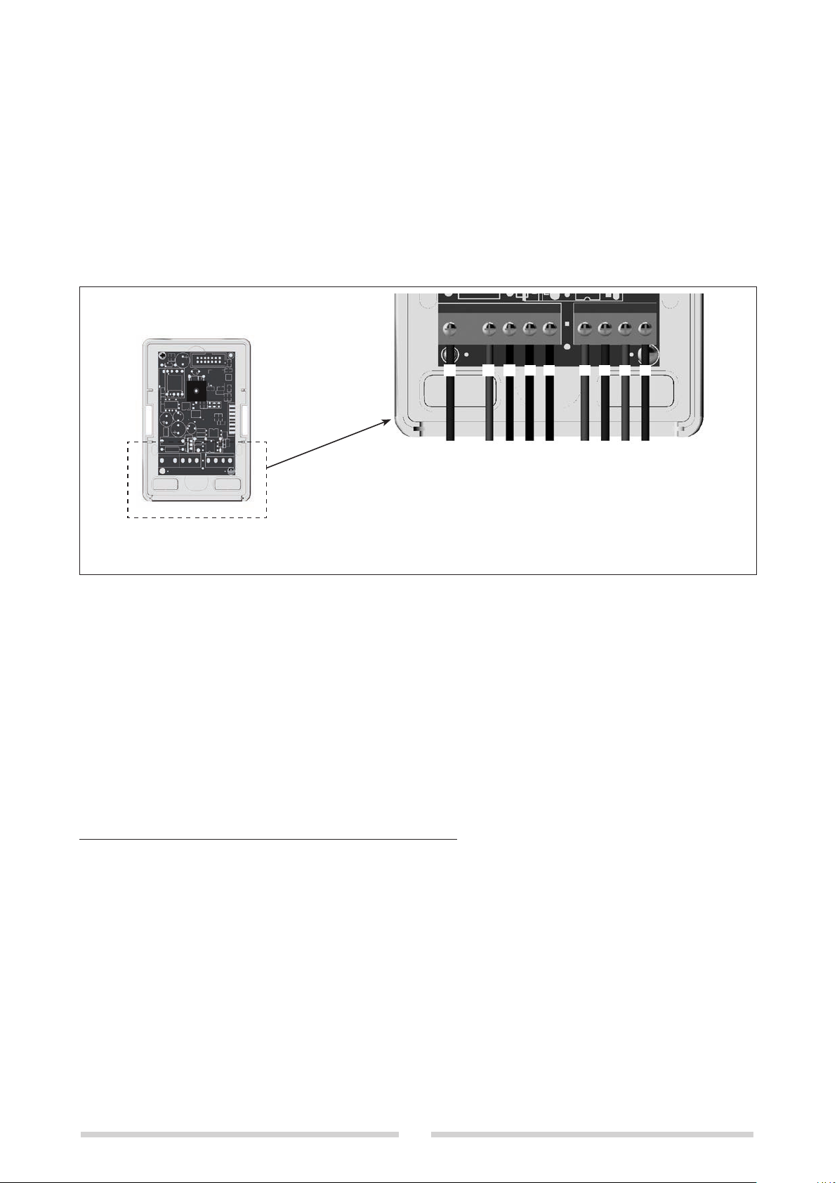
SCHÉMA BORNES DE RACCORDEMENT
A B C D E F G H I
Ligne 230 V CA
Neutre 230 V CA
Contact Relais (NO)
Contact Relais (NF)
Contact Relais (C)
Sonde S1
Sonde S2
CARACTÉRISTIQUES MÉCANIQUES
- boîtier ..........................................................................................................................................................................ABS
- couleur ................................................................................................................................................ gris clair RAL 7035
- degré d’isolation .........................................................................................................................................................IP44
- dimensions........................................................................................................... 110x77x34 mm (41 mm bouton inclus)
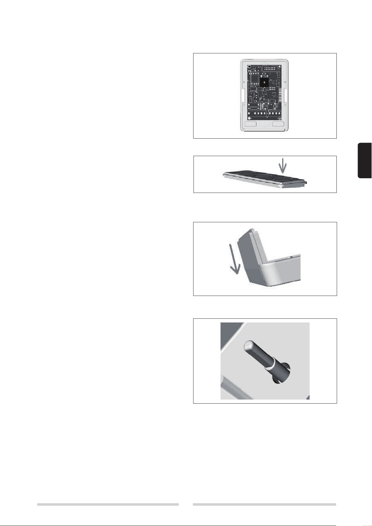
- fixation................................................................. sur mur vertical avec trous de fixation entraxe 84 mm boîte type 503*
- passage des câbles ................................................................ sur le fond de la boîte via des presse-étoupe PG7-PG9*
- température de fonctionnement........................................................................................................................10 à 60 °C
- montage.......................................................................................à la verticale, sur mur avec presse-étoupe vers le bas
* Alternatives :
On peut fixer la boîte sur le mur en utilisant, à la place des trous de fixation standard, les deux trous à entraxe de 60
mm « préparés » sur la partie inférieure du boîtier. On peut utiliser les bouchons prédécoupés sur le fond de la base de
la boîte pour le passage des câblages au lieu de faire passer ces derniers par les presse-étoupe. Dans les deux cas,
le degré d’isolation IP44 est compromis.
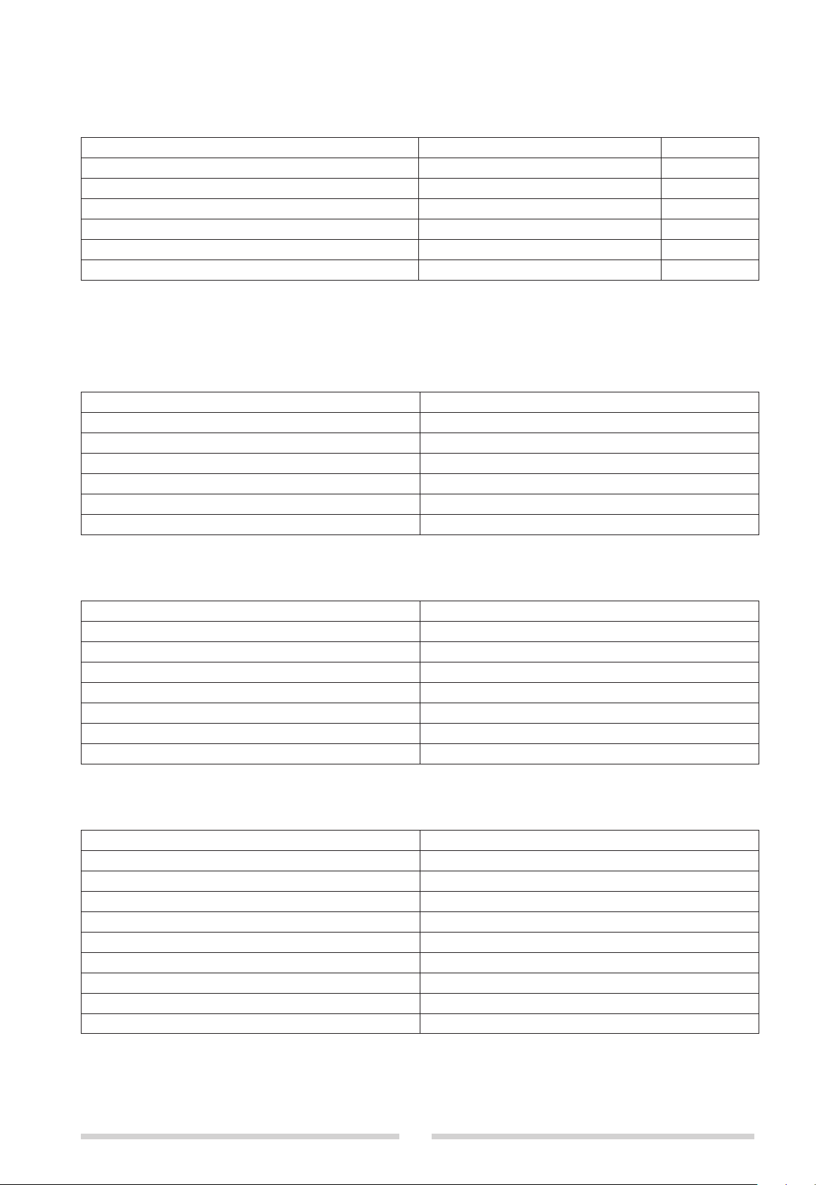
REMARQUES DE MONTAGE ET D’UTILISATION
1. L’installation doit être effectuée selon les règles de l’art par du personnel qualifié, qui devra respecter les normes en
vigueur.
2. Installer l’appareil dans une zone à l’abri des agents extérieurs et éloignée de toute source de chaleur.
3. Avant de commencer l’installation et dans tous les cas chaque fois qu’on accède à l’intérieur de la boîte, s’assurer
qu’on a bien coupé l’alimentation de réseau.
4. En cas d’interventions sur la carte, ne pas oublier de prendre toutes les précautions nécessaires afin d’éviter tout
risque de décharge électrostatique (ESD).
5. L’installation doit être protégé par des dispositifs de sécurité électrique appropriés (fusibles et/ou disjoncteurs
magnétothermiques).
6. Il est impératif de maintenir séparés les câbles conducteurs de la tension de réseau (230 V CA) du reste du
câblage, en cherchant des parcours différents.
7. Utiliser des câbles d’une section et d’une isolation adaptées au type d’utilisation.
8. Lorsqu’on enfiche ou qu’on enlève des cavaliers sur la carte, il est impératif que la carte ne soit pas alimentée.
9. Ne pas brancher ou débrancher le câblage si la carte est alimentée.
10. À l’exception des capteurs, l’appareil ne contient aucune pièce remplaçable par l’installateur.
11. Il est strictement interdit d’intervenir sur les composants ou de modifier les connexions.
12. Les capteurs de température ne peuvent être remplacés que par des capteurs ayant les mêmes caractéristiques.
13. Au terme de sa durée de vie, éliminer le produit dans un centre de tri sélectif. Ne pas le jeter dans l’environnement.

ENGLISH
11
This instruction manual is an integral part of the manual for the system in which this kit is installed. Refer to that manual
for all GENERAL SAFETY INFORMATION and PRECAUTIONS.
SUN 1 N
DIFFERENTIAL/ABSOLUTE
THERMOSTAT
APPLICATION
This device can be used as an absolute or differential thermostat.
The following are a few typical applications:
- to use a solar water heating system to help produce hot water for a central heating system (differential mode);
- to use a solar water heating system to help produce domestic hot water along with a combination boiler (absolute
mode);
- to provide frost protection (absolute mode);
- as a threshold thermostat in a low temperature system (absolute mode).
CONTENTS OF KIT
The kit comprises one cardboard box containing:
Description Qty.
Thermostat complete with control box 1
Contact type temperature sensors with cables 2
ABS screw caps for wall mounting 2
Screws + 6x30 mm wall plugs 2
PG7 type cable clamp 1
PG9 type cable clamps 2
Instruction manual 1
INSTALLATION AND CONNECTIONS
b Read the assembly and operation notes at the end
of this manual thoroughly before starting to install
the thermostat.
Make sure that the power is switched off before making
any electrical connections.
Proceed as follows to install the thermostat.
1. Open the cover by pressing a screwdriver into the
two recesses in the sides of the control box.
2. Remove the two screws holding the printed circuit
board in place.
3. Fix the base of the control box to the wall using the
screws and wall plugs provided.
b Do not overtighten the screws to avoid twisting the
base of the control box.
4. Fit the screw caps provided in the control box fixing
screw housings.

12
5. Fit the printed circuit board in the base of the control
box and fix it in place with the two screws.
6. Break off the pre-formed tabs and fit the cable
clamps to the detachable partition.
7 Wire up the printed circuit board according to the
connections table (see table 4).
8. Configure the printed circuit board by means of the
jumpers (see table 2).
9. Re-position the detachable partition with the cable
clamps inside the base of the control box. Make sure
you fit it the right way around. The bevelled edge of
the partition must face outwards towards the cover,
as shown in the figure alongside.
10. Close the box, taking care to align the cover with the
base so that the knob engages with the trimmer on
the board.
b The trimmer shaft has a flat that engages with
the knob (see figure). To make sure that the knob
engages with the trimmer on the printed circuit
board when you close the box, it is essential to
align the flat on the trimmer shaft with the corre-
sponding flat in the adjuster knob. Align the cover
over the base and gently turn the knob until you feel
it engage with the trimmer shaft. Only then push the
cover fully home on to the base.

ENGLISH
13
DIFFERENTIAL MODE
Remove jumper J2 to use the thermostat in differential mode.
Fit sensor S1 to the temperature measurement socket and fit sensor S2 to the storage cylinder.
Adjust the knob to select the desired temperature differential (∆T), within the differential mode ∆T range (2-20°C).
When the temperature measured by sensor S1 exceeds that measured by sensor S2 by a value equal to or greater
than the ∆T setpoint, the relay activates. The relay de-activates when the ∆T between the two sensors falls below the
setpoint.
In differential mode the thermostat applies a hysteresis of 3°C between the activation and deactivation of the relay.
See tables 1 and 2 for information on the signalling LED and configuration modes.
b The maximum operating temperature of the sensors is 105°C. The maximum length of the sensor cables is 20
metres.
b We recommend that you use an additional maximum temperature thermostat (which could be a second SUN1 con-
figured to operate in absolute mode) to disconnect power to the pump in the event of overtemperature. Refer to the
technical documentation provided with the storage cylinders and buffer tanks in the system for details of maximum
operating temperatures.
ABSOLUTE MODE
Fit jumper J2 to use the thermostat in absolute mode.
Only sensor S1 needs to be fitted in the temperature measurement socket.
Two temperature setpoint ranges can be selected:
With jumper J3 removed, the normal setpoint range of 40- 55°C is enabled.
With jumper J3 tted, the alternative setpoint range of 0-90°C is enabled.
First select the setpoint range you require and then turn the knob to the desired temperature setpoint.
The relay activates when the temperature measured by sensor S1 reaches the selected setpoint.
The relay de-activates when the temperature measured by sensor S1 falls below the selected setpoint.
In absolute mode, the thermostat applies a hysteresis of 3°C between the activation and deactivation of the relay.
See tables 1 and 2 for information on the signalling LED and configuration modes.
b The maximum operating temperature of the sensors is 105°C. The maximum length of the sensor cables is 20
metres.
FROST PROTECTION FUNCTION
Fit jumper J1 to enable the frost protection function.
Only sensor S1 needs to be fitted in the temperature measurement socket.
If the temperature measured by sensor S1 falls below the frost protection on threshold (5°C), the relay activates.
The relay de-activates when the temperature measured by sensor S1 reaches the frost protection off threshold (6°C).
With the thermostat configured for absolute mode and the temperature setpoint range of 0-90°C selected, the frost pro-
tection function is disabled if the knob is turned to a setpoint below the frost protection on threshold.
The frost protection function is re-enabled when the knob is turned back to a setpoint above the frost protection thresh-
old.
See table 3 for frost protection threshold values.
b The maximum operating temperature of the sensors is 105°C. The maximum length of the sensor cables is 20
metres.

14
TABLE 1 (LED SIGNALS)
FUNCTIONING STATUS FUNCTION INDICATOR RELAY STATUS
STAND-BY, DIFFERENTIAL MODE ONE FLASH, GREEN OFF
STAND-BY, NORMAL ABSOLUTE MODE ONE FLASH, GREEN OFF
STAND-BY, ALTERNATIVE ABSOLUTE MODE TWO FLASHES, GREEN OFF
ON, HEAT REQUEST ACTIVE ON, GREEN ON
STORAGE CYLINDER TEMPERATURE SENSOR ERROR FAST FLASHING, RED (*1) OFF
SOLAR TEMPERATURE SENSOR ERROR FAST FLASHING, RED (*2) ON
(*1) In absolute thermostat mode, the storage cylinder sensor is not used and ignored.
(*2) The relay is activated and the pump switched on for safety purposes.
TABLE 2 (CONFIGURATION)
FUNCTIONING MODE JUMPERS
FROST PROTECTION FUNCTION OFF J1 REMOVED
FROST PROTECTION FUNCTION ON J1 FITTED
DIFFERENTIAL THERMOSTAT J2 REMOVED
ABSOLUTE THERMOSTAT J2 FITTED
ABSOLUTE MODE NORMAL SETPOINT RANGE J3 REMOVED
ABSOLUTE MODE ALTERNATIVE SETPOINT RANGE J3 FITTED
TABLE 3 (FUNCTIONING PARAMETERS)
PARAMETER VALUE
DIFFERENTIAL MODE TEMPERATURE DIFFERENTIAL
RANGE
2-20°C
ABSOLUTE MODE NORMAL SETPOINT RANGE 40-55°C
ABSOLUTE MODE ALTERNATIVE SETPOINT RANGE 0-90°C
DIFFERENTIAL MODE HYSTERESIS 3°C
ABSOLUTE MODE HYSTERESIS 3°C
FROST PROTECTION ON THRESHOLD 5°C
FROST PROTECTION OFF THRESHOLD 6°C
TABLE 4 (ELECTRICAL CONNECTIONS)
POSITION DESCRIPTION
M1-A PHASE (230V)
M1-B NEUTRAL (230V)
M2-C N.O. RELAY
M2-D N.C. RELAY
M2-E COMMON RELAY
M3-F TEMPERATURE SENSOR 1
M3-G TEMPERATURE SENSOR 1
M3-H TEMPERATURE SENSOR 2
M3-I TEMPERATURE SENSOR 2

ENGLISH
15
ELECTRICAL CHARACTERISTICS
- Power supply ................................................................................................................................. 230VAC +/-15% 50Hz
- Sensors ..........................................contact type sensors (NTC 3KOhm @ 25°C B3977 with cable G/S 2x0.35 L=1.5 m)
- Relay output.......................................................................................................dry switching contacts, max. 5A/250Vac
- Connections................................................................................................................................screw type terminal strip
- Protection.................................................................................................................................................................... fuse
b The maximum operating temperature of the sensors is 105°C. The maximum length of the sensor cables is 20
metres.
TERMINAL STRIP CONNECTION DIAGRAM
A B C D E F G H I
Line, 230Vac
Neutral, 230Vac
Relay contact (N.O.)
Relay contact (N.C.)
Relay contact (C)
Temperature sensor S1
Temperature sensor S2
PHYSICAL CHARACTERISTICS
- Control box..................................................................................................................................................................ABS
- Colour................................................................................................................................................. RAL 7035 light grey
- Index of protection......................................................................................................................................................IP44
- Dimensions ............................................................................................. 110x77x34 mm (41 mm to outer edge of knob)
- Mounting .................................... vertical wall mounting with fixing holes at a distance of 84 mm, control box type 503*
- Cable routing ..........................................................................through base of control box, via PG7-PG9* cable clamps
- Operating temperature ........................................................................................................................................-10/60°C
- Installation............................................................................ vertical wall mounting with downward facing cable clamps
* Alternative installations:
The control box can also be fixed to the wall by means of holes in the base at a centre-to-centre distance of 60 mm
instead of the standard fixing holes. The cables can also be routed through pre-formed tabs in the base of the control
box instead of via cable clamps. If either of these alternative solutions is used, however, the IP44 protection rating is lost.
ASSEMBLY AND OPERATION NOTES
1. The thermostat must be installed in a professional manner by a qualified heating engineer, and in accordance with
applicable standards.
2. Install the thermostat where it is protected against water and dust and well away from all sources of heat.
3. Make sure the power is switched off before commencing installation and subsequently before opening the control box.
4. Follow all relevant precautions when handling the printed circuit board to avoid the risk of ESD (electrostatic dis-
charge).
5. The heating system must be protected by suitable electrical safety devices (e.g. fuses and/or magnetic thermal trip
switches).
6. Make sure that power cables (230Vac) are routed well away from signal cables.
7. Use cables of suitable size and with suitable insulation for the purpose.
8. Only fit and remove jumpers when the thermostat is powered off.
9. Never connect or disconnect cables while the thermostat is powered on.
10. The device contains no serviceable components apart from its temperature sensors.
11. It is strictly forbidden to tamper with components or modify connections.
12. Temperature sensors may only be replaced by other sensors of identical specifications.
13. Dispose of this device through an authorised waste collection centre at the end of its useful life. Do not dispose of it
into the environment.

16
Diese Anweisungen sind wesentlicher Bestandteil der Anleitung des Geräts mit dem installierten Bausatz. Für die
ALLGEMEINEN HINWEISE und die GRUNDLEGENDEN SICHERHEITSREGELN wird auf vorgenannte Anleitung verwiesen.
DIFFERENZ-/
ABSOLUTTEMPERATURREGLER
SUN 1 N
ANWENDUNG
Das Gerät ist für den Einsatz mit Funktion als Absolut-/Differenzthermostat geeignet.
Es werden nun einige Anwendungsbeispiele veranschaulicht:
- Nutzung der Solarenergie zur Unterstützung der Warmwasserbereitung für den Heizkreis (Differenzbetrieb);
- Nutzung der Solarenergie zur Unterstützung der Warmwasserbereitung mit Kombikesseln (Absolutbetrieb);
- Frostschutz (Absolutbetrieb);
- Grenzthermostat für Niedrigtemperaturanlagen (Absolutbetrieb).
INHALT DES BAUSATZES
Der Bausatz ist in einem Karton mit folgendem Inhalt
verpackt:
Beschreibung Menge
Temperaturregler mit Gehäuse 1
Kontaktfühler mit Kabel 2
ABS-Stopfen für Wandbefestigungsschrauben 2
Schrauben + Wanddübel 6x30 mm 2
Kabelverschraubung PG7 1
Kabelverschraubung PG9 2
Betriebsanleitung 1
INSTALLATION UND ANSCHLÜSSE
b Lesen Sie vor Installation des Temperaturreglers
die Einbau- und Gebrauchshinweise am Ende der
Betriebsanleitung aufmerksam durch.
Trennen Sie vor Ausführung der Anschlüsse unbedingt
die Stromversorgung.
Befolgen Sie zur einwandfreien Installation bitte folgende
Schritte:
1. Hebeln Sie den Deckel mit einem Schraubendreher
in den an den Seiten des Gehäuses eingearbeiteten
Nuten ab.
2. Nehmen Sie die zwei Befestigungsschrauben der
Leiterplatte ab.
3. Befestigen Sie die Gehäuserückseite mit den ent-
sprechenden Dübeln an der Wand.
b Achten Sie darauf, dass die Gehäuserückseite
nach der Befestigung keine Verformungen aufweist.
4. Setzen Sie die beigestellten Stopfen auf die
Befestigungsschrauben des Gehäuses.

DEUTSCH
17
5. Installieren Sie die Leiterplatte und schrauben Sie
diese an der Gehäuserückseite fest.
6. Bringen Sie die Kabelführungen nach Entfernen
der vorgestanzten Stopfen an der trennbaren
Zwischenwand an.
7 Verkabeln Sie die Leiterplatte entsprechend der
Anschlusstabelle (siehe Tabelle 4).
8. Konfigurieren Sie die Leiterplatte anhand der ent-
sprechenden Jumper (siehe Tabelle 2).
9. Achten Sie beim Einsetzen der Zwischenwand mit
den Kabelführungen in die Gehäuserückseite auf
den richtigen Einbausinn. Die abgerundete Seite der
Zwischenwand soll daher nach außen zum Deckel
gerichtet sein, siehe nebenstehende Abbildung.
10. Schließen Sie das Gehäuse und fluchten Sie den
Deckel mit der Rückseite. Führen Sie den Drehknopf
Spindel vorschriftsmäßig in das Trimmpotentiometer
auf der Leiterplatte ein.
b Die Spindel des Drehknopfs verfügt über
eine Fase als Hilfe für den richtigen Einbausinn
(siehe Abbildung). Zur einwandfreien Kopplung
der Spindel mit dem Trimmpotentiometer auf
der Leiterplatte sollten Sie beim Schließen des
Gehäuses auf die Ausrichtung der Fase mit der
Kerbe des Trimmpotentiometers achten. Heften
Sie den Deckel auf die Rückseite, drehen Sie
den Knopf solange, bis die Spindel hörbar in das
Trimmpotentiometer einschnappt, und rasten Sie
den Deckel in die Gehäuserückseite ein.

18
DIFFERENZBETRIEB
Für die Verwendung des Reglers in dieser Betriebsart darf der Jumper J2 nicht vorhanden sein.
Der Fühler S1 ist in der Erfassungshülse und der Fühler S2 im Speicher anzubringen.
Stellen Sie mit dem Drehknopf die gewünschte ∆T im ∆T Bereich des Differenzbetriebs (2-20°C) ein.
Sobald die Temperatur des Fühlers S1 die von Fühler S2 um einen Wert gleich oder größer der eingestellten ∆T über-
steigt, wird das Relais eingeschaltet. Die Abschaltung des Relais erfolgt, wenn keine ∆T zwischen den beiden Fühlern
vorliegt.
Zwischen Ein- und Ausschaltung des Relais wirkt die Hysterese des Differenzthermostats (3°C).
Für Anzeigen und Konfigurationen wird jeweils auf Tabelle 1 bzw. 2 verwiesen.
b Die max. Betriebstemperatur der Fühler beträgt 105°C, die max. Länge des Fühlerkabels 20 Meter.
b Der Einsatz eines zusätzlichen Grenzthermostats (ggf. eines zweiten SUN1 Regler mit Absolutbetrieb) wird emp-
fohlen, um die Spannungsversorgung der Pumpe bei Übertemperaturen zu trennen. Die obere Temperaturgrenze
ist aus der technischen Dokumentation von Erhitzern und Pufferspeichern ersichtlich.
ABSOLUTBETRIEB
Für die Verwendung des Reglers in dieser Betriebsart ist die Beschaltung des Jumpers J2 erforderlich.
Bei diesem Betrieb wird ausschließlich der in der Erfassungshülse installierte Fühler S1 verwendet.
Es kann mit zwei Temperatur-Sollwertbereichen gearbeitet werden:
Bei nicht vorhandenem Jumper J3 beträgt der Einstellbereich 40- 55°C.
Bei vorhandenem Jumper J3 beträgt der Einstellbereich 0-90°C.
Nachdem Sie den geeigneten Bereich erkannt haben, können Sie den gewünschten Temperatursollwert am Drehknopf
einstellen.
Die Einschaltung des Relais erfolgt, wenn die Temperatur des Fühlers S1 den gewünschten Sollwert erreicht hat.
Abgeschaltet wird das Relais, wenn die Temperatur des Fühlers S1 unter den gewünschten Sollwert abfällt.
Zwischen Ein- und Ausschaltung des Relais wirkt die Hysterese des Absolutthermostats (3°C).
Für Anzeigen und Konfigurationen wird jeweils auf Tabelle 1 bzw. 2 verwiesen.
b Die max. Betriebstemperatur der Fühler beträgt 105°C, die max. Länge des Fühlerkabels 20 Meter.
FROSTSCHUTZFUNKTION
Zur Aktivierung der Frostschutzfunktion ist die Beschaltung des Jumpers J1 erforderlich.
Bei diesem Betrieb wird ausschließlich der in der Erfassungshülse installierte Fühler S1 verwendet.
Liegt die vom Fühler S1 erfasste Temperatur unter der Einschaltschwelle der Frostschutztemperatur (5°C), wird das
Relais eingeschaltet.
Die Abschaltung des Relais erfolgt, wenn die vom Fühler S1 erfasste Temperatur die Abschaltschwelle der
Frostschutztemperatur (6°C) erreicht.
Sollte die Konfiguration Absolutthermostat mit Temperatur-Einstellbereich 0-90°C aktiviert sein und sich der eingestellte
Sollwert dem Bereich für die Auslösung der Frostschutzfunktion überlagern, schaltet sich die Frostschutzfunktion auto-
matisch aus.
Die automatische Wiedereinschaltung der Frostschutzfunktion erfolgt, sobald der Sollwert außerhalb des
Betriebsbereichs der Frostschutzfunktion eingestellt wird.
Für die Schwellenwerte der Frostschutzfunktion siehe Tabelle 3.
b Die max. Betriebstemperatur der Fühler beträgt 105°C, die max. Länge des Fühlerkabels 20 Meter.

DEUTSCH
19
TABELLE 1 (ANZEIGEN)
BETRIEBSZUSTAND LED-ANZEIGEN RELAISZUSTAND
STANDBY IM DIFFERENZBETRIEB EIN BLINKIMPULS GRÜN AUS
STANDY IM NORMALEN ABSOLUTBETRIEB EIN BLINKIMPULS GRÜN AUS
STANDBY IM ALTERNATIVEN ABSOLUTBETRIEB ZWEI BLINKIMPULSE GRÜN AUS
EIN BEI VORLIEGENDER ANFORDERUNG EIN GRÜN EIN
DEFEKT SPEICHERFÜHLER KURZER BLINKIMPULS ROT (*1) AUS
DEFEKT SOLARFÜHLER KURZER BLINKIMPULS ROT (*2) EIN
(*1) In der Konfiguration als Absolutthermostat ist der Speicherfühler nicht angeschlossen, also ignoriert.
(*2) Zwecks Sicherheit wird das Relais eingeschaltet und die Pumpe versorgt.
TABELLE 2 (KONFIGURATION)
BETRIEBSARTEN JUMPER
FROSTSCHUTZFUNKTION AUS J1 NICHT VORHANDEN
FROSTSCHUTZFUNKTION EIN J1 VORHANDEN
DIFFERENZTHERMOSTAT J2 NICHT VORHANDEN
ABSOLUTTHERMOSTAT J2 VORHANDEN
BEREICH IM NORMALEN ABSOLUTBETRIEB J3 NICHT VORHANDEN
BEREICH IM ALTERNATIVEN ABSOLUTBETRIEB J3 VORHANDEN
TABELLE 3 (BETRIEBSPARAMETER)
PARAMETER WERT
DELTA-T-BEREICH IM DIFFERENZBETRIEB 2-20°C
SOLLWERTBEREICH IM NORMALEN ABSOLUTBETRIEB 40-55°C
SOLLWERTBEREICH IM ALTERNATIVEN
ABSOLUTBETRIEB
0-90°C
HYSTERESE DELTA-T DIFFERENZBETRIEB 3°C
HYSTERESE SOLLWERT ABSOLUTBETRIEB 3°C
FROSTSCHUTZ-TEMPERATURSCHWELLE EIN 5°C
FROSTSCHUTZ-TEMPERATURSCHWELLE AUS 6°C
TABELLE 4 (STROMANSCHLÜSSE)
POSITION BESCHREIBUNG
M1-A PHASE (230V)
M1-B NULLLEITER (230V)
M2-C RELAIS MIT ARBEITSKONTAKT
M2-D RELAIS MIT RUHEKONTAKT
M2-E GEMEINSAMES RELAIS
M3-F FÜHLER 1
M3-G FÜHLER 1
M3-H FÜHLER 2
M3-I FÜHLER 2

20
ELEKTRISCHE EIGENSCHAFTEN
- Versorgung.......................................................................................................................................230Vac +/-15% 50Hz
- Sensoren....................................................Kontaktfühler (NTC 3KOhm @ 25°C B3977 und Kabel G/S 2x0,35 L=1,5 m)
- Relaisausgang .................................................................................. nicht versorgter Wechselkontakt 5 A/250Vac MAX.
- Anschlüsse.................................................................................................................................... Schraubklemmenleiste
- Schutz ................................................................................................................................................ Schmelzwiderstand
b Die max. Betriebstemperatur der Fühler beträgt 105°C, die max. Länge des Fühlerkabels 20 Meter.
ANSCHLUSSKLEMMENPLAN
A B C D E F G H I
230Vac Leitung
Nullleiter (230Vac)
Relaiskontakt (C)
Relaiskontakt (Öffner)
Relaiskontakt
Schließer)
Fühler S1
Fühler S2
MECHANISCHE EIGENSCHAFTEN
- Gehäuse......................................................................................................................................................................ABS
- Farbe....................................................................................................................................................Hellgrau RAL 7035
- Isolation ......................................................................................................................................................................IP44
- Abmessungen..............................................................................................110x77x34 mm (41 mm mitsamt Drehknopf)
- Befestigung........................senkrecht an der Wand mit Befestigungsbohrungen in 84 mm Abstand Gehäuse Typ 503*
- Kabeldurchgang......................................................................an Gehäuserückseite mittels Kabelführungen PG7-PG9*
- Betriebstemperatur ..............................................................................................................................................-10/60°C
- Einbau.......................................................................................senkrecht an der Wand mit Kabelführungen nach unten
* Varianten:
Das Gehäuse kann anhand der zwei an der Unterseite vorgerüsteten Bohrungen mit 60 mm Abstand statt mit den stan-
dardmäßigen Befestigungsbohrungen an der Wand montiert werden. Für den Kabeldurchgang in Alternative zu den
Kabelführungen können die an Rückseite vorgestanzten Stopfen verwendet werden. In beiden Fällen ist die Isolation
IP44 beeinträchtigt.
EINBAU- UND GEBRAUCHSHINWEISE
1. Die Installation hat nach einschlägiger Arbeitspraxis durch Fachpersonal gemäß den geltenden Normvorschriften zu
erfolgen.
2. Das Gerät ist an einem vor Fremdeinwirkungen geschützten Ort von Wärmequellen entfernt zu installieren.
3. Unterbrechen Sie die Stromversorgung vor der Installation und bei jedem Eingriff in das Gehäuse.
4. Beachten Sie bei der Handhabung der Leiterplatte alle erforderlichen Vorsichtsmaßnahmen, um die Gefahr elektro-
statischer Entladungen (ESD) zu vermeiden.
5. Die Anlage ist mit geeigneten elektrischen Sicherheitsvorrichtungen (Sicherungen bzw. Leitungsschutzschalter) zu
schützen.
6. Netzspannungskabel (230Vac) unbedingt von den übrigen Kabeln getrennt führen und gesondert verlegen.
7. Kabel mit auf den Einsatz abgestimmtem Querschnitt und Isolationsgrad verwenden.
8. Das Beschalten oder Trennen der Jumper auf der Leiterplatte ist unbedingt bei nicht versorgter Leiterplatte durch-
zuführen.
9. Bei versorgter Leiterplatte auf keinen Fall Kabel anschließen oder abziehen.
10. Mit Ausnahme der Sensoren beinhaltet das Gerät keine vom Installateur austauschbaren Bauteile.
11. Die Manipulation von Komponenten bzw. das Ändern von Anschlüssen ist streng verboten.
12. Die Temperatursensoren dürfen nur gegen Sensoren mit identischen Eigenschaften ersetzt werden.
13. Am Ende der Nutzdauer ist das Produkt in den Wertstoffstellen zu entsorgen und nicht in die Umwelt freizusetzen.
This manual suits for next models
1
Table of contents
Languages:
Other Beretta Thermostat manuals

Beretta
Beretta Alpha 7D Guide

Beretta
Beretta Alpha DGT User manual

Beretta
Beretta Alpha HRT-176RS User manual

Beretta
Beretta Alpha 7D User manual

Beretta
Beretta Alpha 7D Operation and installation manual

Beretta
Beretta Alpha DGT User manual

Beretta
Beretta HRT-177WS User manual

Beretta
Beretta HRT-176WS User manual

Beretta
Beretta 20050692 Guide
Popular Thermostat manuals by other brands

Cosytoes
Cosytoes TS3 installation guide

Heatcom
Heatcom atria Installation and user guide

Johnson Controls
Johnson Controls FCP-NA-701-L user guide

Owon
Owon PCT504 quick start guide

Baxi
Baxi 720644701 Installation & user's instructions

Intermatic
Intermatic InTouch Z-Wave CA8900 Installation and user instructions