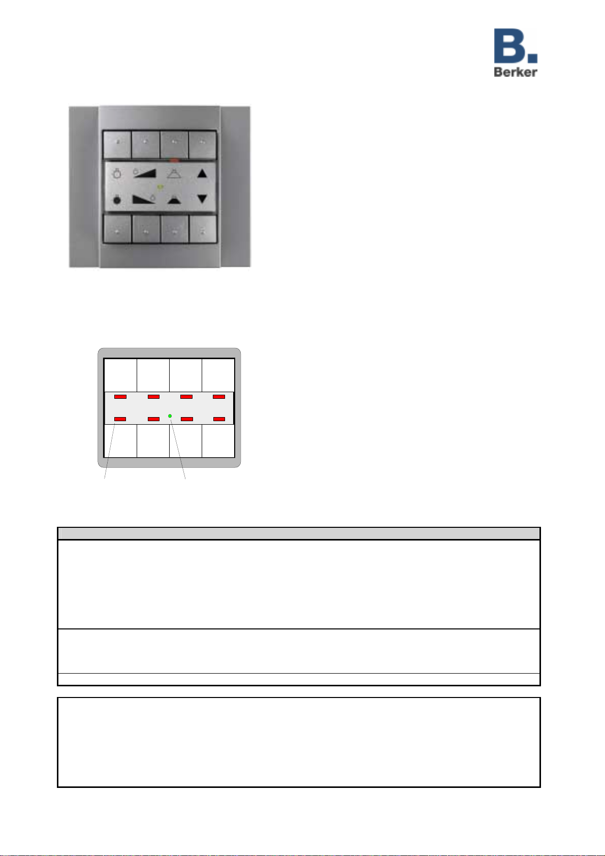
Push button comfort 1- 4gang, Flush-
mounted (Up)
751616xx, 751626xx, 751646xx
Technical
Documentation
© Gebr.Berker 2004 Act. version: 10.08.2004 Page: 4 / 23
(subject to prior change) 7516y6xx.doc Part 2
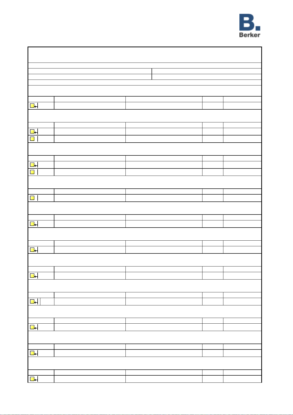
Application: PB 4-gang comfort 109002
PB 2-gang comfort 109202
PB 1-gang comfort 109302
Executable from mask version: 1.1
Number of addresses (max): 25 dynamic table handling Yes !No "
Number of assignments (max): 25 maximum lenght of table 50
Communication objects: 18
Function: Switching / Toggling (for all push-buttons
1
)
Object
2
Function Name
2
Type Flag
0-7 Switching Push-button 1 - Push-button 8 1 bit W, C, T, (R)
3
Function: Dimming (for all push-button s
1
)
Object
2
Function Name
2
Type Flag
0-7 Switching Push-button 1 - Push-button 8 1 bit W, C, T, (R)
3
8-15 Dimming Push-button 1 - Push-button 8 4 bit C, T
Function: Blind/shutter (for all push-buttons
1
)
Object
2
Function Name
2
Type Flag
0-7 Move (long-time) operation Push-button 1 - Push-button 8 1 bit W, C, T, (R)
3
8-15 Step (short-time) operation Push-button 1 - Push-button 8 1 bit C, T
Function: Value transmitter (pb function: light-scene recall with/without storage function for all pbs
1
)
Object
2
Function Name
2
Type Flag
8-15 Light-scene extension Push-button 1 - Push-button 8 1 byte C, T
Function: Value transmitter (Push-button function: value transmitter 1 byte for all push-buttons
1
)
Object
2
Function Name
2
Type Flag
8-15 Value transmitter 1 byte Push-button 1 - Push-button 8 1 byte W, C, T
Function: Value transmitter (Push-button function: temperature value transmitter for all push-buttons
1
)
Object
2
Function Name
2
Type Flag
8-15 Temperature value transmitter Push-button 1 - Push-button 8 2 bytes W, C, T
Function: Value transmitter (Push-button function: brightness value transmitter for all push-buttons
1
)
Object
2
Function Name
2
Type Flag
8-15 Brightness value transmitter Push-button 1 - Push-button 8 2 bytes W, C, T
Function: Value transmitter (Push-button function: value transmitter 2 bytes for all push-buttons
1
)
Object
2
Function Name
2
Type Flag
8-15 Value transmitter 2 bytes Push-button 1 - Push-button 8 2 bytes W, C, T
Function: Forced guidance (for all push-buttons
1
)
Object
2
Function Name
2
Type Flag
0-7 Forced guidance Push-button 1 – Push-button 8 2 bits W, C, T, (R)
3
Function: Control (for all push-buttons
1
)
Object
2
Function Name
2
Type Flag
0-7 Control Push-button 1 - Push-button 8 1 bit W, C, T, (R)
3
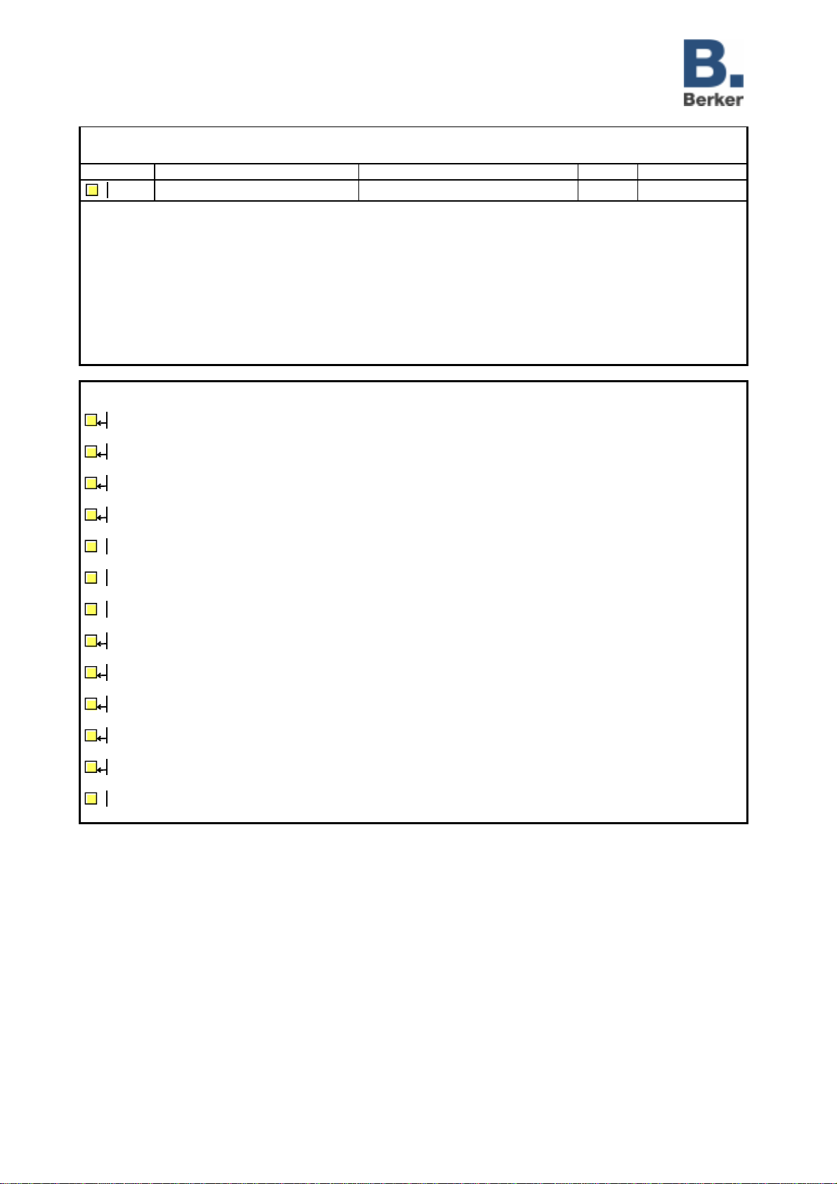
Function: Operating level switch-over
Object Function Name Type Flag
16 Switch-over Operating level 1 bit W, C, T, (R)
3