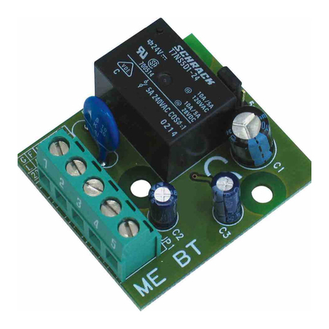
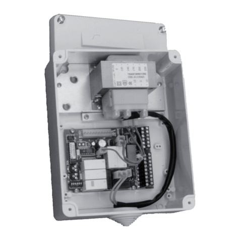
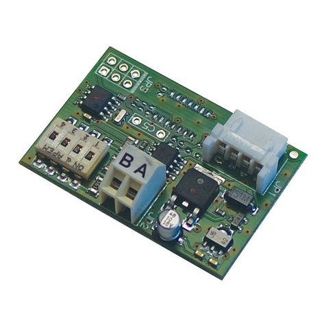
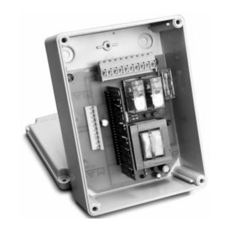
BFT ALPHA BOM User manual

D811471 ver. 05 08/04/09
I
GB
F
D
E
P
MOOVI 30-50 - ALPHA BOM
Via Lago di Vico, 44
36015 Schio (VI)
Tel.naz. 0445 696511
Tel.int. +39 0445 696533
Fax 0445 696522
Internet: www.bft.it
E-mail: [email protected]
AUTOMATISMO ELETTROMECCANICO PER BARRIERA VEICOLARE
ELECTROMECHANICAL CONTROL DEVICE FOR VEHICULAR BARRIERS
AUTOMATISME ELECTROMECANIQUE POUR BARRIERE POUR VÉHICULES
ELEKTROMECHANISHER ANTRIEB FÜR FAHRZEUGSCHRANKEN
AUTOMATISMOS ELECTROMECANICOS PARA BARRÉRAS VEHICULAR
AUTOMATIZAÇÃO ELECTROMECÂNICA PARA BARREIRA VEICULAR
8027908 2 8 0 9 2 3
ISTRUZIONI D'USO E DI INSTALLAZIONE
INSTALLATION AND USER'S MANUAL
INSTRUCTIONS D'UTILISATION ET D'INSTALLATION
MONTAGE- und BEDIENUNGSANLEITUNG
INSTRUCCIONES DE USO Y DE INSTALACION
INSTRUÇÕES DE USO E DE INSTALAÇÃO

2- MOOVI 30-50 - ALPHA BOM Ver. 05
D811471_05

MANUALE D’USO ITALIANO
Nel ringraziarVi per la preferenza accordata a questo prodotto,
la ditta è certa che da esso otterrete le prestazioni necessarie al
Vostro uso. Leggete attentamente l’opuscolo “AVVERTENZE” ed il
“LIBRETTO ISTRUZIONI” che accompagnano questo prodotto in
quanto forniscono importanti indicazioni riguardanti la sicurezza,
l’installazione, l’uso e la manutenzione. Questo prodotto risponde
alle norme riconosciute della tecnica e della disposizioni relative
alla sicurezza . Confermiamo che è conforme alle seguenti direttive
europee: 2004/108/CEE, 2006/95/CEE, 98/37/CEE (e loro modi-
che successive).
1) GENERALITÀ
Barriera elettromeccanica compatta adatta a limitare aree private,
parcheggi, accessi per uso esclusivamente veicolare. Disponibili
per passaggi da 3 a 5 metri. Finecorsa elettromeccanici regolabili,
garantiscono la corretta posizione d’arresto dell’asta. In caso di uso
intensivo, un sensore termico attiva la ventola di raffreddamento.
Lo sblocco di emergenza per la manovra manuale è comandato da
una serratura con chiave personalizzata.
L’attuatore viene sempre fornito predisposto per il montaggio a
sinistra.
In caso di necessità è comunque possibile invertire il senso di
apertura con semplici operazioni.
La base di fondazione mod. CBO (a richiesta) agevola l’installazione
della barriera.
Apposite predisposizioni facilitano l’installazione degli accessori
senza la necessità di effettuare forature.
ATTENZIONE! La barrie-
ra deve essere utilizzata esclusivamen-
te per il passaggio dei veicoli. I pedoni non devono transitare
nell’area di manovra dell’automazione. Prevedere un apposito
passaggio pedonale.
2) SBLOCCO DI EMERGENZA (Fig.1)
Lo sblocco di emergenza rende l’asta manovrabile manualmente.
Si attiva dall’esterno del cassone inserendo la chiave personaliz-
zata nella serratura posta sotto l’asta stessa e ruotandola di 180°
in senso antiorario.
ATTENZIONE: Nel caso necessiti attivare lo sblocco in un attua-
tore senza asta, assicurarsi che la molla di bilanciamento non sia
compressa (asta in posizione di apertura).
3) USO DELL’AUTOMAZIONE
Poiché l’automazione può essere comandata a distanza e quindi
non a vista, è indispensabile controllare frequentemente la perfetta
efcienza di tutti i dispositivi di sicurezza.
ATTENZIONE! Per qualsiasi anomalia di funzionamento dei dispo-
sitivi di sicurezza, intervenire rapidamente avvalendosi di personale
qualicato.
Si raccomanda di tenere i bambini a debita distanza dal campo
d’azione dell’automazione.
4) DEMOLIZIONE
L’eliminazione dei materiali va fatta rispettando le norme vigenti.
Nel caso di demolizione dell’automazione non esistono particolari
pericoli o rischi derivanti dall’automazione stessa. È opportuno, in
caso di ricupero dei materiali, che vengano separati per tipologia
(parti elettriche - rame - alluminio - plastica - ecc.).
Fig. 1
MOOVI 30-50 - ALPHA BOM Ver. 05 -3
D811471_05

USER’S MANUALENGLISH
Thank you for buying this product. Our company is sure that you
will be more than satised with the performance of the product. This
product is supplied with a “WARNINGS” leaet and an “INSTRUC-
TION MANUAL”. These should both be read carefully as they
provide important information about safety, installation, operation
and maintenance. This product complies with recognised technical
standards and safety regulations. We declare that this product is in
conformity with the following European Directives: 2004/108/CEE,
2006/95/EEC, 98/37/EEC and subsequent amendments.
1) GENERAL OUTLINE
Compactelectromechanicalbarriersuitableforlimitingprivateareas,
parkings, access areas for vehicles only.Available for passageways
from3 to 5 metres.Adjustableelectromechanical limit devicesensur-
ing a correct stop position for the boom. In case of intensive use, a
thermal sensor activates the cooling fan.
The emergency release device for manual manoeuvre is controlled
by a personalised key lock.
The actuator is always supplied for left-hand side tting.However,
when necessary, the opening direction can be reversed by means
of simple operations.
The CBO mod. foundation base (on request) makes barrier instal-
lation easier.
Appropriate ttings make it easy to install accessories without need-
ing to drill any holes.
WARNING!Thebarriermustbeexclusivelyusedforvehiclesto
drive through. Pedestrians must not walk within the opera-
tor manoeuvring area. An appropriate pedestrian passageway
must be provided for.
2) EMERGENCY RELEASE (Fig.1)
Theemergency releaseallows the bar tobe manoeuvred manually.It
is activated from the outside of the box by inserting the personalised
key into the lock placed under the bar and rotating it anticlockwise
by 180°.
WARNING! When an actuator without bar needs to be released,
ensure that the balancing spring is not compressed (bar in the
opening position).
3) USE OF AUTOMATION
As automation can be remotely controlled and therefore not within
sight, it is essential to frequently check that all safety devices are
perfectly efcient.
WARNING! In case of any malfunction in the safety devices, take
immediate action and require the assistance of a specialised tech-
nician.
It is recommended to keep children at a safe distance from the
automation eld of action.
4) SCRAPPING
Materials must be disposed of in conformity with the current regu-
lations. In case of scrapping, the automation devices do not entail
any particular risks or danger. In case of recovered materials, these
should be sorted out by type (electrical components, copper, alu-
minium, plastic etc.).
Fig. 1
4- MOOVI 30-50 - ALPHA BOM Ver. 05
D811471_05

MANUEL D’UTILISATION FRANÇAIS
Nous vous remercions pour avoir choisi ce produit. Nous sommes
certains qu’il vous offrira les performances que vous souhaitez.
Lisez attentivement
la brochure “AVERTISSEMENTS” et le “MANUEL D’INSTRUC-
TIONS” qui accompagnent ce produit, puisqu’ils fournissent d’im-
portantesindicationsconcernantlasécurité,l’installation,l’utilisation
et l’entretien. Ce produit est conforme aux règles reconnues de la
technique et aux dispositions de sécurité. Nous certions sa confor-
mité avec les directives européennes suivantes: 2004/108/CEE,
2006/95/CEE, 98/37 CEE et modications successives.
1) GENERALITES
Barrière électromécanique compacte apte pour délimiter des aires
privées, des parkings, des accès uniquement pour véhicules.
Disponible pour passages de 3 à 5 mètres. Des ns de course
électromécaniques réglables assurent la position correcte d’arrêt
de la lisse. En cas d’usage intensif, un capteur thermique active le
ventilateur de refroidissement.
Ledéblocage d’urgence pourlamanoeuvremanuelleest commandé
par une serrure avec clé personnalisée.
Le vérin est toujours fourni prédisposé pour le montage àgauche.
En cas de besoin, il est possible d’inverser la direction d’ouverture
par des simples opérations.
La plaque d’assise mod. CBO (en option) facilite l’installation de
la barrière.
Desprédispositionsspécialesfacilitentl’installationdes accessoires
sans besoin d’effectuer des perforations.
ATTENTION!Labarrièredoitêtreexclusivementutiliséepourle
passage des véhicules. Les piétons ne doivent pas passer
dans l’aire de manoeuvre de l’automation. Prévoir un passage
piétons spécial.
2) DEVERROUILLAGE D’URGENCE (Fig.1)
Le déverrouillage d’urgence permet de manoeuvrer manuellement
lisse. On l’active de l’extérieur du caisson en enfonçant la clé per-
sonnalisée dans la serrure située sous la lisse et en la tournant
de 180° dans le sens contraire àcelui des aiguilles d’une montre.
ATTENTION:S’ilse rendnécessaire d’activerledéverrouillagedans
un vérin sans lisse, s’assurer que le ressort d’équilibrage n’est pas
comprimé (lisse en position d’ouverture).
3) UTILISATION DE LA MOTORISATION
L’automationpouvantêtrecommandéeàdistance,ilestindispensable
de contrôler souvent le bon fonctionnement de tous les dispositifs
de sécurité.
ATTENTION: Pourtouteanomaliedefonctionnementdesdispositifs
de sécurité, intervenir rapidement en s’adressant àdu personnel
qualié. Il est recommandé de tenir les enfants loin du rayon d’action
de la motorisation.
4) DEMOLITION
L’élimination des matériaux doit être faite en respectant les normes
en vigueur. En cas de démolition de l’automatisme, il n’existe aucun
danger ou risque particulier dérivant de l’automatisme. En cas de
récupération de matériaux, il est opportun de les séparer selon le
genre (parties électriques - cuivre - aluminium - plastique - etc.).
Fig. 1
MOOVI 30-50 - ALPHA BOM Ver. 05 -5
D811471_05

BEDIENUNGSANLEITUNG
DEUTSCH
Wir danken für den Kauf dieses Produkts und sind sicher, daß seine
Leistungen Sie bei der von Ihnen vorgesehenenAnwendung zufrie-
denstellenwerden. Bitte lesenSie die Broschüre“WARNHINWEISE”
unddie “BEDIENUNGSANLEITUNG”, diemitder Maschinegeliefert
werden,aufmerksamdurch, da sie wichtige Hinweise zur Sicherheit,
Installierung, Anwendung und Wartung enthalten. Dieses Produkt
entspricht den anerkannten technischen und die Sicherheitsvorrich-
tungen betreffenden Vorschriften. Wir bestätigen, daß es überein-
stimmt mit den folgenden Europäischen Richtlinien: 2004/108/CEE,
2006/95/CEE, 98/37 CEE et modications successives.
1) ALLGEMEINES
Kompakte elektromechanische Schranke zur Begrenzung von
Privatgrundstücken, Parkplätzen und reinen Fahrzeugzufahrten.
Erhältlich für Wegebreiten zwischen 3 und 5 Metern. Einstellbare
elektromechanische Endschalter garantieren die korrekte Arretie-
rungsposition des Schrankenbaums. Bei Intensivnutzung aktiviert
ein Wärmefühler den Kühlungslüfter.
DieEntsperrvorrichtungfürdieHandbedienungwirddurchEinstecken
eines persönlichen Schlüssels in ein Schloß betätigt.
Der Antrieb wird stets für die linksseitige Montage vorbereitet gelie-
fert. Bei Bedarf läßt sich jedoch die Öffnungsrichtung durch einfache
Handgriffe vertauschen.
DieVerankerungsbasis CBO (aufAnfrage) erleichtert die Installation
der Schranke.
Bereits vorbereitete Aufnahmestellen erleichtern die Zubehörin-
stallation, man kommt also nicht in die Verlegenheit, Bohrungen
ausführen zu müssen.
VORSICHT!DieSchrankeistausschließlichfürdurchfahrende
Fahrzeugebstimmt. Fußgänger dürfen denAktionsbereich
der Anlage nicht passieren. Für sie ist deshalb ein eigener
Fußgängerweg vorzusehen.
2) NOTENTRIEGELUNG (Abb.1)
Die Notentriegelung ermöglicht es den Schrankenbaum von Hand
zu bewegen. Sie wird von außen am Schrankengehäuse aktiviert,
indem der im Lieferumfang enthaltene Schlüssel in das Schloß
unterhalb des Balkens eingeführt und um 180°gegen den Uhrzei-
gersinn gedreht wird.
ACHTUNG: Will man einem Schranke ohne Schrankenbaum die
Notentriegelung durchführen, ist vorher sicherzustellen, daß die
Auswuchtfeder nicht im zusammengedrückten Zustand ist (Antrieb
muss in geöffneter Position stehen).
3) BEDIENUNG DER ANLAGE
Weil dieAnlage auf Distanz und somit ohne Sichtverbindung bedient
werden kann, ist die häuge Kontrolle der perfekten Funktionsfähigkeit
aller Sicherheitseinrichtungen unerläßlich.
ACHTUNG:BeijederBetriebsstörung an den Sicherheitsvorrichtun-
gen ist schnelles Einschreiten geboten, wobei man auch Fachper-
sonal hinzuziehen sollte. Kinder sollten in gebührender Entfernung
vom Aktionsfeld der Anlage gehalten werden.
4) VERSCHROTTUNG
DieMaterialentsorgung ist unter Beachtung der geltenden Vorschrif-
ten vorzunehmen. Beim Abbau der Anlage gibt es keine von ihr
ausgehendenbesonderenGefahren oderRisiken.Es istangebracht,
die Materialarten zwecks Wiederverwertung getrennt zu sammeln
(Elektrische Teile - Kupfer - Aluminium - Plastik - etc.).
Fig. 1
6- MOOVI 30-50 - ALPHA BOM Ver. 05
D811471_05

MANUAL DE USO ESPAÑOL
Al agradecerle la preferencia que ha manifestado por este producto,
la empresa está segura de que de él obtendrá las prestaciones
necesarias para sus exigencias. Lea atentamente el folleto “AD-
VERTENCIAS” y el “MANUAL DE INSTRUCCIONES” que acom-
pañana este producto, pues proporcionan importantes indicaciones
referentes a la seguridad, la instalación, el uso y el mantenimiento
del mismo. Este producto cumple los requisitos establecidos por
las normas reconocidas de la técnica y las disposiciones relativas
a la seguridad. Conrmamos su conformidad a las siguientes
Directivas Europeas: 2004/108/CEE, 2006/95/CEE, 98/37/CEE y
modicaciones sucesivas.
1) GENERALIDADES
Barrera electromecánica compacta adecuada para limitar áreas
privadas,aparcamientos yaccesospara uso exclusivamentevehicu-
lar. Disponible para aberturas de paso de 3 a 5 metros. La correcta
posición de bloqueo del asta resulta garantizada por unos nes de
carrera electromecánicos regulables. En caso de uso intensivo, un
sensor térmico activa el ventilador de refrigeración.
El desbloqueo de emergencia para la maniobra manual se activa
por medio de una cerradura con llave personalizada.
Elservomotor sesuministra siemprepredispuestopara ser montado
a la izquierda.En caso de necesidad, es posible invertir el sentido
de apertura con extrema facilidad.
La base de cimentación mod. CBO (disponible a petición) facilita la
instalación de la barrera.
Se han previsto una serie de predisposiciones para facilitar la ins-
talación de los accesorios sin necesidad de efectuar agujeros.
¡ATENCION!Labarreradebeutilizarseexclusivamenteparael
tránsito de los vehículos. Los peatones no deben transitar
en el área de maniobra del automatismo. Es necesario prever
un pasaje peatonal especíco.
2) DESBLOQUEO DE EMERGENCIA (Fig.1)
El dispositivo de desbloqueo de emergencia permite maniobrar el
asta a mano. Se activa desde fuera de la caja, insertando la llave
personalizada en la cerradura colocada bajo el asta y dándole una
vuelta de 180° en sentido contrario a las agujas del reloj.
ATENCION! Caso de que resulte necesario activar el dispositivo
de desbloqueo en un servomotor sin asta, es preciso asegurarse
de que el muelle de equilibrio no esté comprimido (asta en posición
de apertura).
3) USO DEL AUTOMATISMO
Debido a que el automatismo puede ser accionado a distancia y,
por tanto, no a la vista, es indispensable controlar frecuentemente
la perfecta eciencia de todos los dispositivos de seguridad.
ATENCION! Ante cualquier anomalía en el funcionamiento de los
dispositivos de seguridad, intervenir rápidamente sirviéndose de
personal especializado. Se recomienda mantener a los niños fuera
del campo de acción de la automatización.
4) DEMOLICION
La eliminación de los materiales debe hacerse respetando las
normas vigentes. En el caso de demolición de un automatismo, no
existen particulares peligros o riesgos que deriven del automatismo
mismo. Es conveniente, en caso de recuperación de materiales,
que se separen por tipologías (partes eléctricas, cobre, aluminio,
plástico, etc.).
Fig. 1
MOOVI 30-50 - ALPHA BOM Ver. 05 -7
D811471_05

MANUAL PARA DE USO
PORTUGUÊS
Agradecendolhe pela preferência dada a este produto, a Empresa
tem a certeza que do mesmo obterá as prestações necessárias para
o uso que entende fazer. Leia atentamente o opúsculo “RECOMEN-
DAÇÕES” e o “ MANUAL DE INSTRUÇÕES” que o acompanham,
pois que esses fornecem indicações importantes respeitantes a
segurança, a instalação, o uso e a manutenção. Este produto está
em conformidade com as normas reconhecidas pela técnica e pelas
disposições relativas à segurança. Conrmamos que esse está em
conformidadecomasseguintesdirectivaseuropeias:2004/108/CEE,
2006/95/CEE, 98/37/CEE e modicações sucessivas.
1) GENERALIDADES
Barreiraelectromecânicacompacta,apropriadaparadelimitaráreas
privadas,parques deestacionamento,acessosparao uso exclusivo
de veículos. Disponíveis para passagens de 3 a 5 metros. Fins de
curso electromecânicos reguláveis, garantem a posição correcta de
paragem da haste. No caso de uso intensivo, um sensor térmico
activa a ventoinha de arrefecimento.
Odesbloqueiodeemergênciaparaamanobramanualécomandado
por uma fechadura com chave personalizada.
O accionador é sempre fornecido predisposto para a montagem à
esquerda.Todavia, se for necessário è possível inverter o sentido
de abertura executando algumas operações simples.
A base de fundação mod. CBO (a pedido) facilita a instalação da
barreira.
Soluções técnicas especiais facilitam a instalação dos acessórios
sem que seja necessário efectuar furos.
ATENÇÃO!Abarreiradeveserutilizadaexclusivamenteparaa
passagem dos veículos. Os peões não devem transitar
pela zona de manobra do automatismo. Prever uma passagem
especicadamente para peões.
2) DESBLOQUEIO DE EMERGÊNCIA (Fig.1)
O desbloqueio de emergência consente de manobrar manualmente
a haste. Activa-se do exterior da caixa metálica, inserindo a chave
personalizadana fechaduracolocada por baixoda haste e girando-a
de 180° no sentido contrário aos ponteiros do relógio.
ATENÇÃO: Caso seja necessário activar o desbloqueio num accio-
nador sem haste, assegure-se que a mola de equilíbrio não esteja
comprimida (haste na posição de abertura).
3) USO DA AUTOMATIZAÇÃO
Dado que a automatização pode ser comandada à distância, por
meiodeum radiocomando ou botão de start, e portanto não é visível,
é indispensável controlar frequentemente a perfeita eciência de
todos os dispositivos de segurança.
ATENÇÃO! Para qualquer anomalia de funcionamento dos dispo-
sitivos de segurança, intervir rapidamente valendo-se também de
pessoal qualicado. Recomenda-se de manter as crianças à devida
distância do raio de acção da automatização.
4) DEMOLIÇÃO
Aeliminação dos materiais deve ser feita respeitando-se as normas
vigentes. No caso de demolição da automatização não existem
particulares perigos ou riscos que derivem da própria automati-
zação. É oportuno, no caso de recuperação dos materiais, que
os mesmos sejam separados por tipo (partes eléctricas - cobre
- alumínio - plástico - etc.).
Fig. 1
8- MOOVI 30-50 - ALPHA BOM Ver. 05
D811471_05

MANUALE PER L’INSTALLAZIONE ITALIANO
Nel ringraziarVi per la preferenza accordata a questo prodotto,
la ditta è certa che da esso otterrete le prestazioni necessarie al
Vostro uso. Leggete attentamente l’opuscolo “AVVERTENZE” ed il
“LIBRETTO ISTRUZIONI” che accompagnano questo prodotto in
quanto forniscono importanti indicazioni riguardanti la sicurezza,
l’installazione, l’uso e la manutenzione. Questo prodotto risponde
alle norme riconosciute della tecnica e della disposizioni relative
alla sicurezza . Confermiamo che è conforme alle seguenti direttive
europee: 2004/108/CEE, 2006/95/CEE, 98/37/CEE (e loro modiche
successive).
1) GENERALITÀ
Barriera elettromeccanica compatta adatta a limitare aree private,
parcheggi, accessi per uso esclusivamente veicolare. Disponibili
per passaggi da 3 a 5 metri. Finecorsa elettromeccanici regolabili,
garantiscono la corretta posizione d’arresto dell’asta. In caso di uso
intensivo, un sensore termico attiva la ventola di raffreddamento.
Lo sblocco di emergenza per la manovra manuale è comandato da
una serratura con chiave personalizzata.
L’attuatore viene sempre fornito predisposto per il montaggio a
sinistra.
In caso di necessità è comunque possibile invertire il senso di
apertura con semplici operazioni.
La base di fondazione mod. CBO (a richiesta) agevola l’installazione
della barriera.
Apposite predisposizioni facilitano l’installazione degli accessori
senza la necessità di effettuare forature.
2) SICUREZZA GENERALE
ATTENZIONE! Una installazione errata o un uso improprio del
prodotto, può creare danni a persone, animali o cose.
• Leggete attentamente l’opuscolo ”Avvertenze” ed il ”Libretto
istruzioni”cheaccompagnanoquestoprodotto, inquantofornisco-
no Importanti indicazioni riguardanti la sicurezza, l’installazione,
l’uso e la manutenzione.
• Smaltire i materiali di imballo (plastica, cartone, polistirolo, ecc.)
secondo quanto previsto dalle norme vigenti. Non lasciare buste
di nylon e polistirolo a portata dei bambini.
• Conservare le istruzioni per allegarle al fascicolo tecnico e per
consultazioni future.
• Questo prodotto è stato progettato e costruito esclusivamente
per l’utilizzo indicato in questa documentazione.
Usi non indicati in questa documentazione potrebbero essere
fonte di danni al prodotto e fonte di pericolo.
• La Ditta declina qualsiasi responsabilità derivante dall’uso
improprio o diverso da quello per cui è destinato ed indicato
nella presente documentazione.
• Non installare il prodotto in atmosfera esplosiva.
• Gli elementi costruttivi della macchina devono essere in accordo
con le seguenti Direttive Europee: 2004/108/CEE, 2006/95/CEE,
98/37/CEE (e loro modiche successive). Per tutti i Paesi extra
CEE, oltre alle norme nazionali vigenti, per un buon livello di
sicurezza è opportuno rispettare anche le norme sopracitate.
•
LaDittadeclinaqualsiasiresponsabilitàdall’inosservanzadellaBuona
Tecnicanellacostruzionedellechiusure(porte,cancelli,ecc.),nonché
dalle deformazioni che potrebbero vericarsi durante l’uso.
• L’installazione deve essere in accordo con quanto previsto dalle
Direttive Europee: 2004/108/CEE, 2006/95/CEE, 98/37/CEE (e
loro modiche successive).
• Togliere l’alimentazione elettrica, prima di qualsiasi intervento
sull’impianto. Scollegare anche eventuali batterie tampone se
presenti.
• Prevedere sulla rete di alimentazione dell’automazione, un inter-
ruttore o un magnetotermico onnipolare con distanza di apertura
dei contatti uguale o superiore a 3,5 mm.
• Vericare che a monte della rete di alimentazione, vi sia un
interruttore differenziale con soglia da 0.03A.
• Vericare se l’impianto di terra è realizzato correttamente: colle-
gare tutte le parti metalliche della chiusura (porte, cancelli, ecc.)
e tutti i componenti dell’impianto provvisti di morsetto di terra.
• Applicare tutti i dispositivi di sicurezza (fotocellule, coste sensibili,
ecc.) necessari a proteggere l’area da pericoli di schiacciamento,
convogliamento, cesoiamento, secondo ed in conformità alle
direttive e norme tecniche applicabili.
• Applicare almeno un dispositivo di segnalazione luminosa (lam-
peggiante) in posizione visibile, ssare alla struttura un cartello di
Attenzione.
• La Ditta declina ogni responsabilità ai ni della sicurezza e del
buon funzionamento dell’automazione se vengono impiegati
componenti di altri produttori.
• Usare esclusivamente parti originali per qualsiasi manutenzione
o riparazione.
• Non eseguire alcuna modica ai componenti dell’automazione
se non espressamente autorizzata dalla Ditta.
• Istruire l’utilizzatore dell’impianto per quanto riguarda i sistemi di
comando applicati e l’esecuzione dell’apertura manuale in caso
di emergenza.
• Non permettere a persone e bambini di sostare nell’area d’azione
dell’automazione.
• Non lasciare radiocomandi o altri dispositivi di comando alla
portata dei bambini onde evitare azionamenti involontari dell’au-
tomazione.
• L’utilizzatore deve evitare qualsiasi tentativo di intervento o ripara-
zione dell’automazione e rivolgersi solo a personale qualicato.
• Tutto quello che non è espressamente previsto in queste istruzioni,
non è permesso.
• L’installazione deve essere fatta utilizzando dispositivi di sicurezza
e comandi conformi alla EN 12978.
3) DATI TECNICI
MOOVI 30-50
Alimentazione:...............................................230V~±10% 50Hz (*)
Potenza assorbita:.................................................................300W
Motore: ................................................................. 1400 min-1 4 poli
Condensatore:......................8µF 450V (230V): 32µF 250V (110V)
Assorbimento:............................................................... 1.4 A: 2.8 A
Classe isolamento: ....................................................................... F
Temperatura intervento ventilazione:...........110 °C (avvolgimento)
Temperatura intervento disgiuntura:............ 130 °C (autoripristino)
Lubricazione riduttore: ...................................Grasso permanente
Coppia max: ........................MOOVI-30 85Nm: MOOVI-50 250Nm
Tempo apertura: ............................. MOOVI-30 4 s: MOOVI-50 8 s
Lunghezza asta (alluminio):MOOVI-30 3m max.: MOOVI-50 5m max.
Reazione all’urto (costa sensibile): Arresto o arresto ed inversione
Finecorsa:...................................... Elettrici incorporati e regolabili-
Manovra manuale:.................................... Sblocco rapido a chiave
N° manovre in 24h:................1200-(MOOVI-30): 600-(MOOVI-50)
Temperatura di esercizio: .......................................-10°C ÷ +55 C°
Grado di protezione:................................................................IP24
Peso attuatore (senza asta): ................................ 356N (~35,6 kg)
Dimensioni:.................................................................. Vedere g.1
QUADRO COMANDO ALPHA BOM
Alimentazione:...............................................230V~±10% 50Hz (*)
Assorbimento a vuoto:........................................................ 100 mA
Uscita alim. accessori:.......................................24V~ 200 mA max
Potenza max. motore: ...........................................................500W
Finecorsa:............................................................................elettrici
Tempo di lavoro: ...............................................................10s MAX
Temperatura di utilizzo:...........................................-10°C ÷ +55 C°
(*)Tensioni speciali di alimentazione a richiesta.
4) ACCESSORI OPZIONALI (Fig.17)
- Base di fondazione CBO
- Kit protezione cesoiamento KIT MOOVI PRM
- Kit colonnina ssaggio Cellula 130 KIT MOOVI 130
- Forcella ssa per appoggio asta FAF
- Gamba mobile per appoggio asta MOOVI GA (Solo MOOVI 50)
- Gamba mobile ammortizzata per appoggio asta MOOVI GAMA
- Siepe già assemblata all’asta SB
MOOVI 30-50 - ALPHA BOM Ver. 05 -9
D811471_05

MANUALE PER L’INSTALLAZIONE
ITALIANO
- Costa sensibile BIR
- Kit luci per aste da 3m a 4,5m KIT MOOVI LIGHT
- Kit luci per aste da 5m o 6m KIT MOOVI LIGHT 1
- Prolo di copertura inferiore o superiore asta MOOVI PCA
Perulterioriinformazionicircal’installazioneel’utilizzodegliaccessori
fate riferimento al rispettivo manuale istruzione.
5) PIASTRA DI FONDAZIONE (Fig.2)
- Predisporre uno scavo di fondazione adeguato al tipo di terre-
no.
- Predisporre più canalette per il passaggio dei cavi elettrici.
- Posizionare le viti in dotazione con la base mod. CBO nei 4 fori
di ssaggio con il letto rivolto verso l’alto. Saldare le teste delle
4 viti alla base e proteggere le saldature con antiruggine. Posi-
zionare la base in modo che sporga di circa 20mm dal pavimento
(g.2).
- Riempire di calcestruzzo lo scavo, controllando la posizione della
base in entrambi i sensi con livella e lasciare che il cemento
rapprenda.
6) MONTAGGIO ATTUATORE
ATTENZIONE!Labarrieradeveessereutilizzataesclusivamen
teperilpassaggiodeiveicoli.Ipedoninondevonotransitare
nell’area di manovra dell’automazione. Prevedere un apposito
passaggio pedonale.
Il passaggio deve essere opportunamente evidenziato con i
segnali d’obbligo evidenziati in Fig.10.
ATTENZIONE: prima di aprire lo sportello la molla deve essere
scarica (asta a 43°). Lo sportello del cassone deve essere rivolto
dal lato interno della proprietà. Ponendosi in mezzo al passaggio,
se il cassone è a sinistra, la barriera è sinistra: se il cassone è a
destra la barriera è destra.
L’attuatore viene sempre fornito predisposto per il montaggio a
sinistra.
6.1) Montaggio sinistro
- Fissare l’attuatore alla base di fondazione bloccandolo con dadi
M12 (g.4/rif.1). Lo sportello del cassone deve essere rivolto dal
lato interno della proprietà.
- La supercie superiore dell’attuatore risulta leggermente inclinata
in modo da impedire ristagni di acqua piovana. Utilizzare pertanto
una supercie laterale per controllare con la livella il corretto
posizionamento (g.2).
- L’installazione del Kit anticesoiamento MOOVI PRM (opzionale)
risulta più agevole se effettuata prima del montaggio dell’asta
sull’automazione.
Fate riferimento alla Fig.18 e al paragrafo 6.3 per il corretto
montaggio del Kit MOOVI PRM, successivamente procedere al
montaggio dell’asta.
- Montare l’asta in posizione di apertura (verticale) come indicato
in “g.3/rif.7”. L’attuatore viene fornito con il bilanciamento tarato
per l’asta nominale ed in posizione di apertura (molla di bilan-
ciamento allungata).
- Posizionare sull’asta la chiusura della copertura “g.3 rif.10” come
indicato in g. 3. Una volta in posizione forare part.10 e asta con
punta da 2 mm. Inserire la vite in dotazione.
- Fissare l’asta utilizzando la staffa “g.3 rif.4” mediante le viti e le
rondelle fornite in dotazione, successivamente ssare la copertura
“g.3 rif.8” e quindi applicare il coperchio “g.3 rif.9”. Chiudere
la copertura di protezione facendo scorrere sull’asta la chiusura
“g.3 rif.10”.
ATTENZIONE! L’asta dovrà essere posizionata in modo che il
doppio prolo sia rivolto verso il basso “g.3 rif.11”.
- Bilanciare l’asta come descritto al rispettivo paragrafo 7.
6.2) Montaggio destro
Necessita spostare alcuni organi interni facendo riferimento alla
g.4 ed operando come di seguito descritto.
A) Fissare il cassone alla base di fondazione bloccandolo con i dadi
M12.
B) Accertarsi che la molla di bilanciamento sia in posizione di aper-
tura (molla allungata - g.5).
C) Allentare completamente il tendimolla “g.4/rif.2” no a permettere
di togliere la vite “g.4/rif.3” che lo ancora al fondo del cassone.
D)
Togliere la staffa bloccaggio asta “g.4/rif.4” ed allentare la vite
“g.4/rif.5” con chiave a tubo CH19 no a permettere la rotazione
della leva “g.4/rif.6”.
E) Ruotare la leva “g.4/rif.6” di 180° e incastrarla in posizione corretta.
F) Serrare il tirante “g.4/rif.5” che blocca la leva “g.4/rif.6” con
chiave dinamometrica regolata ad una coppia di circa 80 Nm.
G) Portare la chiave di sblocco (g.6) in posizione di funzionamento
manuale e ruotare manualmente la leva “g.4/rif.6” verso il bas-
so per 90° (g.7) in modo da portare la barriera in posizione di
apertura destra.
H) Bloccare il tendimolla “g.4/rif.2” nella posizione “g.4/rif.Dx” con
la vite e il dado autobloccante.
I) Regolare il tendimolla “g.4/rif.2” no a mettere in tensione la
molla.
L) Rimontare e ssare parzialmente il cavallotto “g.4/rif.4” che ssa
l’asta all’attuatore in posizione di apertura.
M)L’installazione del Kit anticesoiamento MOOVI PRM (opzionale)
risulta più agevole se effettuata prima del montaggio dell’asta
sull’automazione.
Fate riferimento alla Fig.18 e al paragrafo 6.3 per il corretto
montaggio del Kit MOOVI PRM, successivamente procedere al
montaggio dell’asta. Montare l’asta in posizione di apertura
(verticale) come indicato in “g.3/rif.7”. L’attuatore viene fornito
con il bilanciamento tarato per l’asta nominale ed in posizione di
apertura (molla di bilanciamento allungata).
Posizionare sull’asta la chiusura della copertura “g.3 rif.10” come
indicato in g. 3. Una volta in posizione forare part.10 e asta con
punta da 2 mm. Inserire la vite in dotazione.
Fissare l’asta utilizzando la staffa “g.3 rif.4” mediante le viti e le ron-
delle fornite in dotazione, successivamente ssare la copertura “g.3
rif.8” e quindi applicare il coperchio “g.3 rif.9”. Chiudere la copertura
di protezione facendo scorrere sull’asta la chiusura “g.3 rif.10”.
ATTENZIONE! L’asta dovrà essere posizionata in modo che il
doppio prolo sia rivolto verso il basso “g.3 rif.11”.
N) Eseguire il bilanciamento dell’asta come indicato al paragrafo 7.
O) Nel quadro di comando (g.15-16), invertire i collegamenti dei ne
corsa ed i collegamenti di marcia del motore facendo riferimento
alle istruzioni del quadro di comando presente. In g.8, è riportato
uno schema che evidenzia i collegamenti da invertire.
6.3) Montaggio kit anticesoiamento MOOVI PRM (Fig.18)
1) Rimuovere i tappi di gomma.
2) Unire i due perni “P” alla piastra anticesoiamento “L” in modo da
ottenere un corpo unico.
3) Fissare nel foro lettato centrale, utilizzando la vite M6x20, la
piastra al cassone.
4) Fissare la vite di blocco rotazione M6x20 sul foro lettato laterale.
5) La piastra anticesoiamento andrà posizionata dal lato di apertura
dell’asta, la vite di blocco sul foro che rimane libero.
6) Nel successivo montaggio della copertura la piastra deve trovarsi
inserita tra i due perni di guida “D” ssati con le viti C.
Al termine del montaggio vericare il corretto funzionamento della
piastra anticesoiamento. A barriera alzata deve trovarsi nella posi-
zione indicata in Fig.18 rif.7, durante la chiusura la piastra dovrà
seguire il movimento dell’asta no a portarsi nella posizione indicata
in Fig. 18 rif.8.
6.4) Montaggio lampeggiante LAMPO/LAMPO-PA (FIG.19)
L’installazione del lampeggiante si effettua utilizzando una delle due
predisposizioni superiori della barriera MOOVI. E’ indispensabile
utilizzare la staffa di ssaggio SLM2. Si consiglia inoltre di predi-
sporre il lampeggiante sul anco della barriera opposto al verso di
apertura dell’asta.
Facendo riferimento alla Fig.19 procedere come segue:
1) Rimuovere la copertura “C” di protezione posta sulla barriera.
2) Rimuovere la copertura “D” dalla staffa SLM2.
10 - MOOVI 30-50 - ALPHA BOM Ver. 05
D811471_05

MANUALE PER L’INSTALLAZIONE ITALIANO
3) Dopo aver predisposto i cablaggi di connessione al lampeggiante s-
sare la staffa SLM2 alla barriera utilizzando le apposite viti (fornite).
4) Il distanziale “E” è necessario solo per il lampeggianti della serie
“PA”(predispostiperl’antennaricevente).Perilampeggiantisenza
antenna ssare direttamente la base alla staffa SLM2.
5) Riposizionare la copertura “D”.
6) Completare il montaggio ed il cablaggio come indicato nelle
istruzioni LAMPO/LAMPO-PA.
6.5) Montaggio Fotocellule (FIG.20)
L’installazione della fotocellula sulla barriera MOOVI si può effettuare:
1- Fissando direttamente la fotocellula CELLULA 130 sul anco
della barriera (Fig.20 “A”).
2- Montando la colonnina fotocellula MOOVI 130 su una delle
predisposizioni frontali (Fig.20 ”B”).
A) Montaggio Cellula 130
1) Rimuovere la copertura di protezione posta sulla barriera.
2) Predisporre i cablaggi necessari alla connessione della fotocel-
lula.
3) Applicare la fotocellula come indicato in Fig. 20 A utilizzando le
apposite viti.
Fate riferimento al foglio istruzioni Cellula 130 per ulteriori infor-
mazioni.
B) Montaggio colonnina MOOVI 130
1) Rimuovere la copertura di protezione posta sulla barriera.
2) Predisporre i cablaggi necessari alla connessione della fotocellula.
3) Applicare la colonnina “F” e la cornice di protezione “G” come
indicato in Fig.20B.
Il ssaggio avviene dall’interno della barriera utilizzando 3 viti
(fornite).
4) Applicare la fotocelulla alla colonnina come indicato nel foglio
istruzioni Cellula 130.
Fate riferimento al foglio istruzioni Cellula 130 per ulteriori infor-
mazioni.
6.6) Accessori Moovi: limiti lunghezza asta e bilanciamento
(Fig.21)
Tutte le barriere della serie MOOVI dispongono di una staffa di
aggancio con 3 punti di ssaggio del dispositivo di bilanciamento
asta (Fig. 21 - rif.A punti A-B-C).
A seconda del tipo di barriera, della lunghezza dell’asta e degli
accessori installati è necessario individuare il punto di ssaggio
ottimale per un corretto bilanciamento dell’asta.
La Tab.1 di Fig.21 riporta per ogni accessorio il peso espresso in
Kg per metro lineare (kg/m).
Nelcasodiutilizzodellagamba diappoggio MooviGA/GAMAoccorre
calcolare il peso ttizio in Kg/m, utilizzando questa formula:
Kg/m = 1,2/L
dove L è la lunghezza dell’asta.
Procedere quindi come segue:
1) Sommare il peso lineare complessivo degli accessori installati
(compreso quello dell’asta).
2) Individuare nel diagramma corrispondente al modello di MOOVI
utilizzato il punto di incrocio tra lunghezza dell’asta e peso com-
plessivo degli accessori.
3)
Il punto cadrà in un’area indicante il punto di aggancio corretto
(A-B-C).
Esempio
MOOVI 50 con:
(asta da 4,0m + BIR + GAMA +1PCA).
(1,028+0,510+(1,2/4,0)+0,160)= 1,97
Il punto di incrocio tra il valore 1,97 e la lunghezza asta 4,0 cade
nell’area “A” del graco MOOVI 50. Il punto di aggancio “A” consentirà
pertanto il corretto bilanciamento dell’asta.
Procedere alla taratura della molla come indicato nel paragrafo 7.
ATTENZIONE!:
I punti di ssaggio A e B sono utilizzabili solo con MOOVI 50.
Il punto di ssaggio C è utilizzabile solo con MOOVI 30.
Se il punto cade nell’area barrata l’installazione non è possibile, è
necessario accorciare l’asta o ridurre il numero degli accessori.
Se non si utilizzano accessori utilizzare il solo peso dell’asta “PA”
per individuare il punto di ssaggio.
7) BILANCIAMENTO ASTA (Fig.9)
- Attivare lo sblocco di emergenza (g.14).
- Posizionare l’asta a circa 45° (g.9). L’asta deve rimanere ferma.
- Se l’asta tende ad aprire, scaricare la molla agendo nel tirante “T”.
- Se l’asta tende a chiudersi, caricare la molla agendo nel tirante “T”.
In entrambi i casi, caricare o scaricare la molla no a quando
l’asta rimane ferma a circa 45°.
- Ripristinare il funzionamento motorizzato ruotando la chiave di
sblocco nel verso opposto (g.14).
ATTENZIONE: Durante la manovra di chiusura, la molla di bilancia-
mento non deve mai andare a pacco (completamente compressa).
In g.9 è indicata la posizione di rilevamento della misura minima
che può raggiungere la molla compressa con l’asta in posizione di
apertura (verticale).
8) PREDISPOSIZIONE DELL’IMPIANTO ELETTRICO
ATTENZIONE: prima di aprire lo sportello la molla deve es-
sere scarica (asta a 43°). Predisporre l’impianto elettrico (g.10)
facendo riferimento alle norme vigenti per gli impianti elettrici CEI
64-8, IEC364, armonizzazione HD384 ed altre norme nazionali.
Tenere nettamente separati i collegamenti di alimentazione di rete
dai collegamenti di servizio (fotocellule, coste sensibili, dispositivi
di comando ecc.).
ATTENZIONE! Per il collegamento alla rete, utilizzare cavo
multipolare di sezione minima 3x1.5mm2e del tipo previsto
dalle normative precedentemente citate (a titolo di esempio
se il cavo non è protetto deve essere almeno pari a H07 RN-F
mentre se protetto deve essere almeno pari a H05 VV-F con
sezione 3x1.5 mm2).
Realizzare i collegamenti dei dispositivi di comando e di sicurezza
in armonia con le norme per l’impiantistica precedentemente citate.
In g.10 è riportato il numero di collegamenti e la sezione per una
lunghezza dei cavi di alimentazione di 100 metri; per lunghezze
superiori, calcolare la sezione per il carico reale dell’automazione.
Quando le lunghezza dei collegamenti ausiliari superano i 50 metri o
passanoinzonecriticheperidisturbi,èconsigliatoildisaccopiamento
dei dispositivi di comando e di sicurezza con opportuni relè.
I componenti principali per una automazione sono (g.10):
I) Interruttore onnipolare omologato di adeguata portata con
apertura contatti di almeno 3,5 mm provvisto di protezione
contro i sovraccarichi ed i corto circuiti, atto a sezionare
l’automazionedallarete.Installarea montedell’automazione,
se non già presente, un interruttore onnipolare omologato
con soglia 0,03A.
QR) Quadro comando e ricevente incorporata.
S) Selettore a chiave.
AL) Lampeggiante con antenna accordata.
M) Attuatore.
A) Asta.
F) Forcella d’appoggio.
CS) Costa sensibile.
CC) Controllo costa.
Ft,F) Coppia fotocellule.
CF) Colonnina fotocellule.
T) Trasmittente 1-2-4 canali.
9) COLLEGAMENTI MORSETTIERA
ATTENZIONE: prima di aprire lo sportello la molla deve essere
scarica (asta a 43°). Passati gli adeguati cavi elettrici nelle cana-
lette e ssati i vari componenti dell’automazione nei punti prescelti,
si passa al loro collegamento secondo le indicazioni e gli schemi
riportati nel manuale istruzioni del quadro. Effettuare la connessione
della fase, del neutro e della terra (obbligatoria). Il conduttore di
protezione (terra) con guaina isolante di colore giallo/verde, deve
essere collegato negli appositi morsetti previsti e contrassegnati
dal simbolo. Evitare nel modo più assoluto di mettere in funzione
MOOVI 30-50 - ALPHA BOM Ver. 05 -11
D811471_05

l’automazione priva di protezioni. Ciò è pregiudizievole ai ni della
sicurezzapersonaleedelprodottostesso.Inognicasol’automazione
non deve essere messa in funzione prima di avere eseguito tutti i
collegamenti e vericato l’efcienza dei dispositivi di sicurezza.
Tenere i collegamenti in bassa tensione nettamente separati dai
collegamenti di alimentazione di rete.
JP1
1-2 Alimentazione 230V +/- 10% 50/60 Hz (Neutro al morsetto 1).
3-4-5 Collegamento motore M (morsetto 4 comune, morsetti 3-5
marcia motore e condensatore).
1-4 Collegamento lampeggiante 230V.
JP2
7-8 IngressoSTARToselettoreachiave(N.O.)contrimmerTW=max.
Ingresso OPEN (N.O.) con trimmer TW=min.
7-9 Pulsante STOP (N.C.). Se non si utilizza lasciare ponticellato.
7-10 Ingresso fotocellula o costa pneumatica (N.C.). Se non si
utilizza lasciare ponticellato.
7-11 Fine corsa di apertura (N.C.). Se non si utilizza lasciare ponti-
cellato.
7-12 Fine corsa di chiusura (N.C.). Se non si utilizza lasciare pon-
ticellato.
13-14 Uscita 24 V~per alimentazione fotocellula ed altri dispositivi.
15-16 Uscita per spia cancello aperto / 2° canale radio
17-18 Ingresso antenna ricevente (17 segnale, 18 calza)
JP3
19-20 Ingresso PEDONALE (N.O.) con trimmer TW=max.
Ingresso CLOSE (N.O.) con trimmer TW=min.
JP4 Connettore scheda radioricevente 1-2 canali.
In g.7 è rappresentato uno schema generale di collegamento.
9.1) LED (Fig.16)
Le centraline ALPHA-ALPHA BOM sono provviste di una serie di
Leds di autodiagnosi che consentono il controllo di tutte le funzioni.
Le funzioni dei led sono le seguenti:
DL1:Led radio ricevitore incorporato
DL2:START (trimmer TW=max) - si accende al comando di START
OPEN (trimmer TW=min) - si accende al comando di OPEN
DL3:STOP - si spegne al comando di Stop.
DL4:PHOT - si spegne con fotocellule non allineate o in presenza di
ostacoli.
DL5: SWO - si spegne al comando necorsa apertura.
DL6: SWC - si spegne al comando necorsa chiusura.
9.2) SELEZIONE DIP-SWITCH (Fig.16)
DIP1)TCA [ON] - Tempo di chiusura automatica.
ON: Chiusura automatica inserita.
OFF: Chiusura automatica esclusa.
DIP2)FCH [ON] - Fotocellule.
ON: Fotocellule attive solo in chiusura.
OFF: Fotocellule attive in chiusura ed apertura.
DIP3)BLI - Blocca impulsi.
ON: Durante la fase di apertura non accetta i comandi di START.
OFF: Durante la fase di apertura accetta i comandi di START.
DIP4)3P/4P - 3 passi o 4 passi.
ON: Abilita la logica 3 passi.
OFF: Abilita la logica 4 passi.
DIP5)CODE FIX - Codice sso.
ON: Attiva la ricevente incorporata in modalità codice sso.
OFF: Attiva la ricevente incorporata in modalità rolling-code.
DIP6)RADIO LEARN - Programmazione radiocomandi.
ON: Abilita la memorizzazione via radio dei trasmettitori:
1 - Premere in sequenza il tasto nascosto (P1) ed il tasto
normale (T1-T2-T3-T4) di un trasmettitore già memorizzato
in modalità standard attraverso il menù radio.
2 - Premere entro 10s il tasto nascosto (P1) ed il tasto normale
T1-T2-T3-T4) di un trasmettitore da memorizzare.
La ricevente esce dalla modalità programmazione dopo 10s,
entro questo tempo è possibile inserire ulteriori nuovi trasmet-
titori.
Questa modalità non richiede l’accesso al quadro di comando.
MANUALE PER L’INSTALLAZIONE
ITALIANO
OFF: Disabilita la memorizzazione via radio dei trasmettitori.
I trasmettitori vengono memorizzati solo tramite programma-
zione manuale.
DIP7)SCA - Spia cancello aperto o 2° canale radio.
OFF: Attiva l’uscita relé in modalità Spia cancello aperto.
ON: Attiva l’uscita relé come 2° canale radio.
DIP8)FAST CLOSE
ON: Chiude il cancello dopo il disimpegno delle fotocellule prima
di attendere il termine del TCA impostato.
OFF: Comando non inserito.
9.3) REGOLAZIONE TRIMMER (Fig.16)
TCA (Dip-Fix TCA in ON).
Regola il tempo di chiusura automatica, trascorso il quale, la barriera
si chiude automaticamente (regolabile da 0 a 90sec).
TW
Il tempo di lavoro è ssato a 10s.
Trimmer TW = min: gli ingressi 7-8 e 19-20 sono considerati rispet-
tivamente come ingressi OPEN e CLOSE.
Trimmer TW = max: gli ingressi 7-8 e 19-20 sono considerati rispet-
tivamente come ingressi START e PEDONALE.
9.4) ACCESSORI
SS (g.6).
Scheda opzionale spia cancello aperto. Funziona solamente con
necorsa elettrici.
10) DATI TECNICI RICEVITORE INTEGRATO
Canali di uscita della ricevente:
- Canale uscita1, se reso attivo comanda uno START.
- Canale uscita 2, se reso attivo comanda l’eccitazione del relè II°
canale radio per 1s.
Versioni trasmettitori utilizzabili:
Tutti i trasmettitori ROLLING CODE compatibili con .
INSTALLAZIONE ANTENNA
Usare una antenna accordata sui 433MHz.
Per il collegamento Antenna-Ricevitore usare cavo coassiale RG58.
La presenza di masse metalliche a ridosso dell’antenna, può distur-
bare la ricezione radio. In caso di scarsa portata del trasmettitore,
spostare l’antenna in un punto più idoneo.
11) PROGRAMMAZIONE
Lamemorizzazionedeitrasmettitoripuòavvenireinmodalitàmanuale
o a mezzo del programmatore palmare universale, che consente la
realizzazione di installazioni nella modalità “comunità di ricevitori”
e la gestione tramite il software EEdbase del database completo
dell’installazione.
12) PROGRAMMAZIONE MANUALE
Nel caso di installazioni standard nelle quali non siano richieste le
funzionalità avanzate è possibile procedere alla memorizzazione
manuale dei trasmettitori.
1) Se si desidera che il tasto T della trasmittente sia memorizzato
come start premere il pulsante SW1 nella centralina oppure se si
desidera che il tasto T della trasmittente sia memorizzato come
secondo canale radio, premere il pulsante SW2 nella centralina.
2) Al lampeggio del Led DL1 premere il tasto nascosto P1 del tra-
smettitore, il Led DL1 resterà acceso sso.
3) Premere il tasto da memorizzare del trasmettitore, il led DL1
ricomincerà a lampeggiare.
4) Per memorizzare un ulteriore trasmettitore ripetere i passi 2) e 3).
5) Per uscire dal modo di memorizzazione attendere no al completo
spegnimento del led.
NOTAIMPORTANTE: CONTRASSEGNAREILPRIMOTRASMET-
TITORE MEMORIZZATO CON IL BOLLINO CHIAVE (MASTER).
Ilprimotrasmettitore,nelcasodiprogrammazionemanuale,assegna
il codice chiave al ricevitore; questo codice risulta necessario per
poter effettuare la successiva clonazione dei radiotrasmettitori.
12 - MOOVI 30-50 - ALPHA BOM Ver. 05
D811471_05

MANUALE PER L’INSTALLAZIONE ITALIANO
12.1) CANCELLAZIONE MEMORIA CENTRALINA
Percancellaretotalmentela memoriadellacentralina premerecontem-
poraneamente per 10 secondi i pulsanti SW1 e SW2 nella centralina
(il led DL1 lampeggia). La corretta cancellazione della memoria sarà
segnalata dal Led DL1 acceso sso. Per uscire dal modo di memo-
rizzazione attendere no al completo spegnimento del led.
13) CONFIGURAZIONE RICEVITORE
Il ricevitore a bordo di tipo clonabile unisce le caratteristiche di
estrema sicurezza alla copiatura della codica a codice variabile
(rolling code), la praticità di poter effettuare, grazie ad un esclusivo
sistema, operazioni di “clonazione” di trasmettitori.
Clonare un trasmettitore signica generare un trasmettitore in grado di
inserirsi automaticamente nella lista dei trasmettitori memorizzati nel
ricevitore aggiungendosi o sostituendo un particolare trasmettitore.
La clonazione per sostituizione consente di creare un nuovo tra-
smettitore che prende il posto nel ricevitore di un trasmettitore
precedentemente memorizzato, in questo sarà possibile rimuovere
dalla memoria e rendere non più utilizzabile un trasmettitore.
Saràquindipossibileprogrammarea distanzaesenzainterveniresul
ricevitoreun gran numerodi trasmettitoriinaggiunta o insostituzione
di trasmettitori che, per esempio, siano stati smarriti.
Quando la sicurezza della codica non sia determinante, il ricevitore
a bordo permette di effettuare la clonazione in aggiunta a codice sso
che, rinunciando al codice variabile, permette comunque di avere
una codica con un elevato numero di combinazioni, mantenendo
la possibilità di “copiare” un qualsiasi ricevitore già programmato.
14) CLONAZIONE DEI RADIOTRASMETTITORI (g.7)
Clonazione con rolling code/Clonazione a codice sso
Fateriferimentoalleistruzionidelprogrammatorepalmareuniversale
e alla Guida programmazione CLONIX.
14.1) PROGRAMMAZIONE AVANZATA: COMUNITÀ DI RICEVITORI
Fateriferimentoalleistruzionidelprogrammatorepalmareuniversale
e alla Guida programmazione CLONIX.
15) REGOLAZIONE FINECORSA
ATTENZIONE: prima di aprire lo sportello la molla deve essere
scarica (asta a 43°). La barriera dispone di necorsa elettrici e di
arresto meccanico a necorsa. Tra ne corsa elettrico ed arresto
meccanico deve rimanere un margine di rotazione (circa 1°) sia in
chiusura che in apertura (g.11).
La regolazione si effettua come segue.
- Attivare lo sblocco manuale, portare l’asta in completa apertura
(posizione perfettamente verticale).
- Manualmente anticipare l’asta di circa 2° rispetto alla verticale.
-
Regolare il micro di apertura (g.12 rif.SWO) allentando il grano (g.13
rif.G) e spostando la camma (g.13 rif.C) no a percepire lo scatto
del micro (o vericare che il rispettivo led del quadro si spenga).
- Portare manualmente l’asta in completa chiusura ed in appoggio
nella forcella (g.11 rif.F), controllare con una livella (g.11 rif.L)
che l’asta sia perfettamente orizzontale).
- Regolare il micro di chiusura (g.12 rif.SWC) allentando il grano
(g.13 rif.G) e spostando la camma (g.13 rif.C) no a percepire
lo scatto del micro (o vericare che il rispettivo led del quadro si
spenga).
- Regolare il micro di chiusura (g.12 rif.SWC) in modo che arresti l’asta
qualche millimetro prima che batta nella forcella (g.11 rif.F).
- Attivare il funzionamento motorizzato ed eseguire alcuni cicli.
- Vericare che il necorsa elettrico arresti l’asta prima che rag-
giunga la verticale in apertura.
- Vericare che il necorsa elettrico arresti l’asta prima che si
appoggi nella forcella “F” in chiusura.
- Eventualmente ritoccare le posizioni delle camme “C” (g.13)
che comandano i necorsa.
16) SBLOCCO DI EMERGENZA (Fig.14)
Lo sblocco di emergenza rende l’asta manovrabile manualmente.
Si attiva dall’esterno del cassone inserendo la chiave personaliz-
zata nella serratura posta sotto l’asta stessa e ruotandola di 180°
in senso antiorario.
ATTENZIONE: Nel caso necessiti attivare lo sblocco in un attua-
tore senza asta, assicurarsi che la molla di bilanciamento non sia
compressa (asta in posizione di apertura).
17) USO DELL’AUTOMAZIONE
Poiché l’automazione può essere comandata a distanza e quindi
non a vista, è indispensabile controllare frequentemente la perfetta
efcienza di tutti i dispositivi di sicurezza.
ATTENZIONE! Per qualsiasi anomalia di funzionamento dei dispositivi di
sicurezza, intervenire rapidamente avvalendosi di personale qualicato.
Si raccomanda di tenere i bambini a debita distanza dal campo
d’azione dell’automazione.
18) COMANDO
L’utilizzodell’automazioneconsenteil controllodell’accesso inmodo
motorizzato. Il comando può essere di diverso tipo ( manuale - te-
lecomando- controllo accessi con badge magnetico - rilevatore di
presenza ecc.) secondo le necessità e le caratteristiche dell’installa-
zione. Per i vari sistemi di comando, vedere le istruzioni relative.
19) MANUTENZIONE
ATTENZIONE: prima di aprire lo sportello la molla deve essere
scarica (asta a 43°). ATTENZIONE! Per qualsiasi manutenzione
all’installazione, togliere l’alimentazione di rete. I punti che necessi-
tano di controlli e manutenzione sono:
- Le ottiche delle fotocellule se presenti. Eseguire saltuariamente
la pulizia.
- Costa sensibile. Periodicamente, controllare manualmente che
la costa arresti l’asta in caso di ostacolo.
- Ogni due anni, smontare il motoriduttore e sostituire il grasso lubri-
cante.
- Per qualsiasi anomalia di funzionamento riscontrata, e non risolta,
togliere l’alimentazione di rete e richiedere l’intervento di personale
qualicato (installatore). Per il periodo di fuori servizio dell’automa-
zione,attivare lo sblocco di emergenza(vediparagrafo “11”)in modo
da rendere libera l’apertura e la chiusura manuale dell’asta.
20) DEMOLIZIONE
L’eliminazione dei materiali va fatta rispettando le norme vigenti.
Nel caso di demolizione dell’automazione non esistono particolari
pericoli o rischi derivanti dall’automazione stessa. È opportuno, in
caso di ricupero dei materiali, che vengano separati per tipologia
(parti elettriche - rame - alluminio - plastica - ecc.).
21) SMANTELLAMENTO
ATTENZIONE: prima di aprire lo sportello la molla deve essere
scarica (asta a 43°). Nel caso l’automazione venga smontata per
essere poi rimontata in altro sito bisogna:
- Togliere l’alimentazione e scollegare tutto l’impianto elettrico.
- Togliere l’attuatore dalla base di ssaggio.
- Smontare tutti i componenti dell’installazione.
- Nelcasoalcuni componentinonpossanoessererimossio risultino
danneggiati, provvedere alla loro sostituzione.
22) MALFUNZIONAMENTO. CAUSE e RIMEDI.
22.1) L’asta non apre. Il motore non gira.
ATTENZIONE: prima di aprire lo sportello la molla deve essere
scarica (asta a 43°).
1) Vericare che fotocellule non siano sporche, o impegnate, o non
allineate.
Procedere di conseguenza. Vericare la costa sensibile.
2)
Se il motore è surriscaldato, può essere intervenuta la protezione
termica.
Attendere l’autoripristino.
3) Vericare il corretto collegamento del motore e del condensatore
di marcia.
4) Vericare che l’apparecchiatura elettronica sia regolarmente ali-
mentata. Vericare l’integrità dei fusibili.
MOOVI 30-50 - ALPHA BOM Ver. 05 -13
D811471_05

5) Mediantei ledsdidiagnosi delquadro(vedererispettiveistruzioni),
controllaresele funzionisonocorrette.Individuare eventualmente
la causa del difetto. Se i leds indicano che persiste un comando di
start, controllare che non vi siano radiocomandi, pulsanti di start
o altri dispositivi di comando che mantengono attivato (chiuso) il
contatto di start.
6) Se il quadro non funziona, sostituirlo.
7) Vericare il movimento delle astine portacamma (Fig.13), se il
movimento non risultasse uido, provvedere alla loro lubrica-
zione.
22.2) L’asta non apre. Il motore gira ma non avviene il movimento.
1) Lo sblocco manuale è rimasto inserito. Ripristinare il funziona-
mento motorizzato.
2) Se lo sblocco e in posizione di funzionamento motorizzato, veri-
care l’integrità del riduttore.
AVVERTENZE
Il buon funzionamento dell’operatore è garantito solo se ven-
gono rispettate i dati riportati in questo manuale. La ditta non
risponde dei danni causati dall’inosservanza delle norme di
installazione e delle indicazioni riportate in questo manuale.
Le descrizioni e le illustrazioni del presente manuale non sono
impegnative. Lasciando inalterate le caratteristiche essenziali
del prodotto, la Ditta si riserva di apportare in qualunque mo-
mento le modiche che essa ritiene convenienti per migliorare
tecnicamente,costruttivamenteecommercialmenteilprodotto,
senza impegnarsi ad aggiornare la presente pubblicazione.
MANUALE PER L’INSTALLAZIONE
ITALIANO
14 - MOOVI 30-50 - ALPHA BOM Ver. 05
D811471_05

Thank you for buying this product. Our company is sure that you
will be more than satised with the performance of the product. This
product is supplied with a “WARNINGS” leaet and an “INSTRUC-
TION MANUAL”. These should both be read carefully as they
provide important information about safety, installation, operation
and maintenance. This product complies with recognised technical
standards and safety regulations. We declare that this product is in
conformity with the following European Directives: 2004/108/CEE,
2006/95/EEC, 98/37/EEC and subsequent amendments.
1) GENERAL OUTLINE
Compactelectromechanicalbarriersuitableforlimitingprivateareas,
parkings, access areas for vehicles only.Available for passageways
from3 to 5 metres.Adjustable electromechanical limit devices ensur-
ing a correct stop position for the boom. In case of intensive use, a
thermal sensor activates the cooling fan.
The emergency release device for manual manoeuvre is controlled
by a personalised key lock.
The actuator is always supplied for left-hand side tting.However,
when necessary, the opening direction can be reversed by means
of simple operations.
The CBO mod. foundation base (on request) makes barrier instal-
lation easier.
Appropriate ttings make it easy to install accessories without need-
ing to drill any holes.
2) GENERAL SAFETY
WARNING! An incorrect installation or improper use of the
product can cause damage to persons, animals or things.
• The “Warnings” leaet and “Instruction booklet” supplied with
this product should be read carefully as they provide important
information about safety, installation, use and maintenance.
• Scrap packing materials (plastic, cardboard, polystyrene etc)
according to the provisions set out by current standards. Keep
nylon or polystyrene bags out of children’s reach.
• Keep the instructions together with the technical brochure for
future reference.
• This product was exclusively designed and manufactured for the
use specied in the present documentation. Any other use not
specied in this documentation could damage the product and
be dangerous.
• The Company declines all responsibility for any consequences
resultingfromimproperuseof theproduct,or usewhichisdifferent
from that expected and specied in the present documentation.
• Do not install the product in explosive atmosphere.
• The construction components of this product must comply with
thefollowingEuropean Directives:2004/108/CEE,2006/95/EEC,
98/37/EEC and subsequent amendments. As for all non-EEC
countries, the above-mentioned standards as well as the cur-
rent national standards should be respected in order to achieve
a good safety level.
• The Company declines all responsibility for any consequences
resulting from failure to observe Good Technical Practice when
constructing closing structures (door, gates etc.), as well as from
any deformation which might occur during use.
• The installation must comply with the provisions set out by the
following European Directives: 2004/108/CEE, 2006/95/EEC,
98/37/EEC and subsequent amendments.
• Disconnect the electrical power supply before carrying out any work
on the installation. Also disconnect any buffer batteries, if tted.
• Fit an omnipolar or magnetothermal switch on the mains power
supply, having a contact opening distance equal to or greater
than 3,5 mm.
• Check that a differential switch with a 0.03A threshold is tted
just before the power supply mains.
• Check that earthing is carried out correctly: connect all metal
parts for closure (doors, gates etc.) and all system components
provided with an earth terminal.
• Fit all the safety devices (photocells, electric edges etc.) which are
neededtoprotectthearea from any danger caused by squashing,
conveying and shearing, according to and in compliance with the
applicable directives and technical standards.
• Position at least one luminous signal indication device (blinker) where
it can be easily seen, and x a Warning sign to the structure.
• The Company declines all responsibility with respect to the auto-
mation safety and correct operation when other manufacturers’
components are used.
• Only use original parts for any maintenance or repair opera-
tion.
• Do not modify the automation components, unless explicitly
authorised by the company.
• Instruct the product user about the control systems provided and
the manual opening operation in case of emergency.
• Do not allow persons or children to remain in the automation
operation area.
• Keep radio control or other control devices out of children’s reach,
in order to avoid unintentional automation activation.
• The user must avoid any attempt to carry out work or repair on
the automation system, and always request the assistance of
qualied personnel.
• Anything which is not expressly provided for in the present instruc-
tions, is not allowed.
• Installation must be carried out using the safety devices and
controls prescribed by the EN 12978 Standard.
3) TECHNICAL SPECIFICATIONS
MOOVI 30-50
Power supply:................................................230V~±10% 50Hz (*)
Absorbed power: ...................................................................300W
Motor: ............................................................... 1400 min-1, 4 poles
Capacitor: .............................8µF 450V (230V) :32µF 250V (110V)
Absorption: ................................................................... 0.8 A :1.6 A
Insulation class:............................................................................ F
Ventilation intervention temperature:..................... 110°C (winding)
Circuit-breaker intervention temperature:..... 130°C (self-resetting)
Reduction gear lubrication:................................Permanent grease
Max torque:..........................MOOVI-30 85Nm: MOOVI-50 250Nm
Opening time: .................................. MOOVI-30 4s : MOOVI-50 8s
(Aluminium) bar length: MOOVI-30 3m max : MOOVI-50 5m max.
Impact reaction (electric edge): ............... Stop or stop and reverse
Limiting devices:................... Electric, incorporated and adjustable
Manual manoeuvre:............................................Quick key release
No. manoeuvres in 24 hour: .. 1200 (MOOVI-30) :600 (MOOVI-50)
Working temperature:..............................................-10°C ÷ +55°C
Degree of protection:...............................................................IP24
Actuator weight (without bar):............................... 356N (~35.6 kg)
Dimensions:...................................................................... See g.1
ALPHA BOM CONTROL PANEL
Power supply: ...............................................230V~±10% 50Hz (*)
Loadless absorption: ......................................................... 100 mA
Accessory output power: ..................................24V~ 200 mA max
Max. motor power absorbed: ................................................500W
Limits switch: ............................................................ electric switch
Working time:...................................................................10 s MAX
Working temperature: ...................................................-10 +55 °C
(*) Special power voltages available on request.
4) OPTIONAL ACCESSORIES (Fig.17)
- CBO. Foundation base
- MOOVI PRM. Antishearing Kit
- MOOVI 130. Kit for Cellula 130 xing post
- FAF. Fixed fork for boom rest
- MOOVI GA. Movable rod for boom rest (Only for MOOVI 50)
- MOOVI GAMA. Movable cushioned rod for boom rest
- SB. Skirt already assembled to the boom
- Safety edge BIR
- MOOVI LIGHT. Light kit for booms from 3m to 4.5m
- MOOVI LIGHT 1. Light kit for booms from 5m to 6m
- MOOVI PCA. Lower or upper boom covering contour
INSTALLATION MANUAL ENGLISH
MOOVI 30-50 - ALPHA BOM Ver. 05 -15
D811471_05

INSTALLATION MANUAL
ENGLISH
For further information about installation and use of the accessories,
make reference to their respective instruction manuals.
5) FOUNDATION PLATE (Fig.2)
- Prepare a foundation hole suitable for the particular kind of
ground.
- Layout several raceways for the electric cables to pass through.
- Position the screws supplied with the CBO mod. base into the
4 xing holes with the thread facing upwards. Weld the 4 screw
heads to the base and protect the welds with rust preventer.
Position the base so that it protrudes about 20mm from the oor
(g.2).
- Fill the hole with concrete, checking the position of the base in
both directions by means of a level, and let the cement harden.
6) FITTING OF THE ACTUATOR
WARNING!Thebarriermustbeexclusivelyusedforvehiclesto
drive through. Pedestrians must not walk within the opera-
tor manoeuvring area. An appropriate pedestrian passageway
must be provided for.
The passageway must be suitably indicated by means of the
warning signs illustrated in Fig.10.
WARNING: before opening the door, make sure that the spring
has been unloaded (rod at 43°). The door of the box must face
the inside of the property. When standing in the middle of the pas-
sageway, if the box is on the left the barrier opens to the left, and if
the box is on the right the barrier opens to the right.
The barrier is available with the operator tted either to the left (look-
ing from the door side) or to the right.
The actuator is always supplied for left-hand side tting.
6.1) Left-hand tting
- Fix the operator to the foundation base and secure it by means of
nuts M12 (g.4 ref.1). The door of the box must face towards the
inside of the property.
- The upper surface of the operator is slightly tilted so as to prevent
any rain water from being trapped there. Therefore use a side
surface to check correct positioning by means of a level (g.2).
- The installation of the MOOVI PRM antishearing Kit (optional) is
easier when carried out before tting the boom to the operator.
Make reference to Fig.18 and paragraph 6.3 for correct tting of
the MOOVI PRM Kit, then proceed to t the boom.
- Fit the boom in its opening position (vertical) as indicated in g.3,
ref.7. The operator balancing is pre-calibrated for the nominal
boom in the opening position (balancing spring stretched).
- Position the cover closing element (g.3 ref.10) on the boom, as
indicated in g. 3. After positioning, drill part 10 and boom using
a 2 mm bit. Insert the screw supplied.
- Fix the boom using the bracket (g.3 ref.4) and the screws and wash-
ers supplied as standard, then x the protection cover (g.3 ref.8)
and nally the screw cover (g.3 ref.9). Close the protection cover
by making the closing element slide over the boom (g.3 ref.10).
WARNING!The boom must be positioned so as to have the
double contour facing down (g.3 ref.11).
- Balance the boom as described in relevant paragraph 7.
6.2) Right-hand tting
Some internal members need to be moved, with reference to g. 4
and the following procedure:
A) Fix the box to the foundation base and lock it in position using M12
nuts.
B) Ensure that the balancing spring is in the opening position
(stretched spring - g.5).
C) Completely slacken the spring stretcher (g.4/ref. 2) until the
screw (g. 4/ref.3) anchoring it to the bottom of the box can be
removed.
D) Remove the bar locking bracket (g.4/ref.4) and slacken the screw
(g. 4/ref.5) by means of a CH19 socket spanner until the lever
can be rota-ted (g.4/ref.6).
E)
Rotate the lever (g.4/ref.6) by 180° and fasten it into the correct
position.
F) Tighten the tie rod (g. 4/ref.5) blocking the lever (g.4/ref.6) by
means of a torque wrench set at about 80 N/m.
G) Bring the release key (g.6) to the manual operation position and
manually rotate the lever (g.4/ref.6) downwards by 90° (g.7) so
as to bring the barrier to the right-hand opening position.
H) Lock the spring stretcher (g.4/ref.2) into position (g.4/ref.Dx)
with the screw and self-locking nut.
I) Adjust the spring stretcher (g.4/ref.2) until the spring comes
under tension.
L) Ret and partially x the U bolt (g.4/ref.4) holding the bar to the
actuator in the opening position.
M)The installation of the MOOVI PRM antishearing Kit (optional) is
easier when carried out before tting the boom to the operator.
Make reference to Fig.18 and paragraph 6.3 for correct tting of
the MOOVI PRM Kit, then proceed to t the boom. Fit the boom
in its opening position (vertical) as indicated in g.3, ref.7. The
operator balancing is pre-calibrated for the nominal boom in the
opening position (balancing spring stretched).
Position the cover closing element (g.3 ref.10) on the boom, as
indicated in g. 3. After positioning, drill part 10 and boom using
a 2 mm bit. Insert the screw supplied.
Fix the boom using the bracket (g.3 ref.4) and the screws and wash-
ers supplied as standard, then x the protection cover (g.3 ref.8)
and nally the screw cover (g.3 ref.9). Close the protection cover
by making the closing element slide over the boom (g.3 ref.10).
WARNING! The boom must be positioned so as to have the
double contour facing down (g.3 ref.11).
N) Carry out bar balancing as described in paragraph 7.
O) Invertthelimit switch connections and themotordrive connections
inside the control unit (g.15-16), with reference to the instruc-
tions regarding the existing control unit. Fig.8 shows a diagram
highlighting the connections to be inverted.
6.3) Fitting of MOOVI PRM antishearing Kit (Fig.18)
1) Remove the rubber plugs.
2) Join two pivots “P” to antishearing plate “L” so as to obtain a single
body.
3) Fix the plate to the box by putting screw M6x20 through the central
threaded hole in the box.
4) Fix rotation lock screw M6x10 through the side threaded hole in
the box.
5) The antishearing plate is to be positioned on the boom opening,
the lock screw through the remaining hole.
6) During subsequent tting of the cover, the plate must be inserted
between two guide pivots “D” xed by means of screws C.
Having completed the tting procedure, check that the antishear-
ing plate operates correctly. When the barrier is lifted, it must be
in the position indicated in Fig.18, ref.7; when the barrier is being
closed, the plate must follow the boom movement until it reaches
the position indicated in Fig.18, ref.8.
6.4) LAMPO/LAMPO-PA blinker tting (Fig. 19)
Blinker installation is carried using one of the two upper ttings
on the MOOVI barrier. It is indispensable to use the SLM2 xing
bracket. It is also recommended to install the blinker on the side of
the barrier opposite to the boom opening direction.
Making reference to Fig. 19, proceed as follows:
1) Remove protection cover “C” positioned on the barrier.
2) Remove cover “D” from the SLM” bracket.
3) Having laid the connection cables to the blinker, x the SLM2 bracket
to the barrier by means of the appropriate screws (supplied).
4) Spacer “E” is only necessary for the “PA” series blinkers (suitable
for the receiver antenna). For blinkers without antennas, the base
is to be directly xed to the SLM2 bracket.
5) Reposition cover “D”.
6) Complete tting and wiring as specied in the instructions for
LAMPO/LAMPO-PA.
16 - MOOVI 30-50 - ALPHA BOM Ver. 05
D811471_05

6.5) Photocell tting (Fig. 20)
The photocell can be installed on the MOOVI barrier as follows:
1- By directly xing the CELLULA 130 photocell to the side of the
barrier (Fig. 20 “A”)
2- By fastening the MOOVI 130 photocell post to one of the front
ttings (Fig. 20 ”B”)
A) Cellula 130 tting
1) Remove the protection cover positioned on the barrier.
2) Lay the wiring needed for photocell connection.
3) Fit the photocell as shown in Fig. 20 A by means of the appropri-
ate screws.
Refer to the instruction sheet for Cellula 130 for further information.
B) MOOVI 130 post tting
1) Remove the protection cover positioned on the barrier.
2) Lay the wiring needed for photocell connection.
3) Fit post “F” and protection frame “G” as shown in Fig. 20B.
The post is fastened from inside the barrier by means of 3 screws
(supplied).
4) Fit the photocell to the post, as shown in the instruction sheet for
Cellula 130.
Refer to the instruction sheet for Cellula 130 for further information.
6.6)Moovi accessories: boom length limits and balancing (Fig.21)
All barriers belonging to the MOOVI series are equipped with a
hooking bracket with 3 securing points located on the device for
boom balancing (Fig. 21 - ref. A points A-B-C).
The ideal securing point for correct balancing of the boom must be
chosen according to the barrier type and to the length of the boom
and accessories installed.
Tab.1 of Fig.21 shows the weight expressed in kgs by linear meter
(kg/m) for each accessory.
When the supporting leg Moovi GA/GAMAis used, it is necessary to
calculate the arbitrary weight in Kg/m, using the following formula:
Kg/m = 1,2/L
where L stands for the length of the boom.
Then proceed as follows:
1) Sum up the total linear weight of the accessories installed (includ-
ing boom weight).
2) Find the crossing point between the length of the boom and the
total weight of the accessories on the diagram, making reference
to the MOOVI model.
3) The point found in this way will indicate the correct hooking point
(A-B-C).
Example
MOOVI 50 with:
(boom measuring 4,0m + BIR + GAMA +1PCA).
(1,028+0,510+(1,2/4,0)+0,160)= 1,97
The crossing point between value 1,97 and boom length equal to
4,0 is within the “A” area of MOOVI 50 graph. “A” hooking point will
therefore be suitable for correct boom balancing.
Calibrate the spring as described in paragraph 7.
WARNING!:
The securing points marked with A and B can be used with MOOVI
50 only.
The securing point marked with C can be used with MOOVI 30MM only.
If the point found is within the crossed area that means that instal-
lation is not possible and it is necessary to shorten the boom or
reduce the number of accessories.
If no accessory is used, only use the weight of the “PA” boom to
nd the securing point.
7) BAR BALANCING (Fig.9)
- Activate the emergency release (g.14).
- Position the bar at about 45° (g.9). The bar must remain still.
- If the bar tends to open, unload the spring by operating on the
“T” tie rod.
- If the bar tends to close, load the spring by operating on the “T”
tie rod.
- In both cases, load or unload the spring until the bar remains still
at about 45°.
- Reset the motorised operation by rotating the release key to the
opposite direction (g.14).
WARNING! During the closing operation, the balancing spring must
never be reduced to a pack (be totally compressed). Fig.9 indicates
the position where the minimum value of the compressed spring is
measured with the rod in the opening (vertical bar) position.
8) ELECTRICAL INSTALLATION SET-UP
WARNING: before opening the door, make sure that the spring
has been unloaded (rod at 43°). Set up the electrical installation
(g. 10) with reference to the current regu-lations for electrical instal-
lationsCEI64-8,IEC364,in conformitywithHD384andothernational
standards. Keep the mains power supply con-nections denitely
separate from the service connections (photocells, elec-tric edges,
control devices etc.).
Warning! For connection to the mains, use a multipolar cable
having minimum 3x1.5mm2cross section and complying with
the previously mentioned regulations (for example, if the cable
is not protected, it must be at least equal to H07 RN-F, whereas
if it is protected it must be at least equal to H07 VV-F with a
3x1.5 sq mm2cross section).
Connect the control and safety devices in conformity with the previ-
ously mentioned installation standards. Fig.10 shows the number of
connections and section for a 100m length of power supply cables;
for greater lengths, calculate the section for the true automation
load. When the auxiliary connections exceed 50-metre lengths or
go through critical disturbance areas, it is recommended to decouple
the control and safety devices by means of suitable relays.
The main automation components are (g.10):
I) Type-approved adequately rated omnipolar circuit-breaker
withatleast3,5 mm contactopening, providedwithprotection
against overloads and short circuits, suitable for cutting out
automation from the mains. Place, if not al ready installed,
a type-approved differential switch with a 0.03A threshold
just before the automation system.
QR) Control panel and incorporated receiver.
S) Key selector.
AL) Blinker with tuned antenna.
M) Actuators.
A) Bar.
F) Rest fork.
CS) Electric edge.
CC) Edge control.
Ft,Fr) Pair of photocells.
CF) Photocell post.
T) 1-2-4 channel transmitter.
9) TERMINAL BOARD CONNECTIONS
WARNING: before opening the door, make sure that the spring
has been unloaded (rod at 43°). First pass the appropriate electric
cables through the raceways and x the various automation compo-
nents to the chosen points, then connect them following the direc-
tions and diagrams contained in the control unit instruction manual.
Carry out phase, neutral and (compulsory) earth connections. The
protection wire (earth) with yellow/green insulating sheath must be
connected to the appropriate terminals marked by their symbol. It
is absolutely necessary to avoid operating the automation system
without adequate protection. This can jeopardise personal and
product safety. In no circumstances must the automation system
be activated before carrying out all connections and checking the
efciency of all safety devices.
Keep the low voltage connections denitely separated from the
power supply connections.
JP1
1-2 Power supply 230V +/- 10% 50/60 Hz (Neutral to terminal 1).
3-4-5 Connection to motor M (terminal 4 common, terminals 3-5
motor and capacitor drive).
1-4 Connection to blinker 230 V.
INSTALLATION MANUAL ENGLISH
MOOVI 30-50 - ALPHA BOM Ver. 05 -17
D811471_05

INSTALLATION MANUAL
ENGLISH
JP2
7-8 START or key selector input (N.O.) with trimmer TW=max.
OPEN input (N.O.) with trimmer TW=min.
7-9 STOP pushbutton (N.C.). If not used, leave the bridge con-
nected.
7-10 Photocell input or pneumatic edge (N.C.). If not used, leave
the bridge connected.
7-11 Opening limit switch (N.C.). If not used, leave the bridge
connected.
7-12 Closing limit switch (N.C.). If not used, leave the bridge con-
nected.
13-14 Output 24V~supply to photocells or other devices.
15-16 Output for gate-open warning light outputor alternatively 2nd
radio channel.
17-18 Antenna input for radio-receiver plug-in board (17 signal-18
braid).
JP3
19-20 PEDESTRIAN input (N.O.) with trimmer TW=max.
CLOSE input (N.O.) with trimmer TW=min.
JP4 Radio-receiver board connector, 1-2 channels.
Fig.7 shows a general wiring diagram.
9.1) LED (Fig.16)
The ALPHA-ALPHA BOM control units are provided with a series
of self-diagnosis LEDs which control all the functions.
DL1:Incorporated radio receiver LED
DL2:START (trimmer TW=max)-comes on with the START command
OPEN (trimmer TW=min)-comes on with the OPEN command
DL3:STOP - Stop - goes off when a start command is given.
DL4:PHOT - Photocell -goes off when the photocells are not aligned
or in the presence of obstacles.
DL5:SWO - Goes off when the opening limit switch is operated.
DL6:SWC - Goes off when the closing limit switch is operated.
9.2) DIP-FIX SELECTION (Fig.16)
DIP1)
TCA [ON] - Automatic closing time TCA.
ON: Activates automatic closing
OFF: Excludes automatic closing
DIP2)
FCH [ON] - Photocells.
ON: Photocells are only active in the closing phase.
OFF: Photocells are active both in the closing and opening phase.
DIP3)
BLI - Blocks impulses.
ON: START commands are not accepted during the opening pha-
se.
OFF: START commands are accepted during the opening phase.
DIP4)
3P/4P - 3 Steps/4 Steps
ON: Enables 3-step logic.
OFF: Enables 4-step logic.
DIP5)
CODE FIX – Fixed code.
ON: Activates incorporated receiver in xed code mode.
OFF: Activates incorporated receiver in rolling-code mode.
DIP6)
RADIO LEARN - Radio transmitter programming
ON: This enables transmitter storage via radio:
1 – First press the hidden key (P1) and then the normal key (T1,
T2, T3 or T4) of a transmitter already memorised in standard
mode by means of the radio menu.
2 – Within 10s press the hidden key (P1) and the normal key
(T1, T2, T3 or T4) of a transmitter to be memorised.
The receiver exits the programming mode after 10s, other new
transmitters can be entered before the end of this time.
This mode does not require access to the control panel.
OFF: This disables transmitter storage via radio. The transmitters
are only memorised by means of manual programming.
DIP7)
SCA – Gate-open warning light or 2nd radio channel.
OFF: Activates relay output in Gate-open warning light mode.
ON: Activates relay output as 2nd radio channel.
DIP8)
FAST CLOSE
ON: Closes the gate after photocell disengagement, before waiting
for the end of the TCA set.
OFF: Command not entered.
9.3) TRIMMER ADJUSTMENT (Fig.16)
TCA (Dip-Fix TCA ON)
It is used to set the automatic closing time, after which the gate
closes automatically (adjustable from 0 to 90 sec.).
TW
Working time is xed to 10s.
trimmer TW=min: inputs 7-8 and 19-20 are considered as OPEN
and CLOSE inputs respectively.
trimmer TW =max: inputs 7-8 and 19-20 are considered as START
and PEDESTRIAN inputs respectively.
9.4) ACCESSORIES
SS (g.16).
Optional board signalling gate open. Operates only with electrical
limit switches.
10) INTEGRATED RECEIVER TECHNICAL SPECIFICATION
Receiver output channels:
- output channel 1, if activated, controls a START command.
- output channel 2, if activated, controls the excitation of the 2nd
radio channel relay for 1s.
Transmitter versions which can be used:
all Rolling Code transmitters compatible with .
ANTENNA INSTALLATION
Use an antenna tuned to 433MHz.
For Antenna-Receiver connection, use RG8 coaxial cable.
The presence of metallic masses next to the antenna can interfere
with radio reception. In case of insufcient transmitter range, move
the antenna to a more suitable position.
11) PROGRAMMING
Transmitter storage can be carried out in manual mode, or by means
of the universal palmtop programmer which allows you to create
installations in the “collective receivers” mode, as well as manage
the complete installation database using the EEdbase software.
12) MANUAL PROGRAMMING
In the case of standard installations where no advanced functions
are required, it is possible to proceed to manual storage of the
transmitters
1)If you wish the transmitter T key to be memorised as Start, press
thSW1 button on the control unit, otherwise if you wish the transmitter
key to be memorise as second radio channel, press the SW2 button
on the control unit.
2)When the DL1 LED blinks, press the transmitter P1 hidden key,
and the DL1 LED will stay on permanently.
3)Press the key to be memorised on the transmitter, LED DL1 will
start blinking again.
4)To memorise another transmitter, repeat steps 2) and 3).
5)To exit the storage mode, wait until the LED is switched off com-
pletely.
IMPORTANT NOTE: ATTACH THE ADHESIVE KEY LABEL TO
THE FIRST MEMORISED TRANSMITTER (MASTER).
In the case of manual programming, the rst transmitter assigns the
key code to the receiver; this code is necessary in order to carry out
subsequent cloning of the radio transmitters.
12.1) CONTROL UNIT MEMORY CANCELLATION
Inorderto cancelthe controlunitmemorycompletely,simultaneously
18 - MOOVI 30-50 - ALPHA BOM Ver. 05
D811471_05

INSTALLATION MANUAL ENGLISH
press for 10 seconds the SW1 and SW2 buttons on the control unit
(DL1 LED blinking). Correct memory cancellation will be indicated
by the DL1 LED staying on permanently. To exit the storage mode,
wait until the LED is switched off completely.
13) RECEIVER CONFIGURATION
The on-board receiver combines characteristics of utmost safety in
copying variable code (rolling code) coding with the convenience of
carrying out transmitter “cloning” operations thanks to an exclusive
system.
Cloning a transmitter means creating a transmitter which can be
automatically included within the list of the transmitters memorised
in the receiver, either as an addition or as a replacement of a par-
ticular transmitter.
Cloning by replacement is used to create a new transmitter which
takes the place of the one previously memorised in the receiver; in
this way a specic transmitter can be removed from the memory and
will no longer be usable.
Therefore it will be possible to remotely program a large number
of additional transmitters or, for example, replacement transmitters
for those which have been lost, without making changes directly to
the receiver.
When coding safety is not a decisive factor, the on-board receiver
allows you to carry out xed-code additional cloning which, although
abandoning the variable code, provides a high number of coding
combinations, therefore keeping it possible to “copy” any transmitter
which has already been programmed .
14) RADIO-TRANSMITTER CLONING (Fig.7)
Rolling-code cloning / Fixed-code cloning
Make reference to the universal palmtop programmer Instructions
and the CLONIX Programming Guide.
14.1) ADVANCED PROGRAMMING: COLLECTIVE RECEIVERS
Make reference to the universal palmtop programmer Instructions
and the CLONIX Programming Guide.
15) LIMIT SWITCH SETTING
WARNING: before opening the door, make sure that the
spring has been unloaded (rod at 43°). The barrier is provided
with electrical limit switches and end-of-stroke mechanical stop
devices. There must be a rotation margin (about 1°) on closing
and opening between the electrical limit switches and mechanical
stop devices (g.11).
The adjustment is carried out as follows:
- Activate the manual release, bring the bar to its completely open
position (perfectly vertical).
- Manually advance the bar by about 2° with respect to the
vertical position.
- Set the opening microswitch (g.12 ref. SWO) by loosening the
dowel (g. 13 ref. G) and moving the cam (g.13 ref. C) until the
microswitch trip is heard (or checking that the respective control
unit LED switches off).
- Manually bring the bar to its completely closed position resting
onto the fork (g.11 ref. F). Check that the bar is perfectly hori-
zontal using a level (g.11 ref. L).
- Set the closing microswitch (g.12 ref. SWC) by loosening the
dowel (g.13 ref. G) and moving the cam (g.13 ref. C) until the
microswitch trip is heard (or check that the respective control unit
LED switches off).
- Set the closing microswitch (g.12 ref. SWC) so that the bar stops
a few millimeters before hitting the fork (g.11 ref. F).
- Activate the motorised operation and run a few cycles.
- Checkthatthe electricallimitswitch stopsthe barbefore itreaches
its vertical open position.
- Checkthatthe electricallimitswitch stopsthe barbefore itreaches
its horizontal closed position on the “F” fork.
- If necessary, adjust the position of the “C” cams (g.13) which
control the end-of-stroke devices.
16) EMERGENCY RELEASE (Fig.14)
The emergency release allows the bar to be manoeuvred manually. It is
activatedfromtheoutsideoftheboxbyinsertingthepersonalisedkeyinto
the lock placed under the bar and rotating it anticlockwise by 180°.
WARNING! When an actuator without bar needs to be released,
ensure that the balancing spring is not compressed (bar in the
opening position).
17) USE OF AUTOMATION
As automation can be remotely controlled and therefore not within
sight, it is essential to frequently check that all safety devices are
perfectly efcient.
WARNING! In case of any malfunction in the safety devices, take
imme-diate action and require the assistance of a specialised
technician.
It is recommended to keep children at a safe distance from the
automation eld of action.
18) CONTROL
The automation system is used to obtain motorised access control.
Therearedifferenttypes ofcontrol(manual,remote,magneticbadge,
mass detector etc.) depending on the installation requirements and
characteri-stics. For the various control systems, see the relevant
instructions.
19) MAINTENANCE
WARNING: before opening the door, make sure that the spring
has been unloaded (rod at 43°). WARNING: Before carrying out
any maintenance to the installation, disconnect the mains power
supply. The following points need checking and maintenance:
- Photocell optics. Clean occasionally.
- Electric edge. Carry out a periodical manual check to ensure that
the edge stops the bar in case of obstacles.
- Dismantle the gearmotor and replace the lubricating grease every
two years.
- When any operational malfunction is found, and not resolved,
disconnect the mains power supply and require the assistance
of a specialised tech-nician (installer). When automation is out
of order, activate the emergency release (see paragraph “11”) so
as torelease the manual bar opening and closing operations.
20) SCRAPPING
Materials must be disposed of in conformity with the current regula-
tions.
In case of scrapping, the automation devices do not entail any par-
ticular risks or danger. In case of recovered materials, these should
be sorted out by type (electrical components, copper, aluminium,
plastic etc.).
21) DISMANTLING
WARNING: before opening the door, make sure that the spring
has been unloaded (rod at 43°). When the automation system
is disassembled to be reassembled on another site, proceed as
follows:
- Disconnect the power supply and the entire electrical installa-
tion.
- Remove the actuator from its xing base.
- Disassemble all the installation components.
- In the case where some of the components cannot be removed
or are damaged, they must be replaced.
22) MALFUNCTION: CAUSES and REMEDIES
22.1) The bar does not open. The motor does not turn.
WARNING: before opening the door, make sure that the spring
has been unloaded (rod at 43°).
1) Check that the photocells are not dirty, or engaged, or not aligned.
Proceed accordingly. Check the electric edge.
2) If the engine is overheated, the thermal protection might have
been acti-vated. Wait for it to be reset.
3) Check the correct connection of the drive motor and capacitor.
MOOVI 30-50 - ALPHA BOM Ver. 05 -19
D811471_05

INSTALLATION MANUAL
ENGLISH
4) Check that the electronic appliance is correctly supplied. Check
the integrity of the fuses.
5) Check that the functions are correct by means of the control unit
dia-gnosing LEDs (see relevant instructions). Identify causes for
faults, if any. If the LEDs show persisting start control, check that
no radio controls, start buttons or other control devices keep the
start contact activated (closed).
6) If the control unit does not work, it must be replaced.
7) Check the movement of the cam-holder bars (g. 13), if it is not
smooth, the bars must be lubricated.
22.2) The bar does not open. The motor turns but there is no
movement.
1) The manual release was left engaged. Reset the motorised
operation.
2) If the release is in the motorised operation position, check the
gearmotor for integrity.
WARNINGS
Correct controller operation is only ensured when the data
contained in the present manual are observed. The company
is not to be held responsible for any damage resulting
from failure to observe the installation standards and the
instructions contained in the present manual.
The descriptions and illustrations contained in the present
manualarenotbinding.TheCompanyreservestherighttomake
any alterations deemed appropriate for the technical, manu-
facturing and commercial improvement of the product, while
leaving the essential product features unchanged, at any time
and without undertaking to update the present publication.
20 - MOOVI 30-50 - ALPHA BOM Ver. 05
D811471_05
Table of contents
Languages:
Other BFT Control Unit manuals

BFT
BFT LIBRA C MA Installation and operating instructions

BFT
BFT CSB Xtreme User manual

BFT
BFT B EBA RS 485 LINK User manual

BFT
BFT ARIES User manual

BFT
BFT RIGEL 5 User manual

BFT
BFT RIGEL 5 User manual

BFT
BFT ALCOR UL User manual

BFT
BFT CAPRI User manual

BFT
BFT RIGEL 6 User manual

BFT
BFT SIRIO FR-TMA User manual
Popular Control Unit manuals by other brands

Comeval
Comeval UNIWAT CV Installation, operating and maintenance manual

Hubner
Hubner U-ONE-Compact UOC40 Configuration manual

Graco
Graco 256994 Instructions-parts list

weintek
weintek iR-ETN40R Installation instruction

Aventics
Aventics NL1 operating instructions

HandyWave
HandyWave HandyPort-Serial user manual