Berker 101089 Series User manual

6LE005105B
Berker GmbH & Co. KG - Zum Gunterstal - 66440 Blieskastel/Germany - Tel.: +49 6842 945 0 - Fax: +49 6842 945 4625 - E-Mail: info@berker.de - www.berker.com - 6LE005105B - 11/2020
Montageanleitung
Assembly instructions
Instrukcja montażu
101089 ..
Dichtungsset für Steckdosen/
Zentralstücke/Schalter/Taster
Sealing set for socket outlets/
centre plates/switches/push-buttons
Zestaw uszczelniający do gniazdek/
elementów centralnych/łączniki/łączniki
przyciskowe
e
z
m
Dichtungsset für Steckdosen/
Zentralstücke/Schalter/Taster
Sicherheitshinweise
Die Schutzart IP44 ist nur gewährleistet, wenn der
Zusammenbau entsprechend dieser Anleitung er-
folgt!
Einbau und Montage elektrischer Geräte dürfen
nur durch Elektrofachkräfte erfolgen.
Vor Arbeiten am Gerät freischalten. Dabei alle Lei-
tungsschutzschalter berücksichtigen, die gefährli-
che Spannungen an Gerät oder Last liefern.
Bei Nichtbeachten der Anleitung können Schäden
am Gerät, Brand oder andere Gefahren entstehen.
Funktion
Bestimmungsgemäßer Gebrauch
Die Schutzart IP44 wird erreicht bei Montage
- in Up-Dosen nach DIN 49073, Teil 1
- auf glatten, ebenen, senkrechten Wänden
- in putzbündig eingebauten Up-Dosen.
Die Schutzart IP44 i nicht sichergeellt bei Fuß-
bodenmontage, Deckenmontage und Montage in
Hohlwanddosen.
Informationen für Elektrofachkräfte
Montage
GEFAHR!
Elektrischer Schlag bei Berühren span-
nungsführender Teile!
Elektrischer Schlag kann zum Tod
führen!
Vor Arbeiten am Gerät Anschlusslei-
tungen freischalten und spannungsfüh-
rende Teile in der Umgebung abdecken!
ç
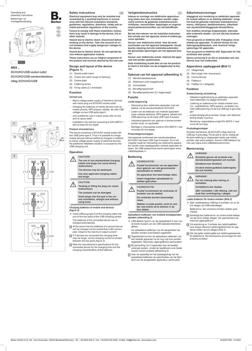
Steckdosen/Zentralstücke mit Dichtungsset
montieren (Bild 1)
Dichtungsansch (2) in die Up-Dose (1) führen.
Dabei die Ausrichtung (Markierung OBEN/TOP)
beachten.
Gegebenenfalls IP44-Fahne vom Dichtungs-
ansch abtrennen (Bild 3).
Bei Einbau in waagerechten Kombinationen:
Jeder Dichtungsansch benötigt die angeformte
IP44-Fahne (Bild 2).
Bei Einbau in senkrechten Kombinationen:
Nur der untere Dichtungsansch benötigt die
angeformte IP44-Fahne (Bild 3).
Schaltereinsatz (3) oder Steckdoseneinsatz (4)
anschließen und in der UP-Dose montieren
Wasseraurittsönung der Dichtung freilegen
Bei Einbau in waagerechten Kombinationen:
An den nach unten zeigenden Wasserauritt-
sönungen das Silikon entlang der Markierung
abtrennen und entfernen (Bild 4)
Bei Einbau in senkrechten Kombinationen:
Nur an der unteren Wasseraurittsönung das
Silikon entlang der Markierung abtrennen und
entfernen (Bild 5)
Dichtung (5) auf den Tragring legen.
Rahmen (6) aufsetzen.
Designabdeckung montieren.
Bei Schaltereinsätzen (3):
Rahmen über Verschrauben des Befeigungs-
ücks (8) fixeren und Wippe (9) aufraen.
Bei Steckdosen (4):
Rahmen über Verschrauben des Steckdosen-
Zentralücks (7) fixieren.
Sealing set for socket outlets/
centre plates/switches/push-buttons
Safety instructions
Degree of protection IP44 is only guaranteed if as-
sembly is performed in accordance with these in-
structions.
Electrical equipment may only be installed and
assembled by qualifi ed electricians.
Disconnect before working on the device. Take
into account all circuit breakers that supply dan-
gerous voltages to the device or load.
Failure to comply with these instructions may re-
sult in damage to the device, fi re or other hazards.
Function
Correct use
Degree of protection IP44 can be achieved during
inallation
- in ush-mounted boxes according to DIN 49073,
Part 1
- on smooth, even, vertical walls
- in ush-mounted boxes..
Degree of protection IP 44 is not ensured in the case
of oor mounting, ceiling mounting and mounting in
hollow-wall boxes.
Information for electricians
Installation
DANGER!
Touching live parts can result in an elec-
tric shock!
An electric shock can be lethal!
Disconnect the connecting cables before
working on the device and cover all live
parts in the area!
ç
Install socket outlets/centre plates with the
sealing set (Figure 1)
Insert sealing ange (2) into the ush-mounted
box (1). Note the proper direction (marking
OBEN/TOP).
If necessary, separate IP44 lug from sealing ange
(Figure 3).
For inallation in horizontal combinations:
Each sealing ange requires the integrally mould-
ed IP44 lug (Figure 2).
For inallation in vertical combinations:
Only the lower sealing ange requires the
integrally moulded IP44 lug (Figure 3).
Connect switch insert insert (3) or socket outlet
insert (4) and inall into the ush-mounted box.
Expose the water outlet opening of the sealing
For inallation in horizontal combinations:
Remove and tear o the silicone along the mark-
ing at the downward pointing water outlets
(Figure 4)
For inallation in vertical combinations:
Remove and tear o the silicone along the mark-
ing only at the lower water outlets (Figure 5)
Place sealing (5) on the supporting ring.
Attach frame (6).
Inall design cover.
With switch inserts (3):
Fix frame by screwing the fixing element (8) and
snap rocker (9).
With socket outlets (4):
Fix frame by screwing the socket outlet centre
plate (7).
IP44 IP44IP44
2
e z m
IP44
OBEN TOP
Berker K
24301
IP44
3
4
5
IP44
(2)
(6)
(3)
(5)
(7)
(1)
(4)
(8)
(9)
1
Zestaw uszczelniający do gniazdek/
elementów centralnych/łączniki/łączniki
przyciskowe
Wskazówki dotyczące bezpieczeństwa
Klasa ochrony IP44 zapewniona jest tylko wtedy,
gdy montaż odbywa się zgodnie z niniejszą in-
strukcją!
Zabudowa i montaż urządzeń elektrycznych mogą
być wykonywane wyłącznie przez wykwalifi kowa-
nych elektryków.
Przed wykonywanie prac przy urządzeniu trzeba
je odłączyć od napięcia elektrycznego. Należy
przy tym uwzględnić wszystkie wyłączniki zabez-
pieczające instalacji, które dostarczają do urzą-
dzenia niebezpieczne napięcia.
Nieprzestrzeganie instrukcji może doprowadzić
do uszkodzenia urządzenia, pożaru lub innych
niebezpieczeństw.
Funkcja
Użycie zgodnie z przeznaczeniem
Klasa ochrony IP44 osiągana je przy montażu
- w gniazdach podtynkowych zgodnie z DIN 49073,
cz. 1
-na gładkich, płaskich ścianach pionowych
- w gniazdach podtynkowych montowanych na rów-
ni z tynkiem.
Klasa ochrony IP44 nie je zagwarantowana przy
montażu podłogowym, sufitowym i w gniazdach
w ścianach puych.
Informacje dla elektroinstalatorów
Montaż
NIEBEZPIECZEŃSTWO!
Niebezpieczeństwo porażenia prądem
przy dotknięciu elementów znajdujących
się pod napięciem!
Porażenie prądem może doprowadzić do
śmierci!
Przed rozpoczęciem prac przy
urządzeniu należy odłączyć przewody
przyłączeniowe od sieci, a także osłonić
sąsiednie elementy znajdujące się pod
napięciem!
ç
Montaż gniazdek/elementów centralnych
z zestawem uszczelniającym (rysunek 1)
Wawić kołnierz uszczelniający (2) w gniazdo
podtynkowe (1). Zwrócić przy tym uwagę na ua-
wienie (oznaczenie OBEN/TOP).
Ew. usunąć oznaczenie IP44 z kołnierza uszczel-
niającego (rysunek 3).
W przypadku zabudowy w kombinacjach poziomych:
każdy kołnierz uszczelniający musi być zaopatrzony
w dopasowane oznaczenie IP44 (rysunek 2).
W przypadku zabudowy w kombinacjach pionowych:
Tylko dolny kołnierz uszczelniający musi być
zaopatrzony w dopasowane oznaczenie IP44
(rysunek 3).
Zamontować wkład wyłącznika (3) lub wkład
gniazda (4) w gnieździe podtynkowym.
Odsłonić otwór wypływu wody uszczelki
W przypadku zabudowy w kombinacjach pozio-
mych: Przy skierowanych w dół otworach wypływu
wody oddzielić silikon wzdłuż zaznaczenie i usu-
nąć (rysunek 4)
W przypadku zabudowy w kombinacjach pionowych:
Jedynie przy dolnym otworze wypływu wody
odd-zielić silikon wzdłuż zaznaczenie i usunąć
(rysunek 5)

Berker GmbH & Co. KG - Zum Gunterstal - 66440 Blieskastel/Germany - Tel.: +49 6842 945 0 - Fax: +49 6842 945 4625 - E-Mail: info@berker.de - www.berker.com - 6LE005105B - 11/2020
Dichtungsset für Steckdosen/
Zentralstücke/Schalter/Taster
Schlüsselschalter-/taster mit Dichtungsset
montieren (Bild 6)
Für die Schutzart IP44 darf die Montage nur mit
Dichtungsset 1fach (Be.-Nr. 10108901) und nicht in
Kombinationen erfolgen.
Dichtungsansch (2) in die Up-Dose (1) führen.
Dabei die Ausrichtung (Markierung OBEN/TOP)
beachten.
Einsatz (3) anschließen und in der Up-Dose
montieren.
Dichtung (4) auf den Tragring legen. Dabei die
Ausrichtung (Wasseraurittsönung unten) beach-
ten.
Schließzylinder (8), Zentralück (6) und Erdungs-
fahne (7) zusammensetzen. Hierzu Schließzylin-
der von vorne bis zum Anschlag in das Zentral-
ück führen. Schließzylinder und Erdungsfahne
über die Schraube in dargeellter Weise am
Zentralück befeigen.
Rahmen (5) mit dem Zentralück (6) auf dem
Einsatz positionieren. Hierbei die Erdungsfahne
in die entsprechende Aufnahme des Einsatzes
führen.
Zentralück mit Einsatz verschrauben.
Abdeckung (9) über den Schließzylinder schieben
und im Zentralück einraen.
Gewährleistung
Technische und formale Änderungen am Produkt, so-
weit sie dem technischen Fortschritt dienen, behalten
wir uns vor.
Wir leien Gewähr im Rahmen der gesetzlichen
Beimmungen.
Im Gewährleiungsfall bitte an die Verkaufselle
wenden.
Sealing set for socket outlets/
centre plates/switches/push-buttons
Mount key switch/key push-button with
sealing set (Figure 6)
For the degree of protection IP44 the inallation
may only be done with sealing set 1gang (order no.
10108901) and not in combinations.
Insert sealing ange (2) into the ush-mounted
box (1). Note the proper direction (marking
OBEN/TOP).
Connect insert (3) and inall into the ush-mount-
ed box.
Place sealing (4) on the supporting ring. Note the
proper direction (water opening outlet).
Assemble lock cylinder (8), centre plate (6) and
earthing lead (7). To do this, insert lock cylinder
into the centre plate from the front up to the op.
Attach lock cylinder and earthing lead to the centre
plate over the screw as illurated.
Position frame (5) together with the centre plate
(6) on the insert. Here, insert the earthing lead into
the appropriate mounting device of the insert.
Screw centre plate together with insert.
Push cover (9) over the lock cylinder and snap into
place in the centre plate.
Warranty
We reserve the right to make technical and formal
changes to the product in the intere of technical
progress.
Our products are under guarantee within the scope of
the atutory provisions.
If you have a warranty claim, please contact the
point of sale or ship the device poage free with a
description of the fault to the appropriate regional
representative.
IP44
(3)
(5)
(7)
(1)
(4)
(8)
(9)
(2)
(6)
6
Nałożyć uszczelkę na pierścień nośny (5).
Założyć ramkę (6).
Zamontować pokrywkę ozdobną.
Przy wkładach wyłącznikowych (3):
zamocować ramkę poprzez przykręcenie elementu
mocującego (8) i założyć dźwignię wyłącznikową (9).
Przy gniazdach wtykowych (4):
zamocować ramkę poprzez przykręcenie central-
nego elementu gniazda wtykowego (7).
Zestaw uszczelniający do gniazdek/
elementów centralnych/łączniki/łączniki
przyciskowe
Montaż łącznika na klucz z zestawem
uszczelniającym (rysunek 6)
Klasa ochrony IP44 zoaje zapewniona wyłącznie
wtedy, gdy montaż naępuje z użyciem zeawu
uszczelniającego 1-krotnego (nr zam. 10108901) i nie
w kombinacji.
Wawić kołnierz uszczelniający (2) w gniazdo
podtynkowe (1). Zwrócić przy tym uwagę na ua-
wienie (oznaczenie OBEN/TOP).
Podłączyć mechanizm (3) i zamontować w gnieź-
dzie podtynkowym.
Nałożyć uszczelkę na pierścień nośny (4). Zwrócić
przy tym uwagę na uawienie (otwór wypływu
wody na dole).
Zmontować wkładkę bębenkową (8), płytka czo-
łowa (6) i element uziemiający (7). W tym celu od
przodu wsunąć wkładkę bębenkową do elementu
centralnego aż do oporu. Za pomocą śruby zamo-
cować wkładkę bębenkową i element uziemiający
na elemencie centralnym w sposób przedawiony
na rysunku.
Ramkę (5) wraz z elementem centralnym (6)
umieścić na mechanizmie. Wprowadzić przy tym
element uziemiający do odpowiedniego elementu
mocującego w mechanizmie.
Przykręcić płytka czołowa do mechanizmu.
Przesunąć pokrywę (9) nad wkładkę bębenkową i
zatrzasnąć w elemencie centralnym.
Rekojmia sprzedawcy
Producent zarzega sobie prawo do zmian tech-
nicznych i formalnych, o ile celem ich je techniczne
ulepszenie produktu.
W razie reklamacji urządzenie należy zwrócić do
punktu sprzedaży wraz z opisem charakteru uerki.
This manual suits for next models
1
Other Berker Home Automation manuals
