Berker KNX-Funk User manual

4 6T 7298-30a1
6T 7298-30a
6T 7298-30a
4
3
7
5
1
6
2
Das KNX-Funk/TP Gateway dient als Schnittstelle
zwischen drahtgebundenen und funkgesteuerten
Geräten der Gebäudesystemtechnik KNX.
Legende
1LED Datenverkehr KNX TP (Twisted Pair)
2,3Tasten +/-zur physikalischen Adressierung
4Antenne
5LED Datenverkehr KNX-Funk
6Display 2 x 8 Segmente
7Abdeckklappe
Konf gurat onsarten
• ETS3/ETS4: Applikation, Produktdatenbank und
Dokumentation beim ersteller erhältlich.
• tebis TX: Konfiguration über Verknüpfungsgerät
von ager.
Funkt onen
• Schnittstelle zwischen drahtgebundenen und
funkgesteuerten Produkten, Ansteuerung über
KNX-Bus.
• Anzeigefunktion der Bus- und Funk-Telegramme
mittels LEDs und Display mit 2 x 8 Segmenten.
Die genauen Funktionen des Gerätes hängt von
seiner Konfiguration und den jeweiligen
Parametereinstellungen ab.
Anschluss, Test und Inbetr ebnahme
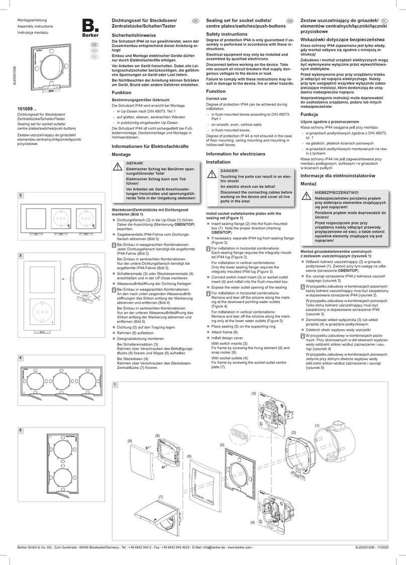
Abdeckklappe 7mit ilfe eines Schraubendrehers
entfernen und das Gerät über Bus-Klemme an den
KNX-Bus anschließen.
E ngang n den Modus phys kal sche Adress erung
versetzen
Kurze gleichzeitige Betätigung der Tasten 2und 3
.
Anzeige "Ad" auf dem Display 6.
teb s TX Konf gurat onsmodus akt v eren
Eine Betätigung (4 s ≤ t < 10 s) der Taste 2oder
3versetzt das Gerät in den tebis TX-
Konfigurationsmodus und bewirkt das Aufleuchten
der LED 5. Anzeige "CF" auf dem Display 6.
Werkse nstellung
Tasten 2und 3gleichzeitig betätigen und
10 s gedrückt halten.
Anzeige "Fa" auf dem Display 6.
Anze ge für schwache Batter eladung des
verbundenen Funk-Gerätes
Anzeige "Lo" auf dem Display 6.
Anze ge ETS/teb s TX-Konf gurat onsmodus
Anzeige “CF” auf dem Display 6
.
OBereits mit quicklink&konfigurierte Geräte
sind vor einer ETS-Konfiguration auf
Werkseinstellung zurückzusetzen.
The KNX-RF/TP gateway provides an interface
between wired devices and radio-controlled
devices within a KNX installation.
Capt on
1KNX TP traffic indication LED
2,3Physical addressing buttons
4Antenna
5KNX-RF traffic indication LED
62 x 8-segment display
7Cover flap
Conf gurat on
• ETS3/ETS4 : application, product database
and documentation available from the
manufacturer.
• tebis TX: configuration using connection
device from ager.
Features
• Interface between wired and radio-controlled
devices, controlled via KNX bus.
• Bus and radio telegram visualization by LEDs
and 2 x 8 segment display.
The individual features of this device depend
on configuration and parameter setting.
W r ng, test and start-up
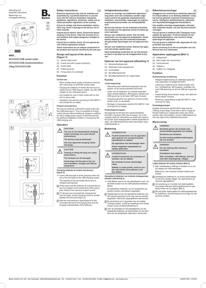
Remove cover 7using a screwdriver,
then connect the device to KNX bus via
bus terminal.
Enter ng phys cal address ng mode
Press No. 2and 3
keys shortly and
simultaneously.
Display No.6shows "Ad".
Act vat ng teb s TX conf gurat on mode
A press (4 s ≤ T < 10 s) on key No. 2or 3
sets product into tebix TX configuration mode
and triggers LED 5switch-on.
Display No. 6shows "CF".
Reset to factory sett ng
Press
simultaneously
keys No. 2and 3
for 10 s.
Display No. 6shows "Fa".
Low battery nd cat on for a connected rad o
product
Display No. 6shows "Lo".
ETS/teb s TX conf gurat on mode nd cat on
Display No. 6shows “CF”
.
ODevices that have already been configured
with quicklink&should be reset to the
factory settings before an ETS
configuration.
Usable in all Europe and in Switzerland
ereby, Berker Gmb & Co. KG, declares that this media
coupler is in compliance with the essential requirements
and other relevant provisions of Directive 1999/5/EC.
The CE declaration can be consulted on the site :
www.hagergroup.net
Verwendbar in ganz Europa und in der Schweiz
iermit erklärt Berker Gmb & Co. KG, dass sich dieser/
diese/dieses Medienkoppler in Übereinstimmung mit den
grundlegenden Anforderungen und den anderen relevan-
ten Vorschriften der Richtlinie 1999/5/EG befindet".
(BMWi)
Die CE-Konformitätserklärung ist auf der Webseite:
www.hagergroup.net zugänglich.
Best.-Nr./Order no./Nr. ord. 8505 01 00
Berker Gmb & Co. KG
Klagebach 38
58579 Schalksmühle/Germany
Telefon: + 49 (0) 23 55/90 5-0
Telefax: + 49 (0) 23 55/90 5-111
www.berker.com
08/2012
97-85050-100
D§¶
Bedienungsanleitung
Operation instructions
Istruzioni per l'uso
Caut on:
-This device must be installed only by
a qualified electrician according to the
installation standards in force in the
country.
-Not suitable for outside installation.
Achtung :
-Einbau und Montage dürfen nur durch eine
Elektrofachkraft gemäß den einschlägigen
Installationsnormen des Landes erfolgen.
- Gerät nicht für die Verwendung im Freien
geeignet.
KNX-Funk/TP Gateway AP
KNX-RF/TP gateway
surface-mounted
KNX-Radio/TP gateway a parete

6T 7298-30a3
OCOM 114760
2 6T 7298-30a
Bus
Versorgungsspannung Supply voltage Tensione di
alimentazione 30 V DC
(SELV, TBTS)
Sendefrequenz Transmission
frequency Frequenza portante 868,6 M z
Abmessungen Dimensions Ingombro 203 x 77 x 26,5 mm
Schutzart Degree of protection Grado di protezione IP 30
Betriebstemperatur Operating temperature Temperatura
di funzionamento 0 … +45 °C
Lagertemperatur Storage temperature Temperatura
di stoccaggio -20 … +70 °C
Receiver category 2
Transmitter duty cycle 1 %
Techn sche Daten / Techn cal character st cs / Caratter st che tecn che
Il KNX-Radio/TP gateway assicura l’interfaccia
tra prodotti muniti di filo e prodotti radio della
sistema KNX.
Legenda :
1LED per visualizzazione dello traffico dati
KNX TP
2,3Pulsanti d’indirizzamento fisico
4Antenna
5LED per visualizzazione dello traffico dati
KNX-Radio
6Display 2 x 8 segmenti
7Coperchio di copertura
Conf guraz one
• ETS3/ETS4: software applicativo, base di
dati e descrizione del software disponibile
presso il costruttore.
• tebis TX: configurazione attraverso il
dispositivo di ager
Funz on
• Interfaccia tra prodotti radio e prodotti muniti
di filo tramite il bus KNX.
• Visualizzazione dei telegrammi bus e radio
mediante LEDs e display 2 x 8 segmenti.
Le precise funzioni di questo prodotto
dipendono dalla configurazione e dai
parametri.
Cablagg o, test e messa n funz one
Rimuovere il coperchio di copertura 7con un
cacciavite, quindi collegare il prodotto al bus
KNX.
Entrata n modo Ind r zzamento f s co
Pressione corta simultanea sui tasti 2e3
.
Visualizzazione "Ad" sul display 6.
Att vare l modo d conf guraz one teb s TX
Una pressione (4 s ≤ t < 10 s) sui pulsante 2
o3provoca l'entrata del prodotto in modalità
di accoppiamento e l’accensione del LED 5.
Visualizzazione "CF" sul display 6.
Reset prodotto
Pressione simultanea di 10 s sui tasti 2e3.
Visualizzazione "Fa" sul display 6.
Ind caz one d batter a bassa per un prodotto
rad o collegato
Visualizzazione "Lo" sul display 6.
Ind caz one modo d conf guraz one
ETS/teb s TX
Visualizzazione “CF” sul display 6.
OPrima di una configurazione ETS ripristi-
nare le impostazioni di fabbrica nei
dispositivi già configurati tramite
quicklink&.
Attenz one :
-L’apparecchio va installato unicamente
da un elettricista qualificato secondo le
norme d’installazione in vigore nel
paese.
-Non idoneo ad installazione in esterni.
Usato in Tutta Europa e in Svizzera
Con la presente Berker Gmb & Co. KG dichiara che
questo accoppiatore di apparecchi è conforme ai requisiti
essenziali ed alle altre disposizioni pertinenti stabilite dalla
direttiva 1999/5/CE.
La dichiarazione CE può essere trovato sul sito web:
www.hagergroup.net
4
3
7
5
1
6
2
DBohrung
§Fixing diagram
¶Piano di foratura
This manual suits for next models
2
Other Berker Home Automation manuals
