Berker 7531 00 01 User manual

Schaltaktor 16fach
Best. Nr. 7531 00 01
D
GB NL F N E
825 433 01 07.2003
Bedienungsanleitung

Dieses Gerät ist ein Produkt des instabus-EIB-Systems und ent-
spricht den EIBA-Richtlinien. Detaillierte Fachkenntnisse durch
instabus-Schulungen werden zum Verständnis vorausgesetzt.
Die Funktion des Gerätes ist softwareabhängig. Detaillierte Infor-
mationen, welche Software geladen werden kann und welcher
Funktionsumfang sich damit ergibt sowie die Software selbst,
sind der Produktdatenbank des Herstellers zu entnehmen.
Planung, Installation und Inbetriebnahme des Gerätes erfolgen
mit Hilfe einer von der EIBA zertifizierten Software.
Gefahrenhinweise
D
Systeminformation
D
Gefahrenhinweise
Achtung! Einbau und Montage elektrischer Geräte dürfen
nur durch eine Elektrofachkraft erfolgen.Dabei sind die gelten-
den Unfallverhütungsvorschriften zu beachten.
ZurVermeidung eines elektrischen Schlages, vor Arbeiten am
Gerät freischalten (Sicherungsautomat abschalten).
Bei Nichtbeachtung der Installationshinweise können Schä-
den am Gerät, Brand oder andere Gefahren entstehen.
Bei Verwendung als Rollladenaktor: Nur für den Anschluss
von Motoren! Gefahren, die durch motorisch angetriebene
Komponenten entstehen können, sind durch geeignete
Sicherheitsmaßnahmen auszuschließen.

Hinweise
D
Funktion
D
Der Aktor kann je nach Parametrierung als Schaltaktor (max.
16fach) oder Rollladenaktor (max. 8fach) eingesetzt werden.
Auch eine Mischung der Funktionen ist möglich, z.B. Ausgänge
A1 – A6 als Schaltaktor 6fach, Ausgänge A7 – A16 als
Rollladenaktor 5fach.
Für die Funktion Rollladenaktor sind für einen Motor jeweils 2
Ausgänge zu kombinieren.
Das Gerät benötigt eine zusätzliche Stromversorgung.
Über die Bedien- und Anzeigeelemente kann der Aktor je nach
Parametrierung auch ohne Busspannung komfortabel per Hand
bedient werden. Dazu zählt auch eine zentrale Ausschalt-
möglichkeit per Hand.
Siehe dazu Kapitel Handbedienung.
Schalterbetrieb:
•Die Relaisausgänge eines Aktors schalten bei Ansteuerung
über ein Zentraltelegramm mit geringer zeitlicher Verzögerung.
•Keine Drehstrommotoren anschließen.
•Eine Belegung von 230 V und SELV an verschiedenen Ausgän-
gen eines Aktors ist nicht zulässig.
Rollladenbetrieb:
•Bei Rollladenbetrieb werden zwei benachbarte Relaisausgänge
zu einem Rollladenausgang zusammengefasst.Der jeweils linke
(1, 3, 5, …) Relaisausgang ist für die Auf-Fahrtrichtung, der
rechte (2, 4, 6, …) für die Ab-Fahrtrichtung bestimmt.

Eigenschaften
D
Hinweise
D
Rollladenbetrieb:
•Sollen Motoren parallel geschaltet werden, unbedingt Angaben
der Motorenhersteller beachten. Andernfalls könnten die Moto-
ren zerstört werden.
•Nur Rollladen mit Endlagenschalter (mechanisch oder elektro-
nisch) verwenden. Die Endschalter der angeschlossenen Moto-
ren sind auf korrekte Justierung zu überprüfen.
•Durch einen Defekt eines Rollladenausgangs kann auch der
angeschlossene Motor Schaden nehmen.
•Durch die Aktivierung der Handbedienung werden alle Zeitab-
läufe sowie die Sicherheitsfahrt bei Sturm beendet. Die
Sicherheitsfahrtbei Sturm wirdbeiVerlassen derHandbedienung
nachgeholt.
•Bei Handbedienung nur Dauerlauf (langer Tastendruck) und
Stopp (kurzer Tastendruck) möglich.
Rollladenbetrieb:
•Umschaltzeit bei Fahrtrichtungswechsel einstellbar (Angaben
des Motorenherstellers beachten!)
•Verriegelung der Laufrichtungen per Software
•Sonnenschutzfunktion
•Sicherheitsfahrt bei Sturm für jeden Rollladenausgang separat
einstellbar
•Verhalten bei Busspannungsausfall und -wiederkehr einstellbar
Für weitere Eigenschaften lesen Sie bitte die zugehörige EIB
Produktdokumentation.

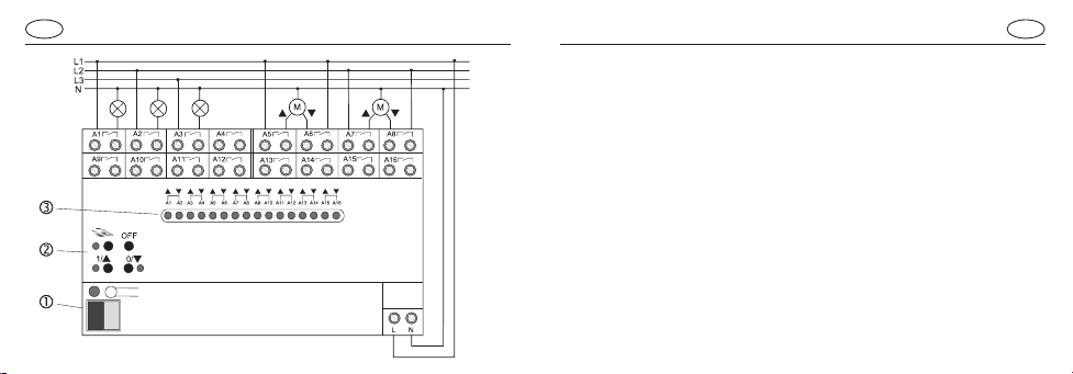
Der Busanschluss erfolgt mit der Busanschlussklemme (1).
Der Anschluss der Versorgungsspannung und der Lasten erfolgt
gemäß Abb. A. Im Bild ist der Anschluss von 3 Lampen an den
Ausgängen A 1 – A3 und 2 Motoren an den Ausgängen A5/A6 und
A7/A8 beispielhaft dargestellt. Der Anschluss weiterer Lasten er-
folgt sinngemäß gleich.
Beachten Sie, dass die angeschlossenen Lasten mit der Para-
metrierung der Ausgänge übereinstimmen müssen.
Es können verschiedene Außenleiter angeschlossen werden.
Weiter bedeuten:
(2): Handbedienelemente und Statusanzeigen
(3): LED A1 – A16 zur Anzeige des Schaltzustands und des bei
Handbedienung ausgewählten Ausgangs.
Anschluss
D
Anschluss
D
A

D
D
Abdeckkappe
Die Abdeckkappe mit nach unten herausgeführten Busleitungen
über die Busklemme schieben (Abb. E) bis sie spürbar einrastet.
Entfernen Sie die Abdeckkappe durch seitliches Drücken
und Abziehen (Abb. F).
Abdeckkappe
EF

D
D
Bedien- und Anzeigeelemente siehe Abb. D
Permanente Umschaltung auf Handbedienung: Drücken Sie ca. 5
Sekunden die Taste bis die zugehörige LED aufleuchtet. Der
Aktorbefindet sich nunpermanent imHand-betrieb,dieAnsteuerung
über den EIB ist gesperrt.
Kurzes Drücken derTaste wählt die Ausgänge aus, die geschal-
tet werden sollen. Blinkt nur eine LED ist der Ausgang als Schalter
parametriert, 2 blinkende LED zeigen Rollladenfunktion an.
Mit den Tasten 1/=und 0/>kann der über die blinkenden LED A1–
A16 angezeigte Ausgang geschaltet werden, die LED neben den
Tasten zeigen den Schaltzustand an. Der Schaltzustand der nicht
ausgewählten Ausgänge wird, wie beim Busbetrieb, über die LED
A1 –A16 angezeigt.
Handbedienung abschalten: Drücken Sie ca. 5 Sekunden die
Taste , bis die zugehörige LED erlischt.
HandbetriebHandbetrieb
D

D
D
HandbetriebHandbetrieb
Zeitweise Umschaltung auf Handbedienung:
Drücken Sie kurz dieTaste , bis die LED A1 oder LED A1 und A2
blinken, der Schaltzustand wird über die LED 1/=und 0/>ange-
zeigt. LED bleibt aus.
Der Aktor befindet sich nun im Handbetrieb, die Ansteuerung über
den EIB ist gesperrt. Erfolgt für länger als 5 Sekunden keine
weitere Tastenbetätigung, verlässt der Aktor den Handbetrieb und
schaltet automatisch auf Busbetrieb zurück.
Mit den Tasten 1/=und 0/>kann der über die LED A1 – A16
angezeigte Ausgang geschaltet werden. Die zugehörigen LED
zeigen den Schaltzustand an.
Kurzes Drücken der Taste wählt die weiteren Ausgänge aus,
deren Status angezeigt oder geschaltet werden sollen.
Sind alle Ausgänge A1 – A16 einmal ausgewählt worden, schaltet
der Aktor automatisch den Handbetrieb ab.
Zentrale Abschaltfunktion:
Der Aktor verfügt über eine zentrale Abschaltfunktion, wenn er sich
in der permanenten Handbedienung befindet.
Um die zentrale Abschaltung zu aktivieren drücken Sie kurz die
Taste OFF.Alle Relais (Schalt- und Rollladenfunktionalität) werden
ausgeschaltet.
Hinweis: Die zentrale Abschaltung ist nicht bei zeitweiser Umschal-
tung auf Handbedienung verfügbar.

Technische DatenTechnische Daten
Versorgung instabus EIB : 21 - 32 V DC
LeistungsaufnahmeinstabusEIB : max.150 mW
Versorgung Netz : AC 110V (-10%)…240V (+10%)
50/60 Hz
Gesamtverlustleistung : max.5,5W
Anschluss instabus EIB : instabusAnschlussklemme
Anschluss Netz : Schraubklemmen
1,5 – 4 mm² eindrähtig oder
2 x 1,5 – 2,5 mm² eindrähtig
0,75 – 4 mm² feindrähtig
ohne Aderendhülse oder
0,5 – 2,5 mm² feindrähtig
mitAderendhülse
D
D
Umgebungstemperatur : -5 °C bis +45 °C
Lagertemperatur : -25 °C bis +70 °C
Einbaubreite : 144 mm (8 TE)
Ausgänge
Kontaktart :potenzialfreie Schließer (µ-Kontakt)
Schaltspannung : AC 250 V
Schaltvermögen AC 250V : 10 A
Schaltleistung
Glühlampen : 1400W
HV-Halogenlampen: : 1225W
NV-Halogenlampen: : 1200VA
TronicTrafos : 1200 VA
Motoren : 600 W
Leuchtstofflampen :keine Freigabe
TechnischeÄnderungenvorbehalten
D
OperatingInstructions
Switching actuator, 16-channel
Best. Nr. 7531 00 01
D
GB
NL F N E
Gewährleistung
Wir leisten Gewähr im Rahmen der gesetzlichen Bestimmungen.
Bitte schicken Sie das Gerät portofrei mit einer Fehlerbeschreibung
an unsere zentrale Kundendienststelle:
Berker GmbH & Co. KG
Abt.Service Center
Klagebach 38
D-58579Schalksmühle
Telefon: 0 23 55 / 90 5-0
Telefax: 0 23 55 / 90 5-111

Safety warnings
Attention:Electrical equipment must be installed and fitted only
by qualified electricians and in observance of the applicable
accident prevention regulations.
To prevent electric shocks,disconnect the power supply before
working on the device (by cutting out the circuit breaker).
Any non-observance of the fitting instructions may cause fire or
other hazards.
Shutter actuator applications: Connect only shutter motors to
the device.
Appropriate safety measures must be taken to exclude any
hazards deriving from motor-operated components.
Safety warningsSystem information
GBGB
This unit is a product of the instabus-EIB-System and corresponds
to the EIBA Guidelines. Detailed technical knowledge acquired in
instabus training courses is a prerequisite for the understanding of
the system. The functions of the device are software-dependent.
Detailed information on the software and the functions implemented
and the software itself are available from the manufacturer’s product
data bank.
Planning, installation and commissionning of the device are effected
with the help of EIBA-certified software.
Depending on parameterization, the actuator can either be used as
switching actuator (max. 16 channels) or as shutter actuator (max.
8 channels). Functions can also be mixed, e.g. outputs A1 – A6 as
switching actuator with 6 channels, outputs A7 – A16 as shutter
actuator with 5 channels.
In the shutter actuator mode, two outputs must be combined for
each motor.
The device needs an additional power supply.
By means of the control and display elements, the actuator - if
parameterized accordingly - can also be readily operated by hand
without bus voltage. This includes also the possibility of central
shutoff by hand.
Cf. also the chapter on manual operation.
Switching operation:
•The relay outputs of an actuator switch with a slight time delay
when controlled by a central telegram.
•Do not connect tri-phase AC motors.
•The connection of 230 V and SELV voltages to different outputs
of an actuator is not permitted.
Shutter operation:
•For shutter operation, 2 neighbouring relay outputs are used as
one shutter output.The left (1, 3, 5, …) relay outputs are reserved
for the UP movements and the right ones (2, 4, 6, …) for the the
DOWN movements.
ImportantFunction
GBGB
GBGB
Shutter operation:
•Ifmotors areto be connectedin parallel,itis absolutelynecessary
to observe the instructions of the motor manufacturers. The
motors can otherwise be irreparably damaged.
•Use only shutters with limit switches (mechanical or electronic).
The limit switches of the motors connected must be checked for
proper adjustment.
•A defect of a shutter output may also result in damage to the
motor.
•Activation of the manual operation mode terminates all time
delays and the safety shutdown function in stormy weather. The
safety shutdown during stroms is reactivated when the manual
operation mode is ended.
•The manual mode permits only continuous movements (long
press) and stop (short press).
Shutter operation:
•Switch-over time duringchange ofmovementdirection adjustable
(observe the instructions of the motor manufacturer)
•movement directions lockable by software control
•Sun protection function
•Safety shutdown during storms separately adjustable for each
shutter output
•Response on bus voltage failure and return adjustable
For further characteristics, please read the corresponding EIB
product documentation.
CharacteristicsImportant
Connection
GB
The bus line is connected to the bus connecting terminal (1).
The supply voltage and the loads are connected as per fig. A.The
illustration shows the connection of 3 lamps to outputs A 1 – A3 and
of 2 motors to outputs A5/A6 and A7/A8 as an example. Further
loads are connected in the same way.
Please observe that the connected loads must be compatible with
the parameterization of the outputs.
The device can be connected to different phase conductors.
Further elements:
(2): manual controls and status indicators
(3): LED A1 – A16 indicate the switching state and the output
selected during manual operation.
Connection
GB
A

GBGB
Cap
Slide the cap over the bus terminal with the bus line at the bottom
(fig. B) until it is heard to engage.
Remove the cap by pressing against the sides and by pulling it out
at the same time (fig. C).
Cap
BC

GBGB
Controls and indicators see fig. D
Permanent change to manual operation: depress the for about 5
seconds until the respective LED lights up. The actuator is now
permanently in the manual operation mode. Control via the EIB is
disabled.
A short press on the key selects the outputs to be switched. If
only one LED flashes, the output is parametrized for switching.
2 flashing LEDs indicate the shutter function.
Keys 1/=and 0/>can be used for switching the output indicated by
a flashing LED A1 – A16, the switching state itself being indicated
by the LED beside the keys.The switching state of the non selected
outputs is indicated, as for bus operation, by LEDs A1 –A16.
To quit the manual mode: depress the key for about 5 seconds
until the respective LED goes out.
Manual operationManual operation
D

Manual operationManual operation
GBGB
Central shut-off function:
In the permanent manual operation, the actuator has a central
shut-off function.
To activate the central shut-off function, depress the OFF key
briefly. All relays (switching and shutter functions) are deactivated.
Important: Central shutoff is not available for temporary manual
operation.
Temporary change to manual operation:
Depress the key briefly until LED A1 or LED A1 and A2 are
flashing.The switching state is indicated by LED 1/=and 0/>.
LED remains off.
The actuator is now in the manual mode and the control via the EIB
is disabled. If no key is depressed for more than 5 seconds, the
actuator quits the manual mode and goes automatically back to
bus operation.
Keys 1/=and 0/>can be used for switching the output indicated by
LEDs A1 – A16. The switching state itself is indicated by the LED
beside the keys.
A short press of the key selects the other outputs which are to
be switched or whose status is to be indicated.
When all outputs A1 – A16 have been selected once, the actuator
automatically quits the manual mode.

Technical DataTechnical Data
instabus EIB supply : 21 - 32 V DC
instabusEIB power consumption : max. 150 mW
Mains supply : AC 110V (-10%)…240V (+10%)
50/60 Hz
Total power loss : max.5,5 W
instabusEIB connection : instabusterminal
Mainsconnection : screw-typeterminals
1.5 – 4 mm² single-wire or
2 x 1.5 – 2.5 mm² stranded wire
0.75 – 4 mm² stranded wire
without ferrule or
0.5 – 2.5 mm² stranded wire
with ferrule
GBGB
Ambienttemperature : -5 °C … +45 °C
Storagetemperature : -25 °C +70 °C
Installationwidth : 144 mm (8 pitch units)
Outputs
Type of contact : potential-free n.o.contact (µ contact)
Switched voltage : AC 250 V
Switched current AC 250V : 10 A
Switching capacity
incandescentlamps : 1400W
HVhalogen lamps: : 1225W
LVhalogen lamps: : 1200VA
Tronictransformers : 1200VA
motors : 600 W
fluorescentlamps : notapproved
Technical specifications subject to change

GB
Acceptance of guarantee
Our products are under guarantee within the scope of the statutory
provisions.
Please return the unit postage paid to our central service
department giving a brief description of the fault:
Berker GmbH & Co. KG
Klagebach 38
D-58579Schalksmühle
Germany
Telephone:+49 (0) 23 55 / 90 5-0
Telefax: +49 (0) 23 55 / 90 5-111
Installatie-instructies
Schakelactor 16-voudig
Best. Nr. 7531 00 01
DGB
NL
F N E

Dit apparaat is een product van het instabus-EIB-systeem en
voldoet aan de EIBA-richtlijnen.
Gedetailleerde vakkennis via instabus-trainingen is voor een goed
begrip een eerste vereiste.
Dewerking vanhet apparaat isvandegebruikte softwareafhankelijk.
Gedetailleerde informatie, welke software kan worden geladen en
welke functies hiermee mogelijk zijn, alsmede informatie over de
software zelf, vindt u in de productdatabase van de fabrikant.
Planning, installatie en inbedrijfstelling van het apparaat geschie-
den met behulp van door de EIBA gecertificeerde software.
Attentie!
Installatie en montage van elektrische apparaten mogen
uitsluitend door een landelijk erkend installatiebedrijf worden
uitgevoerd. Daarbij de geldende ongevallen-preventie-voor-
schriften naleven.
Ter vermijding van elektrische schok het toestel voorafgaand
aan de werkzaamheden altijd eerst spanningvrij schakelen
(veiligheidsautomaat uitschakelen).
Bij veronachtzaming van de installatie-instructies kunnen brand
of andere gevaren optreden.
Bij gebruik als rolluik-actor: Uitsluitend geschikt voor aan-
sluiting van motoren! Gevaren die door motorisch aangedreven
componenten kunnen optreden, dienen door geschikte veilig-
heidsmaatregelen te worden uitgebannen.
VeiligheidsinstructiesSysteminformatie
NLNL
Table of contents
Languages:
Other Berker Switch manuals


